www.nature.com/scientificreports
Near-absolute polarization
insensitivity in graphene based
ultra-narrowband perfect visible
light absorber
Deniz Umut Yildirim
1,2, Amir Ghobadi
1,2& Ekmel Ozbay
1,2,3,4Strong light-graphene interaction is essential for the integration of graphene to nanophotonic and optoelectronic devices. The plasmonic response of graphene in terahertz and mid-infrared regions enhances this interaction, and other resonance mechanisms can be adopted in near-infrared and visible ranges to achieve perfect light absorption. However, obtaining near-absolute polarization insensitivity with ultra-narrow absorption bandwidth in the visible and near-infrared regimes remains a challenge. In this regard, we numerically propose a graphene perfect absorber, utilizing the excitation of guided-modes of a dielectric slab waveguide by a novel sub-wavelength dielectric grating structure. When the guided-mode resonance is critically coupled to the graphene, we obtain perfect absorption with an ultra-narrow bandwidth (full-width at half-maximum) of 0.8 nm. The proposed design not only preserves the spectral position of the resonance, but also maintains >98% absorption at all polarization angles. The spectral position of the resonance can be tuned as much as 400 nm in visible and near-infrared regimes by tailoring geometrical parameters. The proposed device has great potential in efficient, tunable, ultra-sensitive, compact and easy-to-fabricate advanced photodetectors and color filters.
Ever since the experimental isolation of graphene in 20041, this monolayer of carbon atoms in a honeycomb
lattice has attracted enormous attention because of its unique electronic, optical, and mechanical properties2–4,
and paved the way for the advent of other two-dimensional materials5,6. The ultra-wideband spectral response
and the huge carrier mobilities make graphene a strong candidate as a backbone of novel nanophotonic and optoelectronic devices. Indeed, graphene-based solar cells7,8, saturable absorbers for the mode-locked ultra-fast
lasers9–11, photodetectors12,13, transparent electrodes14–16, optical modulators17,18 and third harmonic
genera-tion19,20 are demonstrated. Further incorporation of graphene into high-performance optical devices makes
strong light-graphene interaction compulsory. Localized surface plasmons and surface plasmon polaritons sup-ported by graphene in the terahertz (THz) and mid-infrared (MIR) regimes can enhance this interaction and perfect absorption can be achieved21–25. In contrast, in the visible and near-infrared range (Vis-NIR), graphene’s
optical response is dominated by interband transitions, giving a real conductivity with no plasmonic response and graphene effectively mimics a dielectric with considerable loss26. Unpatterned and suspended graphene absorbs
A = πα = 2.3% of the normally incident light without spectral selectivity, defined by the fine structure con-stant α = e2/ℏc. A = 2.3% is actually a significant value for a one-atom thick material. Nevertheless, the absolute
strength of the absorption is low and it limits graphene’s further application in optoelectronics and photovoltaics in the visible spectrum, an example related to our work being low responsivity in photodetectors27,28.
Since graphene plasmons cannot be excited outside the THz and MIR ranges, graphene has to be coupled to other resonant mechanisms to improve the light absorption in the Vis-NIR ranges. Enormous research efforts have been devoted to enhancing the local optical field around graphene and increase light-graphene interaction in the Vis-NIR ranges. The methods to achieve these can be classified into four categories. First, graphene can be placed inside a Fabry-Pérot (FP) cavity29,30. This method can confine large optical fields and significantly enhance 1NANOTAM-Nanotechnology Research Center, Bilkent University, 06800, Ankara, Turkey. 2Department of Electrical and Electronics Engineering, Bilkent University, 06800, Ankara, Turkey. 3Department of Physics, Bilkent University, 06800, Ankara, Turkey. 4UNAM-Institute of Materials Science and Nanotechnology, Bilkent University, Ankara, Turkey. Correspondence and requests for materials should be addressed to D.U.Y. (email: [email protected]) or E.O. (email: [email protected])
Received: 24 July 2018 Accepted: 1 October 2018 Published online: 12 October 2018
OPEN
the absorption in graphene. However, these designs require deposition of a large number of dielectric layers (25 pairs of AlAs and AlGaAs for the bottom reflector and 7 pairs of SiO2 and Si3N4 layers for top reflectors, reported
in ref.29) on top of graphene. This results in not only fabrication difficulty, but also bulky devices. Another option
is placing graphene near plasmonic nanostructures31–34 and relying on the near-field enhancement effect of
sur-face plasmons or sursur-face plasmon polaritons. This method suffers from absorption peak broadening because of the background absorption coming from the metals, which is detrimental to color sensitivity. Moreover, signifi-cant Joule losses decrease device efficiencies35.
The third and fourth methods can be classified together as coupling of graphene to guided-mode resonances (GMRs) that define the phase-matched coupling between the free-space radiation and the supported (guided) modes with a leaky nature due to their complex wavenumber36–42. The difference between two methods is the
structures where GMRs are excited. The third method is to couple graphene to the GMRs of photonic crys-tal slabs (PhCs)43 or 1-dimensional photonic crystals (1DPCs), excited by sub-wavelength grating (SWG)
cou-plers44,45. The guided-mode leaks out evanescent waves to graphene. Critical coupling of the guided-modes to
graphene then produces perfect absorption. Notably, the latter can achieve an ultra-narrow absorption bandwidth of 0.03 nm due to placing graphene far away from 1DPC45. Although promising in theory, this method enforces
extreme fabrication accuracy on not only the SWG, but also on the 1DPCs to achieve the target wavelength and store very high energy in 1DPC to achieve critical coupling. Similar to the methods that adopt FP cavity, this method also results in bulky components. The final method is to excite the GMRs of either unmodulated slab-waveguide structures beneath the grating46–50, or the grating itself 51, which acts as a waveguide whose core is
refractive-index modulated bulk37,38. These GMRs then interact with graphene to increase light-graphene
inter-action. Compared to the third method, this method offers more compact designs and a more facile fabrication process. This is because it does not require 1DPC, but only a SWG, two or three dielectric films with only one being patterned, and possibly a perfect back metal mirror or Bragg reflector. However, the downside is the larger bandwidth because low-Q resonances can be coupled to graphene, due to the smaller distance between GMR and graphene. Thus, there is a fundamental trade-off between the two methods in terms of the fabrication complexity and Q-factor of resonances. While the previous studies for the guided-mode resonances focused mainly on the absorption enhancement, polarization insensitivity remained an issue, because of incorporating 1-dimensional SWGs. Although polarization-insensitivity between s and p-polarizations is achieved by the square lattice in ref.43,
the bandwidth, measured as full-width at half-maximum (FWHM), 14 nm is quite high because of the circular shape of the holes. The sharp features of gratings allow for enhanced field localizations and high-Q resonances. Hence, an ideal unit-cell would use a rectangular grating structure with rotational symmetry to preserve both strong light absorption and achieve polarization insensitivity.
In the present paper, we employ the finite-difference-time-domain (FDTD) method to numerically propose a novel design that uses a 2-dimensional sub-wavelength grating structure to excite the GMRs of an unmodulated slab waveguide. The critical coupling of the GMRs to graphene yields 99.2% light absorption with 0.8 nm FWHM at 678 nm, under p-polarized (TM) light. The proposed device preserves perfect absorption >98% at all source polarizations as well as the spectral position of the resonance. To the best of our knowledge, this is the first study that illustrates an FWHM below 1 nm with near-absolute polarization independence. Furthermore, the presence of a waveguide structure, instead of 1DPCs or FP cavities, relaxes the device fabrication. The spectral position of the resonance is easily tunable by changing the key geometrical parameters of the device. We first show the enhancement of graphene absorption in a simple optimized grating-core-substrate structure and scrutinize the effect of geometrical parameters on the device characteristics. In the second part, we add a metal back mir-ror and optimize the geometry accordingly to achieve critical coupling, and hence perfect absorption with the ultra-narrow bandwidth. We discuss the design considerations to maximize absorption strength and minimize absorption bandwidth, for each case.
Results and Discussion
Exciting guided-mode resonances of a slab-waveguide to improve light-graphene interaction.
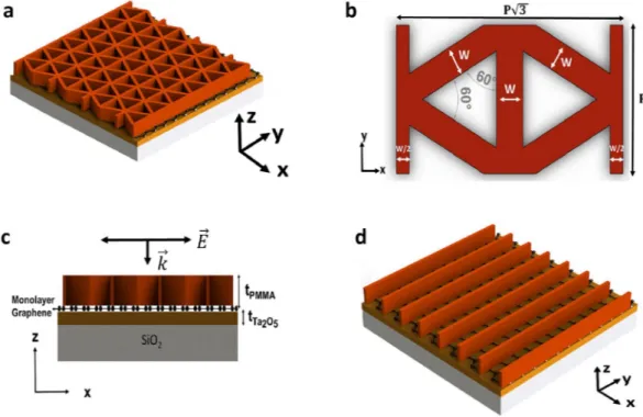
Our proposed device in Fig. 1a is designed to excite the guided-modes in the high-refractive index Tantalum pentoxide (Ta2O5), unmodulated core dielectric region by a unique 2-dimensional sub-wavelengthpolyme-thyl-methacrylate (PMMA) dielectric grating. The structure is supported by glass (SiO2) substrate. We call this
two-port structure Device I. Figure 1b shows the top-view of Device I to indicate the details of our novel 2D sub-wavelength grating, which is based on our previous effort on achieving polarization-insensitivity in wide-band plasmonic absorbers52. Another equivalent unit-cell for the structure is presented in Fig. S1. The dielectric
layers and monolayer graphene of Device I are shown in Fig. 1c. The critical design parameters in determining the spectral position of GMRs and the absorption strength are the thickness of the core region, tTa O2 5; the periodicity,
P, of the unit cell in y-direction, the grating width w, and the grating thickness tPMMA.
To investigate the spectral response of Device I, we utilize finite-difference-time-domain simulations. In the numerical simulations, we illuminated the unit-cell with a broadband plane-wave at normal incidence whose electric-field is polarized in x-direction (φ = 0, p-polarization). In the x and y directions, we use periodic boundary conditions, while in the z-direction perfectly matched layers (PML) are adopted and they are placed 5 wavelengths away from the structure. We use two monitors that are at an adequate distance away from the structure to find the reflected (R) and transmitted (T) power. Absorption is then found by using A = 1 − R − T formula. The dispersion effect of the dielectric materials are retrieved by ellipsometric measurements, and they are in good agreement with the models based on Sellmeier equation53. In the material fits, the only non-zero extinction coefficient comes from
Ta2O5, and is equal to 10−5. It is then reasonable to regard the device as lossless without graphene. Graphene is
mod-eled as a 2-dimensional material with infinitesimal thickness and a complex surface conductivity that includes the chemical potential, scattering rate and temperature effects, based on Kubo formulation54. The surface conductivity is
www.nature.com/scientificreports/
∫
σ μ σ μ σ μ σ μ π ε ε ε ε ε ε Γ = Γ + Γ Γ = − Γ ∂ ∂ − ∂ − ∂ ∞ w T w T w T w T je w j f f d ( , , , ) ( , , , ) ( , , , ) ( , , , ) ( 2 ) ( ) ( ) (1) g c gintra c ginter c gintra c d d 2 2 0 ∫
σ μ π ε ε ε ε Γ = − − Γ − − − Γ − ∞ w T je w j f f w j d ( , , , ) ( 2 ) ( ) ( ) ( 2 ) 4( / ) (2) ginter c d d 2 2 0 2 2where j is the imaginary unit, e is the elemental charge, w is the angular frequency, T is the temperature, ℏ = h/2π is the reduced Planck’s constant, Γ is the scattering rate, and μc is the chemical potential. ε = ε μ− +
− fd( ) (e( c)/k Tb 1) 1 is the Fermi-Dirac distribution and kb is Boltzmann’s constant.
First of all, we set the design parameters tTa O2 5, P, w, and tPMMA to their optimum values of 90 nm, 500 nm,
100 nm (0.2P) and 220 nm, respectively. We simulated Device I without graphene to gain insight about the reso-nance excitation and to confirm that the device is almost lossless. The simulation result in Fig. 2a shows a sharp guided-mode resonance peak at 703.565 nm, and only 1% absorption due to Ta2O5. It is then safe to associate the
absorption in subsequent simulations to graphene. In Fig. 2a, when the device is off-resonant, no diffracted order is coupled to the waveguide, so the device essentially acts as a multilayer film that mostly transmits the incoming wave, and some part is reflected due to Fresnel reflection. When on-resonant, however, one of the diffracted orders couple to the guided-wave in slab waveguide core. The initially diffracted waves of incident wave and the re-diffracted waves of the guided-wave then interfere destructively to produce a transmission filtering response. Essentially, the condition for the particular diffracted order to be guided and the other diffracted orders interfer-ing destructively lead to the same condition36. Another condition for the occurrence of the resonance is the
phase-matching condition, i.e. the real part of the complex wavevector component in the travelling direction of the guided-mode is equal to the components coming from the reciprocal lattice vector of grating and the incident wave21,36,47,48. Eq. 3 provides the phase-matching condition for the devices with 1D grating, as in Fig. 1d under
normally incident light. We call the device in Fig. 1d Device 0.
β π λ = = Λ = Λ k n m n m 2 (3) eff eff 0 0
Figure 1. The proposed design, its unit-cell and the structure with the classical 1D grating. (a) Device I to excite
GMRs and enhance light-graphene interaction. (b) Unit-cell of Device I, detailing the 2D grating, seen from top-view. (c) Dielectric layers and the monolayer graphene of Device I, seen from side-view. (d) The structure with the commonly used 1D-grating. In (c), the device is illuminated by p-polarized plane wave.
where β is the propagation wavenumber along the guiding direction, k0 is the free-space wavenumber, neff is the
effective refractive index of the mode inside the core, m is the diffraction order, λ0 is the free-space wavelength
and Λ is the grating period. Writing an analytical expression for the phase-matching condition in Device I is cum-bersome because our grating diffracts incoming waves in not only the x-direction but also in the y-direction, as opposed to the explicitly used devices with 1D grating44–51 does. Therefore, the guided-mode’s propagation
direc-tion is not simply the x-direcdirec-tion as in Device 0. This makes numerical methods necessary to fully discern the resonances. Another interesting feature of GMRs is their Fano lineshape. It arises due to the interaction between a sharp resonance channel and the broad radiation continuum55. Critically, the zeroth order diffracted wave is a
propagating wave, while all other diffracted orders are evanescent due to the sub-wavelength nature of the grating. Therefore, we have evanescent coupling of the incident wave to the guided-mode.
We then sandwiched monolayer graphene between the grating and Ta2O5 to increase the light-graphene
inter-action, thanks to the guided-wave confined in the waveguide28. The spectral response of the configuration is
shown in Fig. 2b,c for the s (plane of incidence is XZ plane, E-field polarized in y-direction) and p (plane of incidence is XZ plane, E-field polarized in x-direction) polarized incident waves, respectively. From these figures, it is obvious that the structure gives almost identical results in terms of both the absorption strength and the res-onance’s spectral position (65.22% at 703.82 nm for p, 65.17% at 705.05 nm for s). The FWHM of the resonance is also maintained at 3.5 nm. To demonstrate the polarization insensitivity of Device I compared to Device 0, we examined the spectral response of the latter with the structural parameters of the former under s and p-polarized lights. Figure 2d shows the absorption spectrum for Device 0. Although Device 0 can be optimized to maximize absorption strength, the key point in Fig. 2d is that both the spectral position and the strength of absorption are affected from incident light’s polarization. Ref.47 also found that simple 1D grating and unmodulated slab
waveguide structure has a theoretical maximum absorption of 60% without the addition on back-mirror. We, therefore, attribute both the near-stable spectral position of resonance and slightly enhanced absorption to our novel grating design.
Figure 2b,c demonstrate that absorption at the resonance arises mostly due to the detriment of reflection, while a considerable amount of transmission still remains, in harmony with the results reported in ref.47. While
Fig. 2a for Device I without graphene shows almost the complete suppression of transmission, in Device I with
Figure 2. Excitation of GMRs and enhancement of light-graphene interaction. Transmission, Reflectance and
Absorption spectra for the proposed device (a) without graphene, (b) with graphene, under s-polarized (TE) light; (c) with graphene, under p-polarized (TM) light; (d) with 1D grating and graphene, under TE and TM polarized light to show polarization dependency.
www.nature.com/scientificreports/
graphene it can never be zero because of two reasons. First, the guided-wave itself is leaky and leaks out evanes-cent waves to not only graphene (which is the reason of absorption enhancement) but also to the substrate. More importantly, the re-diffracted waves of the guided-mode cannot fully cancel out the initially diffracted waves because of their decreasing amplitude due to graphene.
To get further comprehension about the improvement in the light-graphene interaction, we extracted the elec-tric and magnetic field profiles for both off-resonant and on-resonant cases. A comparison of the fields in the off and on-resonant cases, shown in Fig. 3, clearly indicates a strong field enhancement and localization on graphene. While |E|2 is enhanced two orders of magnitude with respect to the incident light, |H|2 is enhanced one order of
magnitude. The enhanced optical field on graphene is directly responsible for the absorption enhancement, in accordance with Eq. 456,57,
∫ ∫
λ ε λ = ∈ ″ ′| | A w n n E dxdy I ( ) ( ) (4) x y layer, 0 2where ε0 is the vacuum permittivity, λ and I(λ) are the wavelength and the intensity of the light, respectively, n″
and n′ denote the imaginary part (extinction coefficient) and real part of the complex refractive index, respec-tively. The enhancement of fields is slightly higher than the designs incorporating slab waveguide as the guiding layer46–50. We also observe that the standing wave pattern is created in both the z and x-directions. While the
for-mer is because of the waveguiding effect, the latter is due to the refractive index modulation in the x-direction45.
The electric field profile in Fig. 3a implies that the first order mode of the slab waveguide is excited. This is entirely expected because of the deep sub-wavelength thickness of the core region, as the excitation of higher order modes of a waveguide requires larger core thickness58,59.
Reasoning of our 2D SWG to achieve polarization insensitivity. Because it is the most important aspect of our design, we devoted this subsection to the further dissection of polarization insensitivity in Device I, by analyzing what causes the devices with 1D grating, such as Device 0, to be polarization sensitive in the first place. Firstly, different boundary conditions imposed on different polarization states, which results in form birefringence60. Figure 3. Distribution of electric and magnetic field in the on and off-resonant conditions. |E|2/|E0|2 at XZ
plane during (a) on-resonance at 703.82 nm; (b) off-resonance at 751.9 nm; |H|2 at XZ plane during (c)
on-resonance, (d) off-resonance. |E|2 and |H|2 are the modulus of electric and magnetic field inside the device, |E0|2
In addition, when the guided-mode travels along the periodically segmented waveguide61, the periodicity of the
grating defines Bloch modes. Different effective refractive indices of the Bloch modes in the grating region42
con-sequently define different effective mode refractive indices for TE and TM modes of the waveguide. The excitation condition of TE and TM modes are different on top of this58,59,62. Thus, the devices utilizing 1D gratings show
polarization dependency42 as they excite the GMRs at different wavelengths. Moreover, dissimilar field
distribu-tions result in different absorption strengths.
Without considering the waveguiding effects and the complicated properties of Bloch modes, we adopted Rytov’s formulas given in Eqns 5 and 6 for s and p-polarized waves as our guideline in achieving polarization independence. Rytov’s formulas use different boundary conditions forced on different polarization states to find the effective permittivity of the medium to the zeroth order, for deep-subwavelength 1D gratings with sufficient thickness63. = + − n2 fn (1 f n) (5) 12 22 = + − ⊥ n fn f n 1 1 (1 ) 1 (6) 2 12 22
where f is the fill-factor of grating, n1 and n2 are the refractive indices of the grating material, and its surrounding,
respectively. n and n⊥ are the refractive indices of the effective medium for the s-polarized (E-field parallel to
grating grooves), and p-polarized waves (E-field perpendicular to grating grooves), respectively. Any arbitrary incident polarization can then be decomposed into a superposition of s and p-polarizations to find the effective refractive index as a weighted sum of n and n⊥.
From Eqns 5 and 6, we see that it is the different interaction of different polarizations with the 1D grating that is causing polarization sensitivity. Thus, in an absolutely polarization insensitive design, the interaction of E-field with the unit-cell must be the same for all polarization angles. Equivalently, E-field with a fixed polarization angle has to “see” the same unit-cell upon rotating it arbitrarily52. To compare Device I with the devices using 1D
grat-ing, we kept the polarization angle at φ = 0 degrees, and rotated the unit-cells of each for 0, 30, 60, and 90 degrees. The result of this comparison is shown in Fig. 4a. From Fig. 4a, two main conclusions can be made. The first one is that although our grating cannot provide infinite rotational symmetry, its unit-cell repeats itself at every 60°, i.e. we have 60° of rotational symmetry. On the other hand, the 1D grating has different unit-cells, and hence different E-field-unit cell interactions for all polarization angles. Even though the proposed unit-cell for the 0° (60°) and 30° (90°) are different, the interaction of E-field with the unit-cells are somewhat identical. This is because, in the first case, E-field interacts perpendicularly with two gratings [one in the center, one in the corners (2 × 1/2)] and it is at 30 degrees of angle with the other four tilted ones. In the second case, however, E-field is parallel to the former two gratings, but it is at 60 degrees of angle with the tilted ones to compensate for the change in the former. In Fig. S2, we further demonstrate how different polarizations of light interact with the unit-cell. We explored the polarization independence of Device I in more detail by sweeping the polarization angle of the source from 0° to 90°. Our finding in Fig. 4b clearly shows that the structure maintains almost constant absorption at a nearly fixed spectral position.
Technological tolerances, effect of geometrical parameters on GMRs.
Results of the previous subsection demonstrate that GMRs can be excited when the phase-matching condition is satisfied, and the eva-nescent wave from the diffraction grating can be coupled to one of the guided waveguide modes. Although the waveguiding effects on the Bloch modes of the periodically patterned waveguide are complicated, we can still sufficiently understand how the spectral response of Device I depends on the structural parameters, by con-sidering the optical field around graphene. Optical fields at the Ta2O5-PMMA (core-PMMA) and Ta2O5-SiO2(core-substrate) boundaries are highly related to the effective mode index, neff, of the guided-mode if we regard
the structure as an asymmetric dielectric slab waveguide. This is done by considering the SWG as a medium with an effective dielectric permittivity58. Therefore, we start our discussion here by briefly reviewing the fundamental
results of asymmetric dielectric slab waveguide theory58,59,64.
Eqs 7 and 8 are the guided-mode conditions in an asymmetric dielectric slab waveguide for TE and TM modes, respectively, = + −
(
)
(
ht)
p q h tan 1 (7) Ta O pq h 2 5 2 = + −(
)
ht p q h tan( ) 1 (8) Ta O p q h 2 5 2where =h k n0 Ta O22 5−neff2 is the transverse component of wavevector in the core, =p k n0 eff −nSWG
2 2
= −
q k n0 eff2 nSiO2 2 and are the decay constants in PMMA, SiO2 regions, respectively. nSWG is the effective
refrac-tive index of the SWG, different for TE and TM modes. p and q are defined as ∗p nTa O22 5/nSWG2 , ∗q nTa O/nSiO
2 2
2 5 2,
respectively.
It is clear from Eqns 7 and 8 that neff is determined primarily by the thickness of the core to the wavelength
www.nature.com/scientificreports/
show the solution of the transcendental mode-equations for our case, with varying fill-factor for the SWG. Significantly, the modes with higher neff are more tightly confined in the core, so they have low and almost equal
leakage to both PMMA/graphene and substrate. However, for Device I, it is shown in Fig. 2b,c that most of the absorption is due to harnessing the reflection, and it is the transmission losses that prevent the absorption from reaching 100%. Since the transmission can never be made zero in a two-port system, the optimum design must have the maximum optical field at the core-PMMA boundary, while keeping that at the core-substrate boundary minimum. This would ensure that most of the leaked power of the guided-mode is exploited as absorption, and not transmission. In one extreme, if we increase neff to a value close to the core refractive index, the field
confine-ment is better at the core, and so is the Q-factor of resonance. Therefore, the power leaking out to the graphene/ PMMA becomes small and close to that leaking to glass. This results in nearly 50% absorption. In the other extreme, when neff is too small, the mode would leak too much energy to not only PMMA but also to substrate, so
absorption again cannot dominate over transmission. Thus, obtaining maximum attainable absorption requires an intermediate neff. Our discussion up to now highlights the fundamental trade-off and design consideration in
the 2-port Device I, the changes to increase absorption and decrease the bandwidth also increase transmission to balance the former or even decrease it. To make things worse, increasing absorption would decrease the ampli-tude of the re-diffracted waves, so they cancel the originally diffracted waves less with destructive interference. This again increases transmission. Combining the phase-matching condition with this treatment of Device I, we will now explain the dependence of the absorption spectrum on geometrical parameters.
We first concentrate on the effect of PMMA thickness, tPMMA on the absorption spectrum of Device I. For this
purpose, we varied it over a very broad range, from 110 nm to 800 nm. The absorption spectrum in Fig. 5a shows that GMR excited at 703.82 nm is robust with respect to PMMA thickness. This implies that the PMMA thick-ness has only a tiny effect on the field configuration inside the core, agreeing well with the previously reported results25,47. There are two main points to be made from Fig. 5a. First of all, when the PMMA thickness is below
a certain value, the resonance becomes weaker, because optical field around graphene decreases. This happens because the mode radiatively decays without being recombining with itself, as explained by the complex coupling
Figure 4. (a) Comparison of the unit-cells of the proposed design and the 1D-grating design under different
rotations of Device I. (b) Absorption map of Device I for the polarization angles spanning from 0° (p, TM-polarization) to 90° (s, TE-TM-polarization).
coefficient between the incident field and guided-mode36. Secondly, the oscillation in the absorption spectrum
starting after tPMMA = 200 nm also agrees well with ref.37, and it arises because of the constructive and destructive
interferences between the diffracted fields from the bottom and top of grating.
Next, we investigated the effect of the width of the grating, w. The value of w is changed from 50 nm to 180 nm and we obtained the absorption map in Fig. 5b. We observed that an intermediate value of PMMA SWG width is required for the maximum possible absorption, and the resonance wavelength red-shifts as the thickness increases. Both of these can be explained by considering the fill-factor of SWG that changes the effective refrac-tive index of it42,46,47,58,63. Increasing PMMA width increases the fill-factor of the grating. Thus, the SWG assumes
a larger effective refractive index for both polarizations, as outlined in Eqns 5 and 6 for the 1D-grating. Then, the effective mode index increases if we compare nSWG = 1.3 and nSWG = 1.4 cases in Fig. S3. Eq. 3 for 1D grating,
therefore, requires the red-shifting of resonance wavelength. The same argument applies to our 2D grating as well. When w is too high, the absorption is small because there is a considerable amount of Fresnel reflection from the air-PMMA boundary that cannot be converted to absorption. Increased neff also decreases the leakage to PMMA/
graphene. On the other hand, when w is too small, the effective mode index reduces too much toward the mode cut-off that the leakage to SiO2 starts dominating. The second explanation can be that the coupling efficiency is
decreased with the thin grating. From this result, we observe that Device I can maintain the absorption strength for a large interval of the grating width.
In Fig. 5c, we show how the thickness of the Ta2O5 core region of the waveguide, tTa O2 5, effects the response of
Device I. Core thickness has a strong influence of neff, as shown in Eqns 7 and 8, so it also has a large impact on the
spectral position of resonance under a fixed grating period, as Eq. 3 shows for the 1D grating. This concept qual-itatively applies to our 2D grating as well. Figure 5c shows that the spectral position of the resonance changes almost linearly with Ta2O5 thickness, making the GMRs easily tunable, but also prone to fabrication inaccuracies.
It is worth mentioning that the change in the resonance wavelength is smaller in ratio than that in the tTa O2 5
because the wavelength needs to simultaneously satisfy both the phase-matching condition and the mode-equation with constant grating period, while tTa O2 5 only controls the mode-equation
58,59,64. For example, Figure 5. Dependence of absorption spectrum of Device I to structural parameters. Absorption spectrum of
Device I under varying (a) PMMA thickness, tPMMA, (b) PMMA width, w, (c) Ta2O5 thickness, tTa O2 5, (d) unit
cell periodicity in y-direction, P. When varying one parameter, we kept the other parameters at their optimum value. In the unit-cell periodicity sweeps, width of grating is kept as w = 0.2 P. The results are taken with p-polarized incident wave.
www.nature.com/scientificreports/
when tTa O2 5 is increased, the increase in the resonance wavelength is smaller in ratio, so tTa O2 5/λ ratio increases.
This increases neff, agreeing with Eq. 3. Finally, when tTa O2 5 is increased too much, neff increases too, so we see that
the absorption decreases and stays near 50%. This supports our previous argument that under large confinement to the core, absorption and transmission approach to 50% due to low and almost equal leakage to both PMMA/ graphene and substrate. In Fig. 5c, we also see the excitation of a second, narrower resonance that occurs at smaller wavelengths with weaker absorption strength. Hence, Device I can be used to simultaneously excite and tune the GMRs.
The last parameter that we modified is the periodicity, P, of the unit-cell. The absorption map shown in Fig. 5d indicates that resonance wavelength changes linearly with the unit-cell periodicity, but the effect on neff is opposite
to that of tTa O2 5. To exemplify this, while increasing tTa O2 5 under fixed P increases neff, increasing the periodicity
under fixed tTa O2 5 increases the resonance wavelength by a smaller ratio to decrease neff, from Eq. 3. This satisfies
the mode-equations, too, because decreasing tTa O2 5/λ ratio also results in smaller neff
58,59,64. This is the main reason
why Fig. 5d shows a low absorption strength, but smaller bandwidth when the period is small because the effec-tive mode index is high. Lastly, the linear dependence of resonance position to the periodicity gives Device I great tunability, but also sensitivity to fabrication imprecisions.
Achieving perfect absorption with ultra-narrow bandwidth.
In a two-port system, such as Device I, perfect absorption can be achieved if the conditions of coherent perfect absorption (CPA) are satisfied, where-upon the interference and dissipation leads to perfect absorption43,47,65. However, the optical properties ofgraphene in the visible range are not suitable to construct a coherent perfect absorber43,47. In Device I, the main
reason why 100% absorption cannot be achieved was the considerable amount of light that leaves the system, acting as transmission losses. In this respect, the total absorption of light can be achieved if the transmission channel is suppressed25. This can be accomplished by placing either a metallic mirror or a dielectric Bragg
mir-ror43,46. Then, all of the previously transmitted power can be redirected back to graphene and interact with it.
Coupled mode theory with time reversibility and energy conservation arguments result in the absorption spec-trum described by the Lorentzian function in Eq. 966.
ω δγ ω ω δ γ = − + + A( ) 4 ( ) ( ) (9) e e 02 2
where ω0 is the resonance frequency, γe is the external leakage rate of the resonator and δ is the intrinsic loss rate
due to monolayer graphene. Critical coupling and total absorption of incident light is achieved when the system is at resonance and when the leaked energy from the guided-mode is matched to the intrinsic absorption rate in graphene25,43–46,58,67.
To achieve perfect absorption and retain the sub-micron thickness of Device I, we added a thick gold layer beneath Device I, to arrive at Device II, shown in Fig. 6. The gold layer in Device II acts a back-mirror. Its thick-ness, taken as 100 nm in simulations, is much larger than the skin-depth of the light at the wavelength range of interest, so the amount of light leaving Device II is insignificant. Two-port Device I, therefore, became one-port Device II. Gold layer of Device II can be replaced by a dielectric Bragg mirror, which would make the device all-dielectric and give a wider tunability range in the visible spectrum, at the expense of a more difficult fabrica-tion process and bulkier design. Since there is negligible transmission, the absorpfabrica-tion can now be found by simply A = 1 − R formula, and maximizing it requires minimizing the reflection, which is due to the externally leaked energy from the system that is not harnessed on graphene. This can occur due to either undercoupling or over-coupling of the GMR to graphene43. In both cases, the external leakage rate is not equal to the intrinsic absorption
in graphene. The fact that critical coupling depends on the external leakage rate makes SiO2 thickness a critical
parameter, as it controls the FP cavity modes in it46 and consequently reflection losses25.
To achieve critical coupling, we set the geometrical parameters to their optimized values, i.e. tTa O2 5, P, w, tPMMA,
and tSiO2 to 260 nm, 400 nm, 80 nm (0.2 P), 350 nm, and 360 nm, respectively. In the simulations, the dispersion of
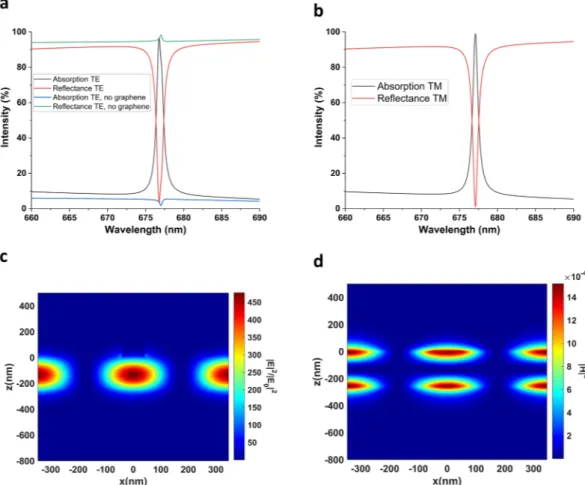
gold is modeled by ellipsometric measurements. The absorption spectrum for Device II with its optimized param-eters is shown in Fig. 7a,b, under s and p-polarized light, respectively. In these figures, we see a very sharp reso-nance at 676.8 nm (677 nm) with the absorption strength of 98% (99.2%) for s (p)-polarized light. The bandwidth
Figure 6. Structure of Device II, used to achieve perfect absorption by critically coupling graphene to excited
of the resonance for both TE and TM polarization is 0.8 nm, thus giving a very high Q-factor of about 850. Here, Q-factor is defined by Q = λ/Δλ. Figure 7a also demonstrates the absorption of Device II in the absence of graphene. The absorption without graphene is as low as 1%, because the layer thicknesses (including tSiO2) are
arranged carefully so that complete reflection occurs at resonance. When present, graphene is then responsible for the remaining 98% absorption as well as a slight blue-shift of GMR. Figure 7c,d demonstrate the localization of electric and magnetic field in the core region of the waveguide. Comparing Figs 7c,d to 3a–c shows that Device II stores larger energy in the core region, and the Q-factor achieved in Device II is higher as a result.
We now want to emphasize the key design strategy in achieving the ultra-narrow bandwidth. To achieve crit-ical coupling in a system where the external leakage rate is low, a very high energy storage, or equivalently, a very high-Q GMR in the resonant structure is needed43,45. Thus, the bandwidth is narrower in devices where graphene
is placed far away from the optical field confined by GMR. Although this strategy results in a narrower band-width, the necessity of creating a very high-Q GMR puts vigorous stress on the fabrication process. To increase the Q-factor of resonances in Device II, it is better to confine the mode to the core, i.e. increase neff. The narrower
resonances at larger core thicknesses and smaller unit-cell periods in Fig. 7c,d supports this argument. Therefore, the principal strategy in controlling the Q-factor is the thickness of the core region, tTa O2 5, and the unit-cell
peri-odicity, P. Increasing neff increases the energy storage inside the core region and decreases the leakage to the
graphene58. The critical coupling condition is then satisfied by the very high-Q GMR, and the resultant bandwidth
is low. This is the reason why tTa O2 5 in Device II is much higher than that of Device I, and P in Device II is smaller
than that in Device I. tPMMA and w are tailored accordingly to meet critical coupling condition.
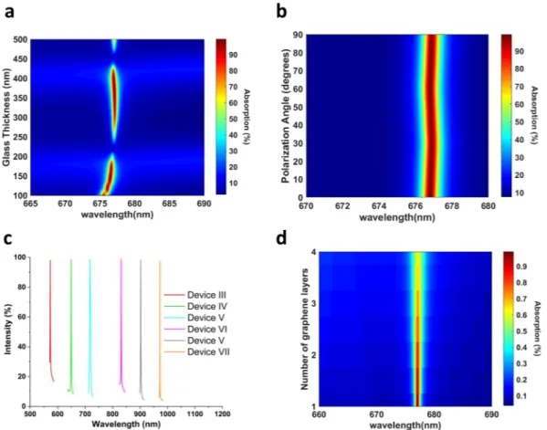
To examine the effect of the SiO2 thickness in the absorption spectrum, we varied it over a wide range from
100 nm to 500 nm, and the result is shown in Fig. 8a. The key observation is that the absorption spectrum shows maxima and minima that are periodic with λ/2nSiO2, λ being the resonance wavelength. This is consistent with the results reported in refs25,46 and it is because of the phase-shift introduced by the SiO
2 layer and the FP modes
defined by it46. Another reason may be that the system evolves from critical coupling to overcoupling or
under-coupling, as altering glass thickness changes external leakage rate43, while the intrinsic loss rate remains almost
the same. An interesting observation is that glass thickness starts having an effect on resonance wavelength below a certain value. Besides this, when tSiO2 is close to the value resulting in absorption maxima, an increase in it
causes the bandwidth to increase. This is because the external leakage rate controls the bandwidth of absorption, described by Eq. 9.
Figure 7. Achieving perfect absorption by critically coupling guided-mode to graphene. Absorption spectrum
of Device II under (a) s-polarized, (b) p-polarized light. (c) |E|2/|E0|2 at XZ plane during resonance (d) |H|2 at
www.nature.com/scientificreports/
We inspected the polarization-independence of Device II, and the result is shown in Fig. 8b. In terms of the absorption strength, Device II shows slightly more polarization dependence than Device I. This is because, as the Q-factor of GMR is increased, meeting the critical coupling condition becomes stricter. Hence, the spectrum becomes more sensitive to the energy stored in the GMR. Slight variations in this energy can then disturb the critical coupling condition. Nevertheless, the absorption strength is still above 98% for all source angles, and the spectral position of resonance shows even less dependence on polarization. It is worthwhile to mention that the proposed structure cannot become polarization insensitive if the thin absorbing film is inherently anisotropic. An example for such a case would be phosphorene. In that case, the puckered configuration of phosphorene and the resulting anisotropy68 means that although the grating has 60° rotational symmetry, overall structure will not
have this feature.
The sensitivity of GMR to geometrical parameters gives Device II a great tunability in visible and NIR ranges. As a general guideline, the resonance can be red-shifted by an increase in tTa O2 5 and P, as in Fig. 7c,d. To decrease
the bandwidth, on the other hand, it is necessary to increase tTa O2 5 but decrease P, so that neff increases. tSiO2 is
picked accordingly to satisfy the critical coupling condition. Tuning of the GMR between 570 nm and 970 nm is shown in Fig. 8c. Device V in Fig. 8c is also an example of achieving multiple resonances from a single device. Device VII has an FWHM of only 0.5 nm, reaching an ultra-high Q-factor of approx. 2000. This is because graphene’s intrinsic absorption starts declining for wavelengths larger than 850 nm. The main drawback of our design in terms of tunability is that the intrinsic absorption of gold starts to be significant below ~600 nm. Therefore, although 100% absorption can be achieved below 550 nm easily, it is not graphene that is responsible for perfect absorption. Replacing the gold mirror with dielectric Bragg mirror can extend the perfect absorption in graphene in the visible range. Aluminum and silver can also be used as the back-mirror, as their absorption starts dominating at significantly smaller wavelengths, but the latter’s degradation in air is an issue to consider in fabrication process69.
We now accentuate the fundamental difference in the design methodologies of Device I and Device II. In Device I, the effective mode refractive index had to be kept at an intermediate value because too high or too weak confinement of the mode to the core was detrimental to absorption. However, in Device II we could be able to confine the mode as much as we can to the core, without considering transmitted losses, and critical coupling gives both perfect absorption and ultra-narrow bandwidth. The same design strategy in Device I would result in absorption and transmission approaching each other, and to 50%.
Figure 8. Absorption spectrum of Device II under varying (a) Glass thickness, tSiO2, (b) Polarization angle. (c)
Tuning the perfect absorption in the visible and mid-infrared ranges. tTa O2 5 = 160, 180, 300, 300, 400 nm;
P = 350, 400, 550, 500, 600 nm, tSiO2 = 380, 420, 260, 240, 540 nm for Devices 3, 4, 5, 6 and 7, respectively.
Up to now, this paper dealt with achieving perfect absorption with monolayer graphene. However, the con-cept of critical coupling is general and can be applied to other 2D materials, such as transition-metal dichalco-genides (TMDs), and multilayer graphene to yield perfect absorption with polarization insensitivity. To explain the effect of multilayer graphene, we increased the number of graphene layers in the simulations, and the result is demonstrated in Fig. 8d. The result of the addition of graphene layers is the decrease in absorption strength and the broadening of the absorption peak, without a change of resonance wavelength. All of these results are well-expected from coupled mode theory and Eq. 9. Increasing the number of graphene layers would not affect the external leakage rate of the resonator as it is controlled by the mode confinement to the core. However, the intrinsic absorption rate would increase and the match between the external leakage rate and intrinsic absorption rate would then be lost. So, increasing the graphene layers drives the resonator towards undercoupling66. Other
2D materials, such as transition-metal dichalcogenides show stronger light-matter interaction than graphene, in the order of 10% in the visible range70. Compared to the intrinsic 2.3% absorption in graphene, larger intrinsic
absorption in TMDs would mean satisfying the critical coupling condition requires a larger external leakage rate for matching. So, the absorption spectrum associated with them are inherently broader. From the viewpoint of light sensing or biosensing applications, using graphene is advantageous due to narrower bandwidth. However, the broader resonances associated with TMDs would mean a larger average absorption in the visible spectrum and the presence of a direct bandgap combined with it makes monolayer TMDs a great candidate for photode-tection and photovoltaics71,72.
The experimental verification of this work starts with the fabrication flow of choosing a Silicon or quartz substrate. Choice of substrate does not affect Device II as the thick gold layer means that there will be insignifi-cant amount of light reaching there. Thus, a thin (5–10 nm) Titanium layer can be coated beneath gold for better adhesion, without affecting the optical properties. After that gold, SiO2 and Ta2O5 can all be coated by Physical
Vapor Deposition (PVD) methods such as sputtering. Chemical Vapor Deposition (CVD) grown graphene can be transferred and PMMA grating structure can be realized by electron-beam lithography. The numerical findings of this paper propose that the core thickness and the unit-cell periodicity are the most important factors in deter-mining the resonance position and bandwidth, as well as the absorption strength. This makes the precise deposi-tion of Ta2O5 and electron-beam lithography of the 2D grating structure the most important steps. The fabricated
samples can be characterized by Fourier Transform Infrared Spectroscopy (FTIR) technique for the resonances in NIR, whereas confocal microscopy can be utilized for resonances in visible range. We believe that the deviations of experimental findings from theoretical results can be restricted to a controlled region by the physical laws and explanations presented in this paper.
Conclusions
In conclusion, the enhancement of light-graphene interaction is numerically analyzed in this paper and the near-perfect polarization insensitivity of proposed design to incident light is verified. Our novel sub-wavelength dielectric grating excites the guided modes of an asymmetric dielectric slab waveguide. The critical coupling of the guided mode resonances to graphene resulted in perfect light absorption that is tunable by structural parame-ters in the visible and NIR ranges. The bandwidth of the resonance, 0.8 nm resulted in a very high Q-factor of 850. To the best of our knowledge, this bandwidth is smaller than all of the relevant device proposals with sub-micron thickness. Overall, our simple yet robust, and easy-to-fabricate device holds great promise in ultra-sensitive color detection and design of advanced photodetectors. Our future work will focus on the fabrication of the device and extending the tunability range of the guided-mode resonance.
References
1. Novoselov, K. S. et al. Electric field effect in atomically thin carbon films. Sci. (New York, N.Y.), https://doi.org/10.1126/ science.1102896, 0410550 (2004).
2. Bonaccorso, F., Sun, Z., Hasan, T. & Ferrari, A. C. Graphene photonics and optoelectronics. Nat. Photonics, https://doi.org/10.1038/ nphoton.2010.186, 1006.4854 (2010).
3. Novoselov, K. S. et al. Two-dimensional gas of massless Dirac fermions in graphene. Nat., https://doi.org/10.1038/nature04233.
0509330 (2005).
4. Geim, A. K. & Novoselov, K. S. The rise of graphene. Nat. Mater., https://doi.org/10.1038/nmat1849, 0702595v1 (2007). 5. He, J., Chai, Y. & Liao, L. Focus on 2D materials beyond graphene. https://doi.org/10.1088/1361-6528/aa98b9 (2018).
6. Manzeli, S., Ovchinnikov, D., Pasquier, D., Yazyev, O. V. & Kis, A. 2D transition metal dichalcogenides. https://doi.org/10.1038/ natrevmats.2017.33 (2017).
7. Miao, X. et al. High efficiency graphene solar cells by chemical doping. Nano Lett., https://doi.org/10.1021/nl204414u, 1209.0432 (2012).
8. Bernardi, M., Palummo, M. & Grossman, J. C. Extraordinary sunlight absorption and one nanometer thick photovoltaics using two-dimensional monolayer materials. Nano Lett., https://doi.org/10.1021/nl401544y (2013).
9. Xu, J.-L. et al. Graphene saturable absorber mirror for ultra-fast-pulse solid-state laser. Opt. Lett., https://doi.org/10.1364/ OL.36.001948 (2011).
10. Tan, W. D. et al. Mode locking of ceramic Nd:yttrium aluminum garnet with graphene as a saturable absorber. Appl. Phys. Lett.,
https://doi.org/10.1063/1.3292018 (2010).
11. Bao, Q. et al. Atomic layer graphene as saturable absorber for ultrafast pulsed lasers. Adv. Funct. Mater., https://doi.org/10.1002/ adfm.200901007, 0910.5820 (2009).
12. Mueller, T., Xia, F. & Avouris, P. Graphene photodetectors for high-speed optical communications. Nat. Photonics, https://doi. org/10.1038/nphoton.2010.40, 1009.4465 (2010).
13. Liu, C. H., Chang, Y. C., Norris, T. B. & Zhong, Z. Graphene photodetectors with ultra-broadband and high responsivity at room temperature. Nat. Nanotechnol., https://doi.org/10.1038/nnano.2014.31, 1512.00567 (2014).
14. Park, H., Rowehl, J. A., Kim, K. K., Bulovic, V. & Kong, J. Doped graphene electrodes for organic solar cells. Nanotechnol., https:// doi.org/10.1088/0957-4484/21/50/505204 (2010).
15. Wang, X., Zhi, L. & Müllen, K. Transparent, conductive graphene electrodes for dye-sensitized solar cells. Nano Lett., https://doi. org/10.1021/nl072838r, 0410550 (2008).
www.nature.com/scientificreports/
16. Bae, S. et al. Roll-to-roll production of 30-inch graphene films for transparent electrodes. Nat. Nanotechnol., https://doi.org/10.1038/ nnano.2010.132, 0912.5485 (2010).
17. Liu, M. et al. A graphene-based broadband optical modulator. Nat., https://doi.org/10.1038/nature10067, 1410.5318 (2011). 18. Li, Z. & Yu, N. Modulation of mid-infrared light using graphene-metal plasmonic antennas. Appl. Phys. Lett., https://doi.
org/10.1063/1.4800931 (2013).
19. Hong, S. Y. et al. Optical third-harmonic generation in graphene. Phys. Rev. X, https://doi.org/10.1103/PhysRevX.3.021014, 1301.1697 (2013).
20. Vincenti, M. A., De Ceglia, D., Grande, M., D’Orazio, A. & Scalora, M. Third-harmonic generation in one-dimensional photonic crystal with graphene-based defect. Phys. Rev. B - Condens. Matter Mater. Phys. 89, 1–6, https://doi.org/10.1103/PhysRevB.89.165139
(2014).
21. Gao, W., Shu, J., Qiu, C. & Xu, Q. Excitation of plasmonic waves in graphene by guided-mode resonances. ACS Nano 6, 7806–7813,
https://doi.org/10.1021/nn301888e (2012).
22. Zhan, T. R., Zhao, F. Y., Hu, X. H., Liu, X. H. & Zi, J. Band structure of plasmons and optical absorption enhancement in graphene on subwavelength dielectric gratings at infrared frequencies. Phys. Rev. B - Condens. Matter Mater. Phys., https://doi.org/10.1103/ PhysRevB.86.165416 (2012).
23. Zhu, X. et al. Experimental observation of plasmons in a graphene monolayer resting on a two-dimensional subwavelength silicon grating. Appl. Phys. Lett., https://doi.org/10.1063/1.4799173, 1301.3250 (2013).
24. Christensen, J., Manjavacas, A., Thongrattanasiri, S., Koppens, F. H. L. & García De Abajo, F. J. Graphene plasmon waveguiding and hybridization in individual and paired nanoribbons. ACS Nano, https://doi.org/10.1021/nn2037626 (2012).
25. Thongrattanasiri, S., Koppens, F. H. L. & García De Abajo, F. J. Complete optical absorption in periodically patterned graphene. Phys.
Rev. Lett. 108, 1–5, https://doi.org/10.1103/PhysRevLett.108.047401. 1106.4460 (2012).
26. Zhao, B. & Zhang, Z. M. Strong Plasmonic Coupling between Graphene Ribbon Array and Metal Gratings. ACS Photonics, https:// doi.org/10.1021/acsphotonics.5b00410 (2015).
27. Novoselov, K. S. et al. A roadmap for graphene. https://doi.org/10.1038/nature11458, 0802.2267 (2012).
28. Kim, K., Choi, J. Y., Kim, T., Cho, S. H. & Chung, H. J. A role for graphene in silicon-based semiconductor devices, https://doi. org/10.1038/nature10680, 1205.4050 (2011).
29. Furchi, M. et al. Microcavity-integrated graphene photodetector. Nano Lett., https://doi.org/10.1021/nl204512x, 1112.1549 (2012). 30. Ferreira, A., Peres, N. M., Ribeiro, R. M. & Stauber, T. Graphene-based photodetector with two cavities. Phys. Rev. B -Condens.
Matter Mater. Phys., https://doi.org/10.1103/PhysRevB.85.115438, 1201.3175 (2012).
31. Fang, Z. et al. Graphene-antenna sandwich photodetector. Nano Lett., https://doi.org/10.1021/nl301774e (2012).
32. Grande, M. et al. Fabrication of doubly resonant plasmonic nanopatch arrays on graphene. Appl. Phys. Lett., https://doi. org/10.1063/1.4810785 (2013).
33. Zhu, X. et al. Enhanced light-matter interactions in graphene-covered gold nanovoid arrays. Nano Lett., https://doi.org/10.1021/ nl402120t, 1306.1555 (2013).
34. Cai, Y., Zhu, J. & Liu, Q. H. Tunable enhanced optical absorption of graphene using plasmonic perfect absorbers. Appl. Phys. Lett. 106, https://doi.org/10.1063/1.4906996 (2015).
35. Jahani, S. & Jacob, Z. All-dielectric metamaterials. https://doi.org/10.1038/nnano.2015.304, arXiv:1001.3711v1 (2016).
36. Rosenblatt, D., Sharon, A. & Friesem, A. A. Resonant grating waveguide structures. IEEE J. Quantum Electron., https://doi. org/10.1109/3.641320 (1997).
37. Magnusson, R. & Wang, S. S. New principle for optical filters. Appl. Phys. Lett., https://doi.org/10.1063/1.107703 (1992).
38. Wang, S. S., Moharam, M. G., Magnusson, R. & Bagby, J. S. Guided-mode resonances in planar dielectric-layer diffraction gratings.
J. Opt. Soc. Am. A, https://doi.org/10.1364/JOSAA.7.001470 (1990).
39. M. G.Moharam & T. K.Gaylord. Rigorous coupled-wave analysis of planar-grating diffraction. J. Opt. Soc. Am., https://doi. org/10.1364/JOSA.71.000811 (1981).
40. Hessel, A. & Oliner, A. A. A New Theory of Wood’s Anomalies on Optical Gratings. Appl. Opt., https://doi.org/10.1364/AO.4.001275
(1965).
41. Tamir, T. Leaky waves in planar optical waveguides. Nouvelle Revue d’Optique, https://doi.org/10.1088/0335-7368/6/5/304 (1975). 42. Halir, R. et al. Waveguide sub-wavelength structures: A review of principles and applications. Laser Photonics Rev. 9, 25–49, https://
doi.org/10.1002/lpor.201400083 (2015).
43. Piper, J. R. & Fan, S. Total Absorption in a Graphene Monolayer in the Optical Regime by Critical Coupling with a Photonic Crystal Guided Resonance. ACS Photonics 1, 347–353, https://doi.org/10.1021/ph400090p (2014).
44. Long, Y. et al. Dually guided-mode-resonant graphene perfect absorbers with narrow bandwidth for sensors. J. Phys. D: Appl. Phys.
49, 4–9, https://doi.org/10.1088/0022-3727/49/32/32LT01 (2016).
45. Long, Y., Shen, L., Xu, H., Deng, H. & Li, Y. Achieving ultranarrow graphene perfect absorbers by exciting guided-mode resonance of one-dimensional photonic crystals. Sci. Reports 6, 2–9, https://doi.org/10.1038/srep32312 (2016).
46. Grande, M. et al. Graphene-based perfect optical absorbers harnessing guided mode resonances. Opt. Express 23, 21032, https://doi. org/10.1364/OE.23.021032. 1410.2102 (2015).
47. Grande, M. et al. Graphene-based absorber exploiting guided mode resonances in one-dimensional gratings. Opt. Express 22, 31511,
https://doi.org/10.1364/OE.22.031511. 1410.2102 (2014).
48. de Ceglia, D. et al. Tuning infrared guided-mode resonances with graphene. J. Opt. Soc. Am. B 33, 426, https://doi.org/10.1364/ JOSAB.33.000426 (2016).
49. Guo, C. C. et al. Experimental Demonstration of Total Absorption over 99% in the Near Infrared for Monolayer-Graphene-Based Subwavelength Structures. Adv. Opt. Mater., https://doi.org/10.1002/adom.201600481 (2016).
50. Fan, Y. S. et al. Monolayer-graphene-based perfect absorption structures in the near infrared. Opt. Express 25, 13079, https://doi. org/10.1364/OE.25.013079 (2017).
51. Kumar, M., Tervo, J., Kaplas, T. & Svirko, Y. Graphene-enhanced waveguide-resonance gratings. J. Nanophotonics, https://doi. org/10.1117/1.JNP.10.012518 (2016).
52. Ghobadi, A. et al. Visible light nearly perfect absorber: an optimum unit cell arrangement for near absolute polarization insensitivity.
Opt. Express, https://doi.org/10.1364/OE.25.027624 (2017).
53. Palik, E. Handbook of Optical Constants of Solids. https://doi.org/10.1016/B978-012544415-6.50143-6 (1997).
54. Hanson, G. W. Dyadic Green’s functions and guided surface waves for a surface conductivity model of graphene. J. Appl. Phys.,
https://doi.org/10.1063/1.2891452, 0701205 (2008).
55. Fan, S. & Joannopoulos, J. D. Analysis of guided resonances in photonic crystal slabs. Phys. Rev. B - Condens. Matter Mater. Phys.,
https://doi.org/10.1103/PhysRevB.65.235112, 1605.09167 (2002).
56. Long, Y. Effects of metal electrode reflection and layer thicknesses on the performance of inverted organic solar cells. Sol. Energy
Mater. Sol. Cells, https://doi.org/10.1016/j.solmat.2009.12.017 (2010).
57. Pettersson, L. A. A., Roman, L. S. & Inganas, O. Modeling photocurrent action spectra of photovoltaic devices based on organic thin films. J. Appl. Phys., https://doi.org/10.1063/1.370757 (1999).
58. Yariv, A. & Yeh, P. Photonics: optical electronics in modern communications, 0195106261, arXiv: 1011.1669v3 (2007).
59. Orfanidis, S. J. Electromagnetic Waves and Antennas. Media, https://doi.org/10.1016/B978-075064947-6/50011-3, arXiv:1011.1669v3 (2004).
60. Born, M. & Wolf, E. Principles of Optics 7th edition, https://doi.org/10.1016/S0030-3992(00)00061-X. arXiv:1011. 1669v3 (1999). 61. Rubio-Mercedes, C., Rodriguez-Esquerre, V., Lima, I. & Hernandez-Figueroa, H. Analysis of straight periodic segmented waveguide
using the 2-D finite element method. J. Light. Technol., https://doi.org/10.1109/JLT.2014.2321047 (2014).
62. Joannopoulos, J. J. D., Johnson, S., Winn, J. N. J. & Meade, R. R. D. Photonic crystals: molding the flow of light, https://doi. org/10.1063/1.1586781, arXiv:1011.1669v3 (2008).
63. Rytov, S. M. Electromagnetic properties of a finely stratified medium. Sov. Phys. JETP (1956).
64. Marcuse, D. Theory of dielectric optical waveguides, https://doi.org/10.1017/CBO9781107415324.004, arXiv:1011.1669v3 (2013). 65. Chong, Y. D., Ge, L., Cao, H. & Stone, A. D. Coherent perfect absorbers: Time-reversed lasers. Phys. Rev. Lett., https://doi.
org/10.1103/PhysRevLett.105.053901, 1003.4968 (2010).
66. Haus, H. Waves and Fields in Optoelectronics. https://doi.org/10.1080/716099690 (1985).
67. Yariv, A. Critical coupling and its control in optical waveguide-ring resonator systems. IEEE Photonics Technol. Lett., https://doi. org/10.1109/68.992585 (2002).
68. Dhanabalan, S. C. et al. Emerging Trends in Phosphorene Fabrication towards Next Generation Devices. https://doi.org/10.1002/ advs.201600305 (2017).
69. Naik, G. V., Shalaev, V. M. & Boltasseva, A. Alternative plasmonic materials: Beyond gold and silver, https://doi.org/10.1002/ adma.201205076, 1109.5444 (2013).
70. Li, Y. et al. Measurement of the optical dielectric function of monolayer transition-metal dichalcogenides: MoS2, Mo S e2, WS2, and WS e2. Phys. Rev. B - Condens. Matter Mater. Phys. 90, 1–6, https://doi.org/10.1103/PhysRevB.90.205422 (2014).
71. Ponraj, J. S. et al. Photonics and optoelectronics of two-dimensional materials beyond graphene. Nanotechnol., https://doi. org/10.1088/0957-4484/27/46/462001 (2016).
72. Dhanabalan, S. C., Ponraj, J. S., Zhang, H. & Bao, Q. Present perspectives of broadband photodetectors based on nanobelts, nanoribbons, nanosheets and the emerging 2D materials. https://doi.org/10.1039/c5nr09111j (2016).
Acknowledgements
Authors acknowledge financial support from Scientific and Technological Research Council of Turkey (TUBITAK) and DPT-HAMIT under the Project Nos. 113E331, 114E374, and 115F560. One of the authors (E.O.) also acknowledges partial support from the Turkish Academy of Sciences (TUBA).
Author Contributions
First Author (D.U.Y.) carried out the modeling, theoretical study, design and simulations. A.G. helped in the modeling and simulations. E.O. supervised the study. All of the authors contributed in the results discussions and paper writing.
Additional Information
Supplementary information accompanies this paper at https://doi.org/10.1038/s41598-018-33609-2.
Competing Interests: The authors declare no competing interests.
Publisher's note: Springer Nature remains neutral with regard to jurisdictional claims in published maps and
institutional affiliations.
Open Access This article is licensed under a Creative Commons Attribution 4.0 International
License, which permits use, sharing, adaptation, distribution and reproduction in any medium or format, as long as you give appropriate credit to the original author(s) and the source, provide a link to the Cre-ative Commons license, and indicate if changes were made. The images or other third party material in this article are included in the article’s Creative Commons license, unless indicated otherwise in a credit line to the material. If material is not included in the article’s Creative Commons license and your intended use is not per-mitted by statutory regulation or exceeds the perper-mitted use, you will need to obtain permission directly from the copyright holder. To view a copy of this license, visit http://creativecommons.org/licenses/by/4.0/.