This work has been supported by European Union FP7 Project WiMAGIC under grant number 215167. The authors would like to acknowledge the support provided by “Rinicom Ltd”
Novel Predistortion Algorithm for OFDMA
Saqib Ali1, Garik Markarian2, Erdal Arikan31,2Dept. of Communication Systems, Lancaster University, UK 1[email protected], 2[email protected]
3Dept of E&E Engineering Bilkent University, Turkey 3[email protected]
Abstract- The RF amplifier in a wireless communication system is usually non-linear in nature. If such an amplifier is used in OFDMA based systems, it will cause serious degradation. This degradation will be both in terms of the reduction in BER and the generation of out of band noise. In this paper we have worked on the linearization method of the amplifier. This work is on a hybrid methodology, in which estimation of the model is performed in frequency domain and compensation is performed in time domain. The downlink preamble of the IEEE802.16e system is used here for the estimation purpose. The results for the suppression of spectra are shown at the end.
Keywords- High power amplifier, Non-linearity, OFDMA, WiMAX, 802.16e, 802.16m.
I. INTRODUCTION
The RF amplifiers, which are used in general at the wireless transmitter, are nonlinear in nature. An OFDMA based system, which has a high peak to average power ratio, will be seriously impaired in terms of performance by the use of such amplifiers. In this scenario, most of the signal is amplified in the linear region, while the peaks get amplified in the non-linear portion of the amplifier. This nonlinear amplification results in the reduction of the bit error rate at the receiver and the generation of out of band noise in the transmitted signal.To mitigate this effect, linear amplifiers are used in practice. These amplifiers are expensive, therefore there is a need for a low cost, and wide spread solution. Another way is to make the transfer function of the amplifier as linear as possible, by using some linearization circuit. This linearization can be done in either analogue or digital domain. Due to the advancements in computers in the recent era, there has been a shift in the techniques from analogue to digital domain. These days it is an urge to make such a linearization possible in the digital baseband domain. In the currently being developed standard i.e. the IEEE 802.16m, there has already been put an emphasis on the linearization of the amplifier. In the standard linearization in digital domain, has been placed as a requirement. This digital linearization module in the later text will be referred as the “predistorter”. This predistorter distorts the signal in such a way, that when this signal is passed through the amplifier, the combined response at output of the amplifier appears to be a signal that would have been amplified by a linear amplifier. It is indeed a challenge for the designer to make this cumulative response as close to the clipped linear amplifier response, as much as possible. It should be noted here that the clipping effect happens due to the supply voltage available to the amplifier
In this paper we have proposed a new approach for the linearization of power amplifier. We have simulated a
transmission system, which is designed around the requirements drawn in the IEEE 802.16m EMD [1]. In particular we have used an OFDMA system with 2048 subcarriers. The Rapp model with s=2 is considered here as the amplifier model. Where, “s” is usually called as the “knee factor”, which determines the smoothness of the response. As per requirement, the compensated amplifier response needs to compared to the RAPP, s= 30 model [1].
II. PROPOSED SOLUTION
In the literature there exist various methods which propose linearization solution for OFDMA signals. These techniques range from the usage of simple estimators to the complex techniques, such as the neural networks, genetic algorithms. In [2]&[3] predistortion solutions for single carrier systems are focused. Whereas [4],[5],[6]&[7] discuss the predistortion for the OFDM(A) systems. In [8]&[9] neural network and genetic algorithm based predistortion is proposed respectively. It is worth noting that predistortion for OFDM(A) system is different from single carrier systems. The major difference lies in the existence of two domains. Namely frequency and time domains. Keeping this in view there exist options for the deployment of predistorter in either domains. However all the references given above for the OFDM(A) systems are focused on time domain predistortion. The only work to the author’s knowledge is done fully around the frequency domain compensation is [10]. In this paper we have mixed the above stated domains to propose a hybrid solution. In this approach we estimate the predistorter coefficients in the frequency domain, whereas they were used in the time domain. This mixed domain mitigation provide us with quite a good results in terms of the amplifier linearity and reduction in the out of band noise. As mentioned above the Rapp model, which is a behavioral model of a solid state amplifier will be used as an amplifier’s behavioral model, which is represented mathematically as, 1 2 2 ( ) ( ) ( ) 1 s s x t y t x t C = ⎛ ⎞ + ⎜ ⎟ ⎝ ⎠
(1)
Where “C” is the output saturation amplitude and “s” is the non-linearity constant/ knee factor. We have considered a normalized Rapp model with C=1 & s=2. Solid state amplifiers have a negligible distortion in phase, therefore the AM/PM function of the amplifier is considered as
(.) 0
φ = (2)
Thus the normalized amplifier model becomes:
(
4)
1/4( )
( )
1
( )
x t
y t
x t
=
+
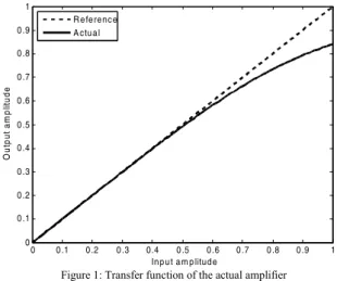
(3)The transfer function for this baseband model is shown below 0 0 .1 0 .2 0 .3 0.4 0 .5 0 .6 0 .7 0 .8 0 .9 1 0 0 .1 0 .2 0 .3 0 .4 0 .5 0 .6 0 .7 0 .8 0 .9 1 In p u t a m p litud e O ut pu t am pl it ude R e fe re nc e A ctu a l
Figure 1: Transfer function of the actual amplifier
The amplifier model in (3) can be represented by a power series expansion as below
5 9 13 17 21 25 ( ) 5 ( ) 15 ( ) ( ) ( ) - -4 32 128 195 ( ) 663 ( ) 4641 ( ) -2048 8192 65536 x t x t x t y t x t x t x t x t = + + +
"
(4)Whereas the analytical inverse of this amplifier model (which is an ideal predistorter) is represented as:
4 1/ 4 ( ) ( ) (1 ( ) ) y t x t y t = − (5)
Whose power series expansion is,
5 9 13 17 21 25 ( ) 5 ( ) 15 ( ) ( ) ( ) 4 32 128 195 ( ) 663 ( ) 4641 ( ) 2048 8192 65536 y t y t y t x t y t y t y t y t = + + + + + +
"
(6)Two points are worth noting here, 1) All the terms except power 4n+1 (where n= 0,1,2,3....) have vanished in the both of the expansions & 2) The magnitude of the coefficients of the two series is the same, whereas the only difference exists in the sign of the coefficients. This gives us an idea for the direct or an indirect calculation of the coefficients. This can be done by calculating the amplifier series coefficients and then changing their signs.
In the estimation phase the coefficients are calculated in the frequency domain. The equivalents of the terms in the time domain are calculated by using the convolution operator in the frequency domain. By using this technique the frequency domain convolution series can be represented as,
1
Y c X
=
1( )
+
c X X X X X
2( * *
∗ ∗
) ...
+
(7)The resultant gives the frequency domain equivalent of the power series expansion. The linear least square estimation is used to find the coefficients of the amplifier. The
1 ( * *X X X X X)
∗ ∗ is frequency domain equivalent of (x5).
compensation phase consists of the predistortion of the time domain signal (i.e. the signal after the IFFT operation) by using the calculated coefficients.
III. PREDISTORTION METHODOLOGY
The most important part of this whole setup is getting the accurate model of the amplifier. The amplifier needs to be probed by a known signal, such that nearly whole of the response is covered. In the IEEE 802.16e standard there are preambles defined for the downlink transmission. These preambles are transmitted at the start of each transmission burst. The main purpose for these is the symbol synchronization at the receiver. As this preamble is known to the transmitter, therefore it can also be used for identification of the amplifier response. The preamble signal needs to be boosted such that it covers most of the amplifiers transfer function. As we have used the parametric estimation method, an approximate value of the applied gain within a certain window will be sufficient to get a good model.
IV. ESTIMATION & COMPENSATION PHASE
During the estimation phase the predistorter is removed from the signal path. A preamble will be transmitted which will capture the response of the amplifier. It is assumed that the system is working in the TDD mode. (Receiver is
switched off during transmission in a TDD mode, and vice versa). A small change that is proposed from the standard
TDD is that when the transmitter is sending the preamble, receiver circuit in the transceiver is also connected. The transmitter sends the boosted preamble at the start of the burst. This preamble is captured by the receiver circuit at the same time. The frequency domain equivalent of the actual preamble and the looped back signal are calculated and sent to the estimation block. Based on the available information, the estimator calculates the coefficients of the predistorter. A block diagram which represents the slight change of TDD during the estimation phase is shown below:
Figure 2: The receiver is active during preamble transmission.
V. SIMULATION
In this simulation we have considered an OFDMA system with 2048 subcarriers, whose time domain, base band output gets amplified by an amplifier model. The model is approximated to 25th degree, and the boosting of the
preamble is considered to be within a window of 20 – 23 dB. The simulation will be performed for different output back off (OBO), where, the output back off is defined as follows
Posat OBO
Poavg
= (8)
We have approximated the predistorter with a power series expansion. The more the terms in the power series are, the
better the model approximation will be. As already mentioned, in the expansion of Rapp-2 model all the terms except those which have a power 4n+1 (where n= 0,1,2,3....) gets disappeared. Therefore we have considered an expansion up to 25th degree. The problem is reduced to find the coefficients for x x x x x x1, , ,5 9 13, 17, 21 and x terms only. The 25 predistorter which essentially is an inverse function of amplifier, can be represented by same power terms as are in the actual amplifier series [11].In the simulation, we get the OFDMA time domain symbol after performing the IFFT operation. These samples are then amplified by the model given in Eq. (1). the output of the amplifier is captured and its Fourier transform is taken. Using the Fourier equivalents of the amplifier’s input and output we find the approximate model by employing the linear least square estimation technique.
The real challenge with the whole setup is the generation of an accurate model. If we come up with a good model, the system can be linearized to a very good extent, which in return will suppress the noise caused by the non-linearity. As it has already been discussed that coefficients for some powers goes down to zero in the expansion. So we can remove those while estimating the model. This will result in the reduction of the computation involved in the matrix inversion.
Another important thing in the model estimation is the probing signal. The probing signal needs to be such that it covers the response of the amplifier. In the IEEE 802.16e standard [12], preambles for the downlink have been specified. The preamble is transmitted at the start of each downlink. Its main purpose is for frame synchronization at the receiver. As these are known entities, therefore they can also be used for the amplifier modeling. The good point about this preamble approach is, the transmitter need not to be stopped during the transmission for the estimation purpose. Therefore any change in the amplifier model can be easily accommodated at runtime.
In this study, we have considered 2048 subcarriers (IFFT size), 173 Left guard subcarriers and 172 right guard band subcarriers. The DC is suppressed to 0 in the resulting signal. Every 3rd subcarrier in preamble is modulated according to a value provided in the standard. This preamble sequence is described in Figure 4.
Figure 3: Downlink preamble structure
As an example one of the various preambles provided in standard is shown in the table below.
Table 1:
Preamble from the IEEE 802.16e standard
Preamble
A9F7 AC1B D0A4 BD69 4D3E DC29 91CC 3B2D 24BF 26A2 … 2346 F8DB 3702 02CD A25D 382D 4119 AAC6 76E3 20A9 38A9… 5762 C407 8689 B602 4E47 7F0E DA8F 5631 06F0 D70E BE3E 006F…
75B5 0B53 7D
The preamble shown above is the hexadecimal representation of the 568 binary values. Each binary digit represents the bits that will be used to modulate the subcarriers. These bits are then modulated according to the following formula:
{
}
{
}
1 4. 2. 2 Im Re PreamblePilotsModulated Wk PreamblePilotsModulated 0 ⎛ ⎞ = ⎜⎝ − ⎟⎠ = (9)It must be noted that the preamble needs to be well amplified, so that it can cover whole of the dynamic range. In our simulations we have used a boosting value in the range of 20-23 dB, which gives good results.
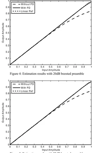
The linearization results for different preamble gain is shown below 0 0 .1 0 .2 0 .3 0 .4 0 .5 0 .6 0 .7 0 .8 0 .9 1 0 0 .1 0 .2 0 .3 0 .4 0 .5 0 .6 0 .7 0 .8 0 .9 1 In p u t A m p litu d e Ou tp u t A m p lit u d e W ith o u t P D W ith P D L in e a r R e f
Figure 4: Estimation results with 20dB boosted preamble
0 0 .1 0 .2 0 .3 0 .4 0 .5 0 .6 0 .7 0 .8 0 .9 1 0 0 .1 0 .2 0 .3 0 .4 0 .5 0 .6 0 .7 0 .8 0 .9 1 In p u t A m p litu d e O ut pu t A m pl it ude W ith o u t P D W ith P D L in e a r R e f
Figure 5: Estimation results with 23dB boosted preamble
VI. RESULTS
Figures 5&6, are the plots between the input and output amplitude of the amplifier. The dashed line beneath the straight lines, show the actual amplifier (Rapp-2 model) response. While the other two lines represent the reference and the compensated responses respectively. It can be observed that the two lines are hardly separable. The only separation between these two is distinguishable, when the input amplitude gets above 0.9. The very reason for this is the modeling error.
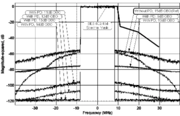
Impact on the spectrum of the output signal for various OBOs has been studied. A comparative plot is presented in figure 7. In this figure the reference is taken as a 15dB OBO amplifier response, without any compensation. The compensated response (with predistorter) for various OBOs [9,10,11,12,13 & 14 dB], is compared with the reference to provide an insight of the improvement in spectral characteristics. It is noteworthy that the non-linearity has caused the nulls to rise in an umbrella like manner. This unwanted rising of nulls causes a problem when more than
one system are working together. According to the FCC [13], there exists a restriction for the adjacent channel interference. This is a requirement, which the WiMAX systems need to adhere to. In the same figure the bold reference mask is provided. This mask is taken from the IEEE 802.16d standard requirement [10].
Figure 7: Spectrum for various OBO with PD as compared to without PD at 15dB
Figure 8 is a spectrum plot at 15dB OBO. In this case the back off is quite high, therefore after predistortion, the nulls subcarriers are well suppressed. In figure 9 the amplitude of the time domain samples are also shown. The peaks are well below the input saturation point of amplitude. Likewise the figure 8(a, b, c, d, e, f, g & h) shows the spectral response and the corresponding time domain waveforms for 15dB, 12dB, 10dB & 9dB back off.
There is one interesting point which needs to be noticed in Fig. 8(h); the peaks have now started crossing the input saturation amplitude. These peaks get clipped off by the amplifier. This clipping phenomenon has also started affecting the output spectrum. In short at this OBO both the nonlinearity of the amplifier and the clipping are playing their roles.
The performance of the predistorter, in terms of the null suppression is shown in table 2:
Table 2:
Suppression of the null subcarriers, at the edges of the band.
Sr.No. OBO (dB)
Relative suppression of nulls at the band edges
(dB)
1 15 60
2 12 60
3 10 38
4 9 20
The values represent the difference between powers of the null carriers at the edges of the band. As an example the 60dB suppression is observed for the 15dB OBO(figure 8), while 20dB suppression is observed for the case of 9dB OBO.
VII. SUMMARY & BENIFITS
The hybrid method has been used in this study. As discussed earlier, this method performs the estimation in frequency domain and compensation in time domain. Using the two domains allows for a better control of the problem. The frequency domain estimation allows for the coefficient
calculation, while having a through insight to the spectral characteristics of the output signal. While, the time domain compensation allows for the direct compensation of the amplifier. The overall benefit is observed in terms of good linearization and better out of band noise suppression.
VIII. FUTURE DIRECTION
In the study it is observed that the hybrid predistortion methodology eliminates the effect of the non-linearity to a reasonable extent. However at lower back off, the peaks of OFDMA signal start crossing the amplifiers saturation point, and eventually get clipped due to the amplifier’s power supply. Therefore for an OFDMA system working at low back off, has both nonlinearity of the amplifier and the PAPR as the cause of the distortions. Although our emphasis was mainly around generating an ideal predistorter, but it is observed that this compensation will work well if performed together with the PAPR reduction methods.
To take this study one step ahead it is suggested that work needs to be done on the joint mitigation of PAPR and the HPA nonlinearity for OFDMA signals, where both the PAPR and amplifier linearization can be done simultaneously.
IX. REFERENCES
[1] J. Zhuang, L. Jalloul, R. Novak, and J. Park, "IEEE 802.16m Evaluation Methodology Document (EMD)," IEEE 26th November 2008.
[2] H. W. Kang, Y. S. Cho, and D. H. Youn, "On compensating nonlinear distortions of an OFDM system using an efficient adaptive predistorter." vol. 47, 1999, pp. 522-526.
[3] A. N. D'Andrea, V. Lottici, and R. Reggiannini, "An application of amplitude and phase predistortion to OFDM systems," in Global
Telecommunications Conference, 2000. GLOBECOM '00. IEEE,
2000, pp. 1417-1421 vol.3.
[4] Y. Ding, Y. Liu, I. Nilkhamhang, and A. Sano, "Adaptive Linearization for Power Amplifier in OFDM Systems," 2006, pp. 751-754.
[5] M. G. Di Benedetto, M. G. Di Benedetto, and P. Mandarini, "An application of MMSE predistortion to OFDM systems
An application of MMSE predistortion to OFDM systems,"
Communications, IEEE Transactions on, vol. 44, pp. 1417-1420,
1996.
[6] E. Costa, M. Midrio, and S. Pupolin, "Impact of amplifier nonlinearities on OFDM transmission system performance." vol. 3, 1999, pp. 37-39.
[7] C. Ciochina, F. Buda, and H. Sari, "An Analysis of OFDM Peak Power Reduction Techniques for WiMAX Systems," in
Communications, 2006. ICC '06. IEEE International Conference on,
2006, pp. 4676-4681.
[8] R. Zayani and R. Bouallegue, "A Neural Network Pre-Distorter for the Compensation of HPA Nonlinearity: Application to Satellite Communications," 2007, pp. 465-469.
[9] R. Sperlich, "Adaptive power amplifier linearization by digital pre-distortion with narrowband feedback using genetic algorithms," 2005. [10] S. Ali, G. Markarian, and M. Al-Akaidi, "Frequency Domain Iterative
Compensation of High Power Amplifier Non-linearity," in Middle
Eastern Multiconference on Simulation and Modelling (MESM 2008)
Philadelphia University, Amman, Jordan: Eurosis, 2008.
[11] J. S. Frame, "Power Series Expansions for Inverse Functions." vol. 64: Mathematical Association of America, 1957, pp. 236-240. [12] Contributors, "IEEE 802.16e-2005 Standard," IEEE Task Group e
2005.
[13] FCC, "Amendment of Parts 1, 21, 73, 74 and 101 of the Commission's Rules to Facilitate the Provision of Fixed and Mobile Broadband Access, Educational and Other Advanced Services in the 2150-2162 and 2500-2690 MHz Bands." vol. FCC 04-258, FCC, Ed.: FCC, 2004.
Figure 8(a): Comparison between the spectral response of without
and with PD at 15dB OBO. Figure 8(b): Time domain waveform for 15dB OBO
Figure 8(c)8: Comparison between the spectral response of, without
and with PD at 12dB OBO Figure 8(d)9: Time domain waveform for 12dB OBO
Figure 8(e): Comparison between the spectral response of , without
PD and with PD at 10dB OBO Figure 8(f): Time domain waveform for 10dB OBO
Figure 8(g): Comparison between the spectral response of, without