Microfabricated Ultrasonic Transducers: Towards
Robust Models and Immersion Devices
I. Ladabanm;
X.
.Jin
,
H. T. Soh, F.
Pierre
t,
A.Atalart,
B.
T.
Khuri-Yakub
E.L.
Ginzton Lnboratory,Stunford Universitv,Stanford
CA 94305
t V w l m y rcholor /mm Ecole Namole Superieure, FRANCE:On lerrue during 1996 ,+om Bdkent Unxuers$ly, T U R K E Y
Pair of transducers is able to operate in Water at 4, 6 , and is biased appropriately and subjected to ultrasonic waves 8 M H z with a signal t o noise ratio of at least 48 d B . The significant detection currents are generated,
same transducer pair is shown t o o p e r a t e in air at 6 MHz. A model is introduced which highlights the signiflcant param- eters of transducer design. T h e model enabler the design of
optimized transducers. AU
SiNx
Ed
si02F3
Si I. INTRODUCTIONUltrasound is now used in a wide variety of applications
which can he characterized as either sensing modalities or Fig. 1 Schematic of one element of a MU?
actuating modalities. Sensing amlications include medical
fruitful applications of ultrasound remain unrealized. It is
often a lack of adequate transducers that precludes the*
Clean p-type Si wafer
retically interesting ultrasonic systems from materializing. Air-coupled ultrasonic inspections motivate the develop- ment of air transducers [l], 121, [3], (41, [S] and the advan- tages of limited diffraction beams motivate the realization of 2-dimensional transducer matrices 161. 171. 181.
Oxide growth
Although piezoelectric ceramics and engineering clever- ness have enabled a significant number of ultrasonic devices and systems, many modern applications would benefit from transducers based on a different Drinciole of actuation and
.
1 1.
1Nitride deposition
detection. Analyses of capacitive acoustic transducers have existed for many decades [g]. The use of capacitive trans- ducers for air-borne ultrasonics dates hack to the 1950's
[lo],
[ l l ] , and the first immersion version appeared in 1979 an advanced configuration of capacitive ultrasonic trans- [12]. Microfabricated ultrasonic transducers (MIJTs) are ducers. MUTs have been shown to be superior air trans-ducers [13], [14]. In this paper, we show that microma-
Nitride and oxide etch
sion transducers.
chilled ultrasonic transducers (MUTs) are viable as immer-
E-beam lithography
11. DEVICE DESCRIPTION A X D FABRIC.ATIOK
4
MUT consists of metalized silicon nitride membranes suspended abol-e heavily doped silicon hulk. A schematicof one element of the device is shown in Figure 1. A trans- Fig. 2. Majm Steps of MET fabrication ducer consists of many such elements. IVhen a voltage
is placed between the metalized membrane and the bulk, is cleaned and a 1 pm oxide layer is grown with a wet
Metalization
oxidation process. A 3500 ?Ilityer of LPCVD nitride is then deposited. The residual stress of t,he nitride can he varied by changing the proportion of silane to ammonia during the deposition process. A pattern of etchant holes is then transferred to the wafer with a lithography process. The nitride
is
plasma etched and the sacrificial oxide is removed with HF. A second 2500 Alayer of LPCVD nitride is t.hen etchant holes.A
chrome adhesion layer and a 500a
film deposited on the released membranes, vacuum sealing the of gold are evaporated onto the wafer.111.
RESULTS
A single pair of MUTs was used to generate figures 3 -
6 . Furthermore, transmission was observed from 1
MHz
not the transducers. The figures were digitized with an 8 to 20
MHz,
with electronics limiting the frequency range, bit oscilloscope. A full scale signal contains undetectable noise, so the signal to noise ratio (SNR) is at least 48 dB. It is important to note that the MUTs were designed asaLi transducers. This accounts for the poor matching ev- idenced by multiple echos. The optimization parameters recommended in the following model would result in het- ter matching, yielding a greater overall system budget.
Fig. 3. Ttanernission with 4 cycles at 4 MHz.
I\-. D E V I C E b f O D E L I N G A X D OPTIXIIZhTIO?(
MUTs, the goal of the theory is t o arrive at an equiT-aIent In order t o facilitate the design of systems enabled bv circuit model of the transducer. The approach, as first sug- gested by Mason 191: is to find the mechanical impedance of former equivalent circuit.
the membrane in vacuum and then to insert it in a trans-
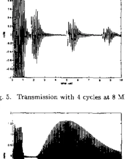
Fig. 3. Transrnirsion w i t h 4 cycles at 8 MHz
~I
*.
.
I..
%,..
,.
,II n
Fig. 6 . Toneburst transmission in air at 6 MHz
in vacuum. The membrane has a Young's modulus of Yo We consider a circular membrane of radius a operating and a Passion's ratio of a . In addition, the membrane is in tension T in units of N / m 2 . The differential equation governing the normal displacement z(r) of the membrane can be written as [15], [g]
+
T ) l :
V4z(r) - ItTV2s(r) -P
-lip- = 0 (l)where It is the membrane thickness, and P is the external uniform pressure applied to the membrane. The equation is derived from an energy formulation and the critical as- sumption is that the tension generated by a displacement z is small compared t o the tension T . Assuming a harmonic excitation at an angular frequency W , equation 1 is known
t o have a solution of the form
@ 4 r )
12(1- UZ) dtZ
Z ( T ) = AJo(klr)
+
BJo(kzr) - P / ( w 2 p l l ) (2)where A and B are arbitrary constants and
Jo()
is the zeroth order Bessel function of the first kind. If we use equation 2 to substitute for .(F) in equation 1 we find thatk , and k. must satisfy the characteristic equations:
(I5
+
Til2 2- , ;k:
+
4 ;
- W 2 = 0 (3) 12(1 - G - ) G (U, Cr)P
T.,
12(1 - U " ) . ' k , J + - k , - d = O-
U (4)Following Mason's notation n-e define
c =
(Yo
+
T)lj and d = -T
12(1 -G') P (5)
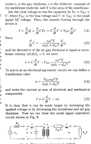
The quadratic formula then gives the solutions where 1, is the gap t,hickness, F is t,he dielectric constant of
the membrane material, and S is the area of the membrane.
( 6 ) L', where bbc is rhe bias voltage and V
<<
VK
is the small signal C !. voltage. Then, the current Howing through the device isk I =
11"-
Let the total voltage across the capacitor be VT = VDC+
kZ =
3
J z T L z
/
y
+
d ( 7 )r = - Q - c v T = C - L ' + V , ~ - C
d d d d (11)d t d l
d t d t
In order t o determine the constants A and B , two boundary
since
conditions are necessary. Physically resonable boundary d conditions at r = a are that z = 0, which implies that
&S d
flat (i.e. does not bend) at it's periphery. Both conditions
and &z = 0, which implies that the membrane is perfectly brme velocity (d,dt)l, = we have amount to stating that the membrane is perfectly bonded I =
c-v
d - LT Eor2Sto an infinitely rigid substrate. Lsing these conditions we dt DC (colt
+
€1,)2determine the constants
A
and B and find t,he displacement To of the membrane as-
dt
c
= ~( e o & +el,)*
;it"
(12) the membrane undergoes no displacement at it's periphery, and the derivative of air gap thickness is equal toD (13)
at an electrical equivalent circuit we can define a transformer ratio Z ( T ) =
-
wZplt' [
k d o ( k l a ) J l ( k ? a ) + k , J , ( k ~ a ) J o ( k z a ) k z J o ( k l r ) J l ( k ? a )+
k l J o ( k ~ r ) J 1 ( k l a ) - l1 V~/Dcro?S ( € 0 4+
C L ) Z n = (14)Fig, is a calculated plot of the displacement of a typical and write the current
as
sum of electrical and mechanical membrane various frequencies. For the simulation, values componentsused were a = 25 x It = 0.6 x P = 1, Yo =
3.2 x IO", u = 0.263,
T
= 280 x IO6, and p = 3270 (all inMKS
units).(8)
d
I = C - V - n U
dt
It is clear that n can be made larger by increasing the applied voltage or by decreasing the membrane and air gap thickness. Now we can draw the small signal equivalent circuit shown in Fig. 8.
(15)
p-,,
1'
6 2
_Is
4 , Fig. 8. Electrical equivalent circuit of hlUT
m
-,"*.l
timization of the hiCT structure. Parameters in the model The electrical equivalent circuit allows analysis and op-
p membrane excited by uniform pressure circuit. Furthermore, electrical matching circuits can be Mechanical impedance is defined as the ratio of force t o Thus, it is clear that the structural control offered by mi- velocity. Hence, the mechanical impedance of the mem- crofabrication coupled with the insight from the equivalent hrane per unit area, Z,, can be written as circuit model can yield optimized transducers.
pig. 7. calculated displacement as a function of frequency tor a 25 can be varied t o generate desired values in the equivalent included.
z,
=5
P (9) V . CONCLLXONWe have demonstrated that a oair of immersion MUTs -
- jwpltaklk?(kzJn(k,a)Jl(k?a)+...
~ w p 1 t a ~ l k z ( k 2 ~ o ( k l a ) ~ ~ (+ k l , ~ l ( k l a ) ~ o ( k z a ) ) k ~ ~ ) -
. .
, transducers were also able to send and receive airborne ul-can transmit ultrasound in water from 1 to 20 MHz. These trasound at 6 M H z . An equivalent circuit model has been presented which can be used to optimize MUT design. Op- timized MLTs should challenge piezoelectrics in many ap- ing the h fas ~a ~ plate capacitor, it's capacitance tages include high temperature oprration, ease of fabrica-
The electrical part of the analysis A ~ plications due to their numerous ~ ~ ~ ~ ,advantages. ~ ~SILT advan- ~ .
is given by tion of two dimensional arrays, and most, importantly, the
. . . j w p l t k l J l ( k l a ) . J n ( k y a ) )
. . .
2 ( k : + k S ) J l ( k , a ) J l ( k ? a )C = €OES ability to realize matched transducers by varying accessible colt + c l , ( l 0 ) parameters of the transducer.
VI. A C K Y O W L E D G ~ I E Y I
This work has been madP possible hy a grant from the United States Office of Naval Research
REFERENCES
Kcily, Stephen P , , Farlaw. Roger. dud Hayward. Oardon, ''.\p-
plications of through-air ultrasound for r a p d nde scanning in l h e
aerospace industry," lEEE Tronsaclion,~ on IJltmsonics, Fe-.
July 1996.
Chchagan. Anthony and Hayward. Gordon, "Characterization
of air-coupled transducecs," IEEE Tmnsmttons on Ultrasonics,
689. J u l y 1996.
Fenoelectncs, and F ~ e q u e n c y Control. YOI. 43, no. 4 , pp. 678- Hayward. Gordon and Gachagan. Anthony, " A n e v d u a t i m of
1-3 connectivity composite transducers forair~coupied ultrasonic
appilcatians," JournoI of the Auouslxcai Soriely o j America, vol.
99, no. 4 , pp. 2148-2167, Aprd i99fi
Manthey, W . , Kroemer, N.. and Magori, V., "Ultrason~c tran5-
ducers and transducer arrays for applications in air," Meas. Sci. Schindel, D. W. and Hutchins, D . A., "Applications of micro-
Technol., vol. 3, pp. 249-261, 1992
machined capacitance lransducers in air-coupled ultrasonics a n d nandestruclive evaluation.l( lEEE Transactions on Ultmsonics, Femelectrics. and Freouencv Conlml. vol. 42. no. l . DD. 51-58.
ciectrics, and Frequency Conlrol. vol. 43. 110. 4, pp. 581-591,
. .
January 1995.
Lu, Jian-yu and Greenieaf, Jamer F., "A sludy of t w e
dimensionai array transducers for iimited diffraction beams,"
IEEE ??onsaclions on Uitrasontcs. Ferroelectnes. and h.
. . .
quency Contml, "01. 41, no. 5 , pp. 724-739. September 1994. Goldberg, Richard L. and Smith, Stephen \V., "Multilayer
piezoelectric ceramics for two-dimensional array transducers,"
lEEE Transactions on Ullrasonics, Ferroeieclrrcs, and Fre-
quency Control, vol. 41, no. 5, pp. 761-771. September 1994. H y ~ l o p . J . E . , Bennet, J . T., and Hayward, G . , "An inveSligation
into the design of high frequency tw-dimensmnal arrays for "I-
traSonic imaging.," in Ultrnsonicr Symposium. Cannes. Rance,
Society, pp. 1515-1518.
1994, IEEE Ultrasonics, Ferroelectrics, and Frequency Control Warren P. Mason, Eleclmmechanicol Tmnsducem and Wove [lo] Khul, W., Schodder, G . R., and Schodder. F. K , "Condenser
Fillers, Van Nostrand, 1942.
tranmnitters and microphones with solid dielectric for airborne
~ltrasonics.l( A c u s l ~ n , vol. 4, pp. 520-532; 1954.
[ I l l K. Matzuwa, "[capacitive ultrasonic transducer]," J . Phy8. Soc. Japan, vol. 13, pp. 1533-43, 1958.
[l21 Cantreil, John H. and Heyman, Joseph S., "Broadband elec-
trostatic acoustic transducer for ultrasorlic measurements in liq- uids," Review of Scientific Imlruments, mi. 50, no. 1, pp. 31-33, January 1979.
[l31 L e a b a u m , Igal, Khuri-Yakub, Butrus T., and Spoliansky, Dim-
ItEl, "Micromachined ultrasonic transducers: 11.4 mhz l r a n ~
mission in air a n d more," Applted Phystcs Letters. vol. 68, no.
1 , pp. 7-9, January 1996.
[l41 L a r i a h u m , Igal, Khuri-Yakub, Butrus T., Spoiiansky. Dimitri,
and Halier, hlatthew l., "Micromachined ultrasonic transducers MUTs," in Ultrasonic8 Symposium, Levy, &I.. Schneider, S. C., and Mc.Avoy, B , R., Eds., Seattle, Washington, Yovember 1996.
DD. 501-504.
IEEE Ultrasonics, Ferroelectrics, and Frequency Control Society,
1151 j i h n William (Lord Rayieigh) Strutt, The Theory of Sound,
Irlacmiilan. 1877-78.