Enhanced coupling to microsphere resonances
with optical fibers
A. Serpengu¨zel
Department of Physics, Bilkent University, Bilkent, Ankara 06533 Turkey S. Arnold and G. Griffel
Microparticle Photophysics and Photonics Laboratories, Polytechnic University, 6 Metrotech Center, Brooklyn, New York 11201
J. A. Lock
Department of Physics, Cleveland State University, Cleveland, Ohio 44115 Received July 17, 1996
Morphology-dependent resonances (MDR’s) of polystyrene microspheres were excited by an optical fiber cou-pler. For optical elimination of the air–cladding interface at the optical fiber coupler surface, the microsphere was immersed in an index-matching oil. MDR’s were observed, even though the relative refractive index be-tween the microsphere and the oil was only 1.09. The observed MDR spectra are in good agreement with the generalized Lorenz–Mie theory and the localization principle. The scattering efficiency into each MDR is es-timated as a function of the impact parameter by means of generalized Lorenz–Mie theory. © 1997 Optical Society of America [S0740-3224(97)01804-3]
Key words: generalized Lorenz–Mie theory, guided waves, impact parameter, localization, microparticle, morphology-dependent resonances, photonic atom, scattering, whispering-gallery modes.
1. INTRODUCTION
Because of their unique optical properties, microspheres have enjoyed the attention of the optical spectroscopy community in recent years.1 Because of the spherical in-terface, three electromagnetic and quantum-electrodynamic effects take place in a microsphere. First, the microsphere acts as an optical cavity for specific wavelengthsl’s, which satisfy the morphology-dependent resonance (MDR) condition. MDR’s can be considered as standing waves, which may be decomposed into two coun-terpropagating waves traveling around the microsphere rim. Second, the transition cross sections in the micro-sphere can be larger than bulk transition cross sections, because of the modified density of final electromagnetic states.2 In the microsphere, the final states correspond to the microsphere cavity resonances, which are described by MDR’s. For a bulk sample, however, the final states are the continuum modes of an infinite system.3,4 Third, for plane-wave illumination, the internal intensity is con-centrated along the principal diameter near the front and the back surfaces of the microsphere. If the incident plane wave is resonant with a MDR (i.e., on resonance), there will be, in addition, a uniform intensity distribution within the rim of the microsphere in the volume deter-mined by the MDR.5 However, if an off-axis Gaussian beam is used at a resonant wavelength, the internal in-tensity is distributed only within the rim of the micro-sphere in the volume determined by the MDR and is no longer concentrated near the front and the back surfaces of the microsphere.6 Therefore a resonant off-axis
Gaussian beam excites the MDR’s of a microsphere more uniformly and more efficiently than does a plane wave. Even edge illumination with a focused beam excites MDR’s more efficiently than do plane waves.7,8 The off-axis Gaussian beam calculations have recently been real-ized by means of generalized Lorenz–Mie theory (GLMT).9,10 In this paper we report, for the first time to
our knowledge, exact formulas for the GLMT scattering cross sections to estimate the efficiency of the coupling (i.e., scattering) into the MDR’s.
2. EXPERIMENTAL SETUP AND
OBSERVATIONS
The first experimental realization of the off-axis Gaussian beam excitation geometry was performed by use of an op-tical fiber coupler (OFC).11 The frequency shift and the linewidth broadening of the MDR’s, which are both due to the OFC–microsphere interaction, were also studied.12 However, in these OFC–microsphere experiments, the cladding of the fiber was not index matched to the media surrounding the microsphere, so there was an optical in-terface at the OFC surface. In this paper we report, for the first time to our knowledge, the excitation of the MDR’s of a microsphere resting on the surface of an OFC whose surface has been wet with an index-matching oil to eliminate the air–fiber interface. The beam in the opti-cal fiber thereby effectively becomes the equivalent of a Gaussian beam with an infinitely long skirt length.
Figure 1 is a schematic of our experimental setup. A polystyrene (PS) microsphere with an approximate radius of 12 mm and a refractive index of 1.59 is placed on an OFC. The OFC is made from a single-mode optical fiber
(SMOF) with a core diameter of 3.8mm (refractive index, 1.462) and a cladding diameter of 125mm (refractive in-dex, 1.457). The cladding below the microsphere is shaved down to 0.7 mm. The SMOF mode has approxi-mately a Gaussian intensity profile and is doubly degen-erate with both horizontal and vertical polarizations. The OFC surface and the microsphere were wet with a few millimeters of index-matching oil (refractive index of 1.456, same as the cladding).
The excitation is provided by a tunable and linearly po-larized cw dye laser with optogalvanic calibration and a linewidth of 0.025 nm. The output of the dye laser is coupled to the SMOF with a microscope objective. Al-though the output of the dye laser was linearly polarized, the output of the SMOF was observed to be elliptically po-larized because of the fiber birefringence. Therefore the OFC provides both linear polarizations to the micro-sphere. The scattering from the microsphere was col-lected at 906 5° with a microscope objective (numerical aperture, 0.17) followed by a polarizer and was detected with a photomultiplier tube.
If one used plane-wave illumination, the image of the microsphere (either on resonance or off resonance) would show three principal glare spots [Fig. 2(a)].13 However, in our case of coupling an external beam from the SMOF, Fig. 1. Schematic of the experimental setup, with inset (top left)
depicting the microsphere on the wet surface of the single-mode optical fiber (SMOF) coupler. PS, polystyrene, amp., amplifier.
Fig. 2. Schematic of the top and the side views of the microsphere depicting the nonresonant (p5 0, 1, 3) glare spots (d) and MDR glare spots (d) when excited (a) by a plane wave or (b) with the OFC (Gaussian beam) for both on- and off-resonance conditions.
we observe only one glare spot on the far side of the mi-crosphere [Fig. 2(b)]. In contrast to the non-index-matched case, this far-side glare spot is observed for all the laser wavelengths, even when the incident wave-length is not on a MDR (i.e., off resonance). However, when the incident light is on resonance, the far-side glare spot intensity is enhanced by a factor of;2. Apparently, the standing-wave pattern that is set up by a plane-wave excitation of a MDR, with its counterpropagating travel-ing waves [Fig. 2(a)], is replaced with a stravel-ingle counter-clockwise traveling wave in the Gaussian beam excitation [Fig. 2(b)]. Also, in the Gaussian beam excitation [Fig. 2(b)], the off-resonance glare spots are due only to refrac-tion (i.e., p 5 1 rays), whereas for a plane-wave illumina-tion the off-resonance glare spots are due to both refrac-tion (i.e., p5 1, 3 rays) and specular reflection (i.e., p 5 0 rays).
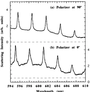
Figure 3 shows the scattering spectra at a scattering angle of 906 5° from the microsphere; these were ob-tained through a polarizer with its polarization axis at 90° (a) and (b) 0° to the SMOF. The MDR’s that are present in Fig. 3(a) are missing when compared with Fig. 3(b), a result that attests to the polarization dependence of the MDR’s. From the polarizer orientation, we can de-duce that the MDR’s that are present in Fig. 3(a) are the transverse-electric (TE) type and that the MDR’s that are present in Fig. 3(b) are the transverse-magnetic (TM) type. Both spectra have been normalized by the laser tensity spectrum, which decreases continually with in-creasing wavelength. To rule out the ellipticity of the mi-croparticle, we also observed the plane-wave scattering spectra (not shown) at a scattering angle of 45° from the microparticle and confirmed that the microparticle was indeed spherical, since the MDR’s corresponding to differ-ent great-circle trajectories occurred at the same wavelength.14
Comparing the spectra shown in Fig. 3 with the scat-tering spectra obtained with a plane wave, we noticed several features: (1) There is a large background inten-sity, which cannot be explained by the light scattering that results from OFC surface imperfections; and (2) The MDR’s have nearly Lorentzian line shapes as opposed to the Fano line shapes15of the plane-wave scattering spec-tra.
3. THEORY OF OFF-AXIS
MORPHOLOGY-DEPENDENT RESONANCE EXCITATION
Most of the prominent features of these scattering spectra are described by the interaction of the microsphere with an external beam having a Gaussian intensity profile and propagating at an impact parameter b, which is slightly greater than the microsphere radius a. Since the excita-tion by such a beam occurs beyond the edge of the micro-sphere, the light scattering can be calculated by (i) re-moval of the partial waves with angular-momentum quantum numbers n less than the size parameter (x 5 2pa/l) from the conventional Lorenz–Mie (plane-wave excitation) infinite series, and (ii) application of GLMT to parameterize the incident-beam profile. This removal of partial waves is justified by the localization principle,16which associates a light ray having an impact parameter b with a partial wave with mode number n. This relationship can be expressed as follows:
b5
S
n 1 1 2D
a
x. (1)
Plane-wave Lorenz–Mie theory restricts the angular-momentum quantum number n range of the light rays, passing by the microsphere surface but yet interacting with it, to be Nx > n > x, where N is the relative refrac-tive index of the microsphere with respect to the outside medium. This condition, together with the localization principle, restricts the impact parameter b range to be Na> b > a. Therefore only the light rays within the impact parameter range of Na> b > a can couple to the MDR’s of the microsphere.
To check the validity of this approach and to simulate our experimental results, we used the GLMT computation algorithm of Ref. 17 (Figs. 4 and 5), which can be applied to on- and off-axis focused Gaussian beam excitation ge-ometries. In GLMT, the plane-wave partial-wave expan-sion coefficients (anfor TM or bn for TE resonances) are
replaced by the partial-wave expansion coefficients (anm
for TM coefficients or bnm for TE coefficients). For
ex-ample, for TE contributions, bnm5 bnBnm, where Bnm5
a2
n~n 1 1!cn~x!
E
0 4pdVHr~V!Ynm*~V!, (2)
with cn(x) being a Ricatti–Bessel function; V, the solid
angle; Hr(V), the radial component of the incident
mag-netic field evaluated on the microsphere surface (r 5 a); and Ynm*(V), a spherical harmonic function. In other
words, Bnmdescribe the angular overlap of the excitation
field and the spherical harmonics.
For our external off-axis Gaussian beam excitation ge-ometry and as seen in Ref. 17, Bnmbecome significant as
Fig. 3. Experimental results obtained with the polarizer at (a) 90° and (b) 0° to the SMOF.
n exceeds x. As n is increased further, Bnmgoes through
a series of resonances (i.e., MDR’s), with none being seen beyond n5 Nx. The background in the spectra of Figs. 4(b) and 5(b) is due to the refraction for nonresonant par-tial waves with n , x. For a plane-wave excitation, Bnmwould have been significant for all n.
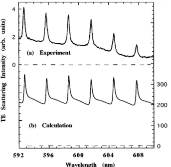
For the calculations [Figs. 4(b) and 5(b)], we used a Gaussian beam (with an infinite skirt length and a beam waist with a half-width v05 2.176 mm) propagating at
an impact parameter of 14.94 mm from a microsphere (with a5 12.34 mm and a relative refractive index of 1.09). The calculation of the scattered intensity is aver-aged over the scattering angle from 906 5°. The results of this calculation [Figs. 4(b) and 5(b)] are compelling. The theoretical MDR’s for an off-axis incidence bear a
good relationship to the experimental data [Figs. 4(a) and 5(a)] and appear to correspond to first-order MDR’s with theoretical quality factors Q’s of approximately 2000. The mode numbers n for the MDR’s are within the range of n 5 194– 198.
By using the localization principle, we can estimate where the beam should have been placed for maximal ex-citation of these MDR’s with n 5 194– 198. We obtain b 5 n/k 5 12.9 mm by using Eq. (1), which is smaller than our experimental value of b 5 14.94mm. Therefore we are not coupling to these MDR’s with n 5 194– 198 with maximal efficiency.
The coupling (scattering) efficiency can be estimated by calculation of the power coupled (scattered) into the partial-wave modes. The power coupled (scattered) into a mode can be calculated by use of the scattering cross section s. The power coupled into a mode can be ex-pressed as the ratio of the partial-wave scattering cross sectionsmodeto the total cross sectionstotalmultiplied by
the incident beam power Pi or, equivalently,smode
multi-plied by the average incident beam intensity ^Ii&. The
power leaking (coupling out) from a mode is proportional to the energy e stored in the mode divided by the time constant t of that mode. Hence the total power going into a mode can be expressed as
de dt 5 smode stotal Pi2 e t 5^smode&Pi2 e t 5 smode^Ii&2 e t, (3) where we have defined^smode& as the scattering (or power
coupling) efficiency into a mode. Then the steady-state energye0in the mode can be expressed as
e05
smode
stotal
Pit 5 ^smode&Pit 5 smode^Ii&t. (4)
For a plane wave, the total cross sectionstotalis 2pa2. A
Gaussian beam with the same intensity as the plane wave, however, has a total cross section of pv02/2.
Therefore an off-axis Gaussian beam will couple more ef-ficiently into a mode if it happens to be propagating at the impact parameter b corresponding to that mode. One can estimate the scattering efficiency for a Gaussian beam (^smode&Gaussian) by following this geometrical point
of view. Figure 6 is a sketch of the transverse view of the Gaussian beam with area pv02 and the cross-sectional
mode area (2pb db). The mode thickness db can be es-timated from the localization principle (bn5 n/k) to be db5 1/k. Only the part of the Gaussian beam that over-laps with the ribbon contributes to the coupling to a spe-cific mode. This area is '
A
2v0db5A
2v0/k5 v0l/
A
2p. We then obtain ^smode&Gaussian'
A
2l/p2v05 0.03 5 3% (for our experimental
param-eters and assuming that our beam was propagating at the appropriate impact parameter). For a plane-wave exci-tation, however, ^smode&plane wave' l/2pa 5 1/x 5 0.005
5 0.5% (for our experimental parameters).
For a better estimate of the power scattered (coupled) into a mode, we can use Lorenz–Mie theory. For a plane-wave illumination, the scattering cross section for a TM-polarized partial wavesanis18
Fig. 4. Scattering intensity of (a) experimental and (b) calcu-lated TE-polarized spectrum.
Fig. 5. Scattering intensity of (a) experimental and (b) calcu-lated TM-polarized spectrum.
san5
2p k2 uanu
2~2n 1 1!, (5a)
where anis the scattered-electric-field coefficient and n is
the angular-momentum quantum (mode) number. Simi-larly, the scattering cross section for a TE-polarized par-tial wavesbnis
sbn5
2p k2 ubnu
2~2n 1 1!, (5b)
where bnis the scattered-electric-field coefficient. Hence
the total scattering cross sectionstotalis
stotal5
(
n51 ` san1sbn 5 2p k2 n(
51 ` ~uanu21 ubnu2! 3 ~2n 1 1! 5 2pa2. (6)For the more general case of an off-axis Gaussian beam illumination, we calculated the scattering cross section for a TM-polarized partial wavesanto be
san5 2p k2 uanu 2
F
2n1 1 2n~n 1 1!G
m(
52n n uAnmu2 ~n 1 umu!! ~n 2 umu!!, (7a) where Anm is the generalized Lorenz–Mie coefficient ofthe scattered electric field and m is the azimuthal quan-tum mode number. Similarly, we have calculated the scattering cross section for a TE-polarized partial wave sbnto be sbn5 2p k2 ubnu2
F
2n1 1 2n~n 1 1!G
m(
52n n uBnmu2 ~n 1 umu!! ~n 2 umu!!, (7b) where Bnm is the generalized Lorenz–Mie coefficient ofthe scattered electric field.
For the more symmetric on-axis Gaussian beam (i.e., with m5 61), the expressions for the TM-polarized partial-wave scattering cross sectionsanreduce to
san5
2p k2 uanu
2~2n 1 1!uA
n61u, (8a)
and the expressions for the TE-polarized partial-wave scattering cross sectionsbn reduce to
sbn5
2p k2 ubnu
2~2n 1 1!uB
n61u. (8b)
All these scattering cross sections (Eqs. 7 and 8) reduce to the plane-wave scattering cross sections [Eqs. (5)], for a plane-wave excitation (withuAn61u5 uBn61u 5 1).
Using Eqs. (7) for an off-axis Gaussian beam illuminat-ing our microsphere, we calculated (Fig. 7) the scatterilluminat-ing efficiency (^sbn&5 2sbn/pv02) for the TE modes as a
function of the impact parameter b and the angular-momentum quantum (mode) number n. Different mode numbers are excited at different impact parameters. For our modes with n 5 194– 198, in accordance with the lo-calization principle, the maximum of the scattering effi-ciency occurs at an impact parameter of 12.9mm. At our impact parameter of 14.94mm, the scattering efficiency is less than 1%. To couple most efficiently (i.e., 1% is a fac-tor of 3 smaller than our geometric estimate of 3%) to our modes with n5 194– 198, we would have had to excite the microsphere at an impact parameter of 12.9mm.
However, efficient coupling is not sufficient for maxi-mum energy storage in the microsphere. As can be seen from Eq. 4, the total energy that can be stored in the mode is proportional to the lifetimet of that mode, which can further be enhanced with the use of a higher refractive-index contrast between the PS microsphere and its surrounding medium, e.g., N 5 1.09 (index-matching liquid)→1.18 (water). Although the water re-sults are more difficult to simulate because of the refractive-index step at the cladding–water interface and because the excitation electric field is evanescent rather than Gaussian, it is possible to have modes with higher measured Q’s of '24,000. Figure 8 shows the experi-mental elastic scattering intensity of the TE-polarized spectrum for a PS microsphere in water (N 5 1.18). These TE resonances are suppressed when the polarizer axis is parallel to the SMOF (not shown). A noteworthy Fig. 6. Transverse view of the ratio of the Gaussian beam area
pv02and the cross-sectional area (2pb db) corresponding to a
mode. The microsphere radius is a.
Fig. 7. Scattering efficiency^sbn& for TE modes for a Gaussian beam illuminating a microsphere with our experimental param-eters plotted as a function of the impact parameter b and the angular-momentum quantum (mode) number n.
feature of the spectra shown in Fig. 8 is that MDR’s with linewidths as narrow as 0.04 nm were observed. Since our dye laser has a linewidth of 0.025 nm, the measured MDR linewidths are clearly limited by the convolution of our dye laser linewidth.
4. CONCLUSION
In conclusion, the microsphere–optical fiber system with the index-matching geometry has proved to be very useful in the verification of the generalized Lorenz–Mie theory and the localization principle. The microsphere–optical fiber system also shows promise as a possible building block for photonic memories19 and can be used as an external-cavity feedback system to line narrow a broader light source such as a diode laser.20,21
ACKNOWLEDGMENTS
We are grateful for research support from the U.S. Air Force Office of Scientific Research (grant F49620-94-0195) and the Scientific and Technical Research Council of Turkey (TUBITAK grant TBAG-1368).
REFERENCES
1. P. W. Barber and R. K. Chang, eds., Optical Effects Associ-ated with Small Particles (World Scientific, Singapore, 1988), pp. 3–61.
2. E. M. Purcell, ‘‘Spontaneous emission probabilities at radio frequencies,’’ Phys. Rev. 69, 681 (1946).
3. S. C. Ching, H. M. Lai, and K. Young, ‘‘Dielectric micro-spheres as optical cavities: thermal spectrum and density of states,’’ J. Opt. Soc. Am. B 4, 1995 (1987).
4. S. C. Ching, H. M. Lai, and K. Young, ‘‘Dielectric micro-spheres as optical cavities: Einstein A and B coefficients and level shift,’’ J. Opt. Soc. Am. B 4, 2004 (1987). 5. D. S. Benincasa, P. W. Barber, J.-Z. Zhang, W.-F. Hsieh,
and R. K. Chang, ‘‘Spatial distribution of the internal and near-field intensities of large cylindrical and spherical scat-terers,’’ Appl. Opt. 26, 1348 (1987).
6. E. E. M. Khaled, S. C. Hill, and P. W. Barber, ‘‘Internal electric energy in a spherical particle illuminated with a plane wave or off-axis Gaussian beam,’’ Appl. Opt. 33, 524 (1994).
7. J.-Z. Zhang, D. H. Leach, and R. K. Chang, ‘‘Photon lifetime
within a droplet: temporal determination of elastic and stimulated Raman scattering,’’ Opt. Lett. 13, 270 (1988). 8. J. P. Barton, D. R. Alexander, and S. A. Schaub, ‘‘Internal
and near-surface electromagnetic fields for a spherical par-ticle irradiated by a focused laser beam,’’ J. Appl. Phys. 64, 1632 (1988).
9. J. A. Lock and G. Gouesbet, ‘‘Rigorous justification of the lo-calized approximation to the beam shape coefficients in generalized Lorenz–Mie theory. I. On-axis beams,’’ J. Opt. Soc. Am. A 11, 2503 (1994).
10. G. Gouesbet and J. A. Lock, ‘‘Rigorous justification of the lo-calized approximation to the beam shape coefficients in generalized Lorenz–Mie theory. II. Off-axis beams,’’ J. Opt. Soc. Am. A 11, 2516 (1994).
11. A. Serpengu¨ zel, S. Arnold, and G. Griffel, ‘‘Excitation of resonances of microspheres on an optical fiber,’’ Opt. Lett.
20, 654 (1995).
12. N. Dubreuil, J. C. Knight, D. K. Leventhal, V. Sandoghar, J. Hare, and V. Lefe`vre, ‘‘Eroded monomode optical fiber for whispering-gallery mode excitation in fused-silica micro-spheres,’’ Opt. Lett. 20, 813 (1995).
13. S. Arnold, S. Holler, J. H. Li, A. Serpengu¨ zel, W. F. Auffer-mann, and S. C. Hill, ‘‘Aerosol particle microphotography and glare spot absorption spectroscopy,’’ Opt. Lett. 20, 773 (1995).
14. G. Chen, Md. M. Mazumder, Y. R. Chemla, A. Serpengu¨ zel, R. K. Chang, and S. C. Hill, ‘‘Wavelength variation of laser emission along the entire rim of slightly deformed micro-droplets,’’ Opt. Lett. 18, 1993 (1993).
15. P. W. Barber and R. K. Chang, eds., Optical Effects Associ-ated with Small Particles (World Scientific, Singapore, 1988), p. 20.
16. H. C. van de Hulst, Light Scattering by Small Particles (Do-ver, New York, 1981), p. 208.
17. J. A. Lock, ‘‘An improved Gaussian beam scattering algo-rithm,’’ Appl. Opt. 34, 559 (1995).
18. C. F. Bohren and D. R. Huffman, Absorption and Scattering of Light by Small Particles (Wiley, New York, 1983), p. 103. 19. S. Arnold, C. T. Liu, W. B. Whitten, and J. M. Ramsey, ‘‘Room-temperature microparticle-based persistent spectral hole burning memory,’’ Opt. Lett. 16, 420 (1991).
20. G. Griffel, A. Serpengu¨ zel, and S. Arnold, ‘‘Quenching of semiconductor lasers linewidth by detuned loading using spherical cavities morphology dependent resonances,’’ in Proceedings of IEEE Frequency Control Conference (Insti-tute of Electrical and Electronics Engineers, New York, 1995), pp. 495–497.
21. G. Griffel, S. Arnold, D. Taskent, A. Serpengu¨ zel, J. Con-nolly, and N. Morris, ‘‘Morphology-dependent resonances of a microsphere–optical fiber system,’’ Opt. Lett. 21, 695 (1996).