Beam steering in a Half-Frequency driven Airborne
CMUT transmitter array
Talha Masood Khan
UNAM-National Nanotechnology Research Center, Institute of Material Science and
Nanotechnology, Bilkent University Ankara, Turkey
A. Sinan Tasdelen
Bilkent University Acoustics and Underwater Technologies Research Center, Bilkent
University Ankara, Turkey [email protected]
Mehmet Yilmaz
UNAM-National Nanotechnology Research Center, Institute of Material Science and
Nanotechnology, Bilkent University Ankara, Turkey
Abdullah Atalar
UNAM-National Nanotechnology Research Center, Bilkent University Acoustics and Underwater Technologies Research Center &
Electrical and Electronics Engineering Department, Bilkent University,
Ankara, Turkey [email protected]
Hayrettin Koymen
UNAM-National Nanotechnology Research Center, Bilkent University Acoustics and Underwater Technologies Research Center &
Electrical and Electronics Engineering Department, Bilkent University,
Ankara, Turkey [email protected]
Abstract—An airborne Capacitive Micromachined Ultrasonic Transducer (CMUT) transmit array was designed using electro-mechanical modelling for unbiased airborne operation. The array elements are designed for maximum swing at 10V p-p unbiased drive, whereas conventional practice is to bias CMUT close to the collapsed voltage to achieve higher swing. The devices were fabricated using a customized single photolithographic process with a combination of wet and dry etching. The wafer level fabrication enabled the usage of 2x2 and 3x3 arrays. Driving CMUTs in an unbiased mode at half frequency drives the ‘static pressure’ depressed silicon membrane at a larger swing without letting it collapse. The 2x2 array displays 3.375 kHz bandwidth when characterized in air. The phase and amplitude differences due to the dispersion of resonance frequencies of the elements are compensated for beamformed and beamsteered airborne operation.
Keywords—CMUT, airborne, beamforming, microfabrication, un-collapsed
I. INTRODUCTION
CMUTs have been produced for over several decades for both Airborne and Waterborne applications [1-3]. Although they provide excellent performance in waterborne applications, an efficient airborne CMUT ‘array’ has not been described in literature yet. Performance of many airborne ultrasound applications have been limited by narrow Bandwidth (BW). Here, a CMUT offers a wider BW in air, in comparison to alternative piezoelectric options.
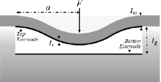
Figure 1 shows a cross-sectional view of a single element of a CMUT. Here a is the radius of the CMUT, tge is effective gap
height, ti is thickness of insulator (Al2O3), tm is membrane
thickness and tg is the gap between top and bottom electrode. F
is the overall force being exerted on the membrane. An acoustic wave is produced by application of electrical signal between top and bottom electrodes of CMUT [4].
Fig. 1. Cross section of a single CMUT element. The flexed membrane is made of 40µm Si, and 100nm of Al2O3
II. DESIGNING AND MODELLING
In principle CMUT operates at a fixed DC bias generating a strong deflecting force on the membrane. Earlier works [5] show that operating a CMUT in an unbiased mode (half frequency) enables a full swing in the gap without collapsing. Using an accurate equivalent circuit model based characterization, a performance analysis is achieved. [3].
The capacitance, δC(r; t), of a concentric narrow ring on the plate of radius r and width dr can be expressed as
𝛿𝐶(𝑟; 𝑡) = 𝜀𝑜2𝜋𝑟𝑑𝑟
𝑡𝑔𝑒−𝑥(𝑟,𝑡)=
𝜀𝑜2𝜋𝑟𝑑𝑟 𝑡𝑔𝑒−𝑥𝑝(𝑡)(1−𝑟2𝑎2)2
(1) Where ε0 is permittivity of the gap, and tge is the effective
gap (tg+ti/εr).
For transmitting CMUT elements, Large Signal Equivalent model was used (Figure 2). CRm and LRm are the compliance of
the plate and the inductance corresponding to the mass of the plate suitable for the {fR, vR} rms model. ZRR is the radiation
resistance of the element. The left hand side of the figure shows the electrical end of the circuit model, while left hand side the mechanical side.
2019 IEEE International Ultrasonics Symposium (IUS) Glasgow, Scotland, October 6-9, 2019
Device parameters of tm=40um, ti=100nm, εr=9.5
(Alumina), were used to derive radius a using the following equation. [6] 𝑓𝑟= 𝑡𝑚 𝑎2 1 2𝜋√ 80𝑌0 9𝜌𝑚(1−𝜎2)= 3805 𝑡𝑚 𝑎2 (2)
For a fr=77kHz, tm/a2 is 20.24, which in turns makes
a=1.4mm. Hence to limit peak deflection of large ka of 2, tg/tm=0.25 was used (k is wave number). A tg of 10um was
extracted through simulation for this purpose (This enables the plate to operate in linear elastic regime). For these parameters,
Fb/Fg=0.673 was derived, which was enough to produce 6µm of
peak deflection. For an un-collapsed airborne CMUT transmitter simulation, the material parameter in table 1 were used. For an array, spacing d of 3mm was selected to comply with material geometry (Figure 3). An Advanced Design System (ADS) simulation of this cell produced a Q factor of 206 (Figure 4).
III. FABRICATION
After the design process, a photomask containing various arrays and array types was designed. The fabrication of CMUT arrays was divided into two parts, 420µm thick SOI and 500µm thick Pyrex wafer. The SOI wafer was first cleaned using a RCA method followed by Piranha cleaning. 100nm of Aluminum oxide (Al2O3) was deposited on device side of SOI wafer using
a thermal Atomic Layer Deposition (ALD) process.
The Pyrex wafer was processed by initiating with a single photolithographic process followed by wet etching 10um trenches into Pyrex wafer and further coated with a Metal stack (100nm Ti/ 100nm Pt/ 50nm Au) (Figure 5). Once both of the wafers were processed, they were anodically bonded (Figure 6). Following this, the Handle layer was plasma etched using a specialized, isotropic, Reactive Ion Etch (RIE) process in an Inductively Coupled Plasma (ICP) chamber. Removal of the handle layer revealed the buried oxide layer over the Device layer, which was carefully removed using a wet Buffer Oxide Etch (BOE) etchant.
The devices were sealed using a sealing epoxy and the cavities underneath them were vacuumed. A PCB was designed to take out connections from the wafer to be soldered onto the electronics.
IV. CHARECTERIZATION AND TESTING A. Impedance Measurements
An impedance analyzer (HP 4194A) was used to measure the impedance characteristics of the CMUT arrays. The measurements were carried out in two modes, which are, array mode (all elements connected as shown in Figure 7) and element mode (single element biased while the others are grounded). For a CMUT array, measured and simulated results were correlated. A modified large circuit equivalent model was used to include the losses into the simulations. Figure 8 shows a fitted and measured conductance characteristic of a 3x3 array. The resonant frequency was shifted to 75 kHz owing to change in material parameters.
TABLE I. MATERIAL PARAMTERS FOR SIMULATION
Parameters Si Air
Young’s Modulus 148GPa
Poisons Ratio 0.17
Density (kg/m3) 2370 1.27
Speed of Sound (m/s) 331
Fig. 2. Large signal Equivalent model for designing a CMUT transmitter. Left hand side depicts the electrical while the right hand side shows mechanical side.
Fig. 3. A 2x2 array with a pitch (d) of 3mm
Fig. 4. Conducatance performance of a 2x2 array under bias of -20V to +20V 2019 IEEE IUS
Glasgow, Scotland, October 6-9, 2019
Fig. 5. An unbonded pyrex wafer with CMUT arrays on top
Fig. 6. Crossection of Bonded Pyrex (bottom) and SOI wafer (Top)
Fig. 7. Measurement configuration for Impedacne charecterization of a 2x2 array.
Fig. 8. Measured and fitted conductance values for a 3x3 CMUT array
B. Pressure Measurements
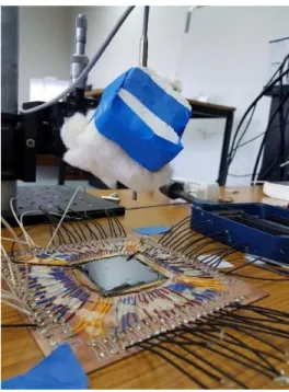
An NI-DAQ card PXI 6733 was used to drive a 2x2 array at no bias (Half Frequency). A setup was devised to measure the radiated pressure using a BK-4138 microphone at varying height and angles (Figure 9). An A.C. signal of 10Vp-p was used to
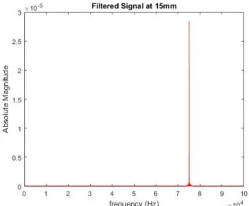
excite the element at 38 kHz. Microphone placed at 15mm height has a preamplifier that converts acoustic pressure into amplitude change. This received in real time on a Lab-View interface (Figure 10).
After fabrication cycle, variations in physical characteristics, such as membrane thickness or slight variation in diameter of CMUT was observed. These variations, if not accounted for properly, may result in unwanted effects, such as variations in resonant frequency, and phase difference between each element of an array. The design frequency 77 kHz was shifted to 75 kHz after fabrication (Figure 8). As the elements of array were wet and dry etched, there was a slight variation in the membrane thickness and vacuum inside the cavities. This resulted in a difference in pressure radiated by CMUT elements. To compensate, each element was driven separately at 10Vp-p and a
resulting pressure was noted. The input voltage for element producing high pressures (up to 200mPa) were reduced to 7Vp-p
to equalize the sound pressure emitted by each element (Bringing it down to 150mPa). For phase difference compensation in each element, a lock-in Amplifier (SR830) with a set time constant of 100µs and a filter roll off of 12dB/octave was used. Each element in an array were driven using a single source and output signal from the microphone was connected as a reference to the lock-in Amplifier. The difference in phase detected was later added to each individual input to compensate for the inherent phase difference in each element. A phase compensation of 0.27π, 0.46π, 0.5π and 0.7π to each individual element of a 2x2 CMUT array resulted in the beam to be formed as shown in Figure 11 and Figure 12.
Fig. 9. The acoustic signal acquiring setup. The microphone hangs on an XYZ table that measures the pressure on varying angles.
2019 IEEE IUS
Glasgow, Scotland, October 6-9, 2019
Fig. 10. An FFT (Fast Fourier Transform) of a time domain amplitude signal received from exciting a single CMUT element onto a microphone 15mm away.
Fig. 11. Received pressure of a 2x2 array at 20mm height from the array
Fig. 12. Normallized acoustic pressures measured and simulted at varying angles over the CMUT array.
V. CONCLUSION
Airborne CMUTs have a narrow bandwidth. The minor differences in the resonance frequencies of the cells in the array must be compensated for beam forming. The measured bandwidth of 3.375 kHz was higher than expected BW owing to various factors, including the loss of energy propagating to the surface and substrate. A pressure of 150mPa was measured when the array elements were driven in parallel with 10V peak-to-peak voltage, 20mm away from the source. The arrays can be used to steer beam onto a specific angle if the appropriate compensation is added.
REFERENCES
[1] A Unlugedik, A. Atalar, and H. Koymen, "Designing an effecient wide bandwidth single cell CMUT for airbore applications using nonlinear effects," in Proc. lEEE Ultrasonics Symp., 2013, pp.1416-1419.
[2] S. Olcum et al, “Wafer bonded capacitive micromachined underwater transducers”, in Proc. lEEE Ultrasonics Symp., 2009, pp.976-977.
[3] H. Koymen, et a!., "An improved lumped element nonlinear circuit model for a circular CMUT cell," IEEE Trans. on Ultrason., Ferroelec. and Freq. Cont., vol. 59, no. 8, pp. 1791-1799, August 2012
[4] A. Unlugedik, et al., "Designing Efficient CMUT Cells for Airborne Applications," in Proc. lEEE Ultrasonics Symp., 2014, pp.2564-2567.
[5] A. Unlugedik, et al., "Designing transmitting CMUT cells for airbore applications," IEE Trans. on Ultrason., Ferroelec. and Freq. Cont.,vol 61 , Issue: 11, pp. 1899-1910, November 2014,
[6] S. Timoshenko, S. Woinowsky-Krieger, and S. Woinowsky, ‘Theory of plates and shells’, vol. 2. McGraw-hill New York, 1959.
2019 IEEE IUS
Glasgow, Scotland, October 6-9, 2019