Waveform Design for 5G and Beyond
Ali Fatih Demir
1, Mohamed Elkourdi
1, Mostafa Ibrahim
2, Huseyin Arslan
1,2 1University of South Florida, Department of Electrical Engineering, Tampa, FL, USA
2
Istanbul Medipol University, Department of Electrical and Electronics Engineering, Istanbul, Turkey
I. INTRODUCTION
The standardization activities of wireless mobile telecommunications have begun with analog standards that were introduced in the 1980s, and a new generation develops almost every 10 years to meet the exponentially growing market demand. The leap from analog to digital started in second-generation (2G) systems, along with the use of mobile data services. The 3G digital evolution enabled video calls and global positioning system (GPS) services on mobile devices. The 4G systems pushed the limits of data services further by better exploiting the time–frequency resources using orthogonal frequency-division multiple access (OFDMA) as an air interface [1]. Recently, the International Telecommunications Union (ITU) has defined the expectations for 5G [2], and the study of the next-generation wireless system is in progress with a harmony between academia, industry, and standardization entities to accomplish its first deployment in 2020.
5G is envisioned to improve major key performance indicators (KPIs), such as peak data rate, spectral efficiency, power consumption, complexity, connection density, latency, and mobility, significantly. Furthermore, the new standard should support a diverse range of services all under the same network [3]. The IMT-2020 vision defines the use cases into three main categories as enhanced mobile broadband (eMBB), massive machine-type communications (mMTC), and ultra-reliable low-latency communications (URLLC) featuring 20 Gb/s peak data rate, 106/km2device density, and less than 1 ms latency, respectively [4]. A flexible air interface is required to meet these different requirements. As a result, the waveform, which is the main component of any air interface, has to be designed precisely to facilitate such flexibility [5].
This chapter aims to provide a complete picture of the ongoing 5G waveform discussions and overviews the major candidates. The chapter is organized as follows: Section II provides a brief description of the waveform and reveals the 5G use cases and waveform design requirements. Also, this section presents the main features of CP-OFDM that is currently deployed in 4G LTE systems. CP-OFDM is the baseline of the 5G waveform discussions since the performance of a new waveform is usually compared with it. Section III examines the essential characteristics of the major waveform candidates along with the related advantages and disadvantages. Section IV summarizes and compares the key features of the waveforms. Finally, Section V concludes the chapter.
Time–frequency plane
…
Where to transmit: Lattice
How to transmit: Pulse shaping filter
Time
What to transmit: Symbols
Symbol spacings
n-1 n n+1
Figure 1: Waveform definition [6].
II. FUNDAMENTALS OF THE5G WAVEFORMDESIGN
A. Waveform Definition
The waveform defines the physical shape of the signal that carries the modulated information through a channel. The information is mapped from the message space to the signal space at the transmitter, and a reverse operation is performed at the receiver to recover the message in a communications system. The waveform, which defines the structure and shape of the information in the signal space, can be described by its fundamental elements: symbol, pulse shape, and lattice, as shown in Fig 1. The symbols constitute the random part of a waveform whereas the pulse shape and the lattice form the deterministic part.
• Symbol:A symbol is a set of complex numbers in the message space that is generated by grouping a number of bits together. The number of bits grouped within one symbol determines the modulation order that has a high impact on the throughput.
• Pulse Shape: The form of the symbols in the signal plane is defined by the pulse shaping filters. The shape of the filters determines how the energy is spread over the time and frequency domains and has an important effect on the signal characteristics.
• Lattice:The lattice is generated by sampling the time–frequency plane, and the locations of samples define the coordinates of the filters in the time–frequency grid. The lattice geometry might present different shapes such as rectangular and hexagonal according to the formation and distances between the samples. Furthermore, the lattice can be exploited by including additional dimensions such as space domain.
B. 5G Use Cases and Waveform Design Requirements
The new radio for 5G should support a wide range of services as discussed in Section I. Primarily, the applications that require larger bandwidth and spectral efficiency falls into eMBB category, whereas the ones that have a tight requirement for device battery life falls into mMTC. Usually, the industrial smart sensors [7] or medical implants [8] operate several years without the demand for maintenance and hence low device complexity and high energy
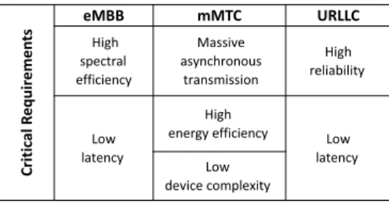
efficiency are crucial for these mMTC services. Furthermore, the mission-critical applications such as remote surgery [9] or self-driving vehicles [10] are represented in URLLC. The key requirements that are associated with each of these use cases are summarized in Table I and the following design criteria are essential to meet these requirements of 5G:
• High Spectral Efficiency:The modulation order, type of pulse shaping filters, and density of the lattice play an important role in determining the spectral efficiency. The guard units in time or frequency domains and other extra overheads decrease the spectral efficiency, which is critical especially for the eMBB type of communications. Furthermore, the multi-antenna techniques [11] such as beamforming and massive MIMO is another crucial aspect to utilize the lattice more efficiently. However, the self-ISI and self-ICI of a waveform prevents to apply MIMO techniques in a straight-forward way and increases complexity significantly. • Low Latency: 5G targets a latency less than 1 ms for the URLLC applications. This goal can be managed
by shortening the transmission time interval (TTI) or increasing the sub-carrier spacing. However, the latter approach increases the relative CP overhead for a given TTI. Also, the localization in time is critical, and shorter filter/window durations are needed to fulfill this requirement.
• High Reliability: The reliability is evaluated by bit error rate (BER) or block error rate (BLER), and it is extremely important for mission-critical communications where errors are less tolerable. In addition, the re-transmissions due to errors cause an increase in latency, and hence high reliable links are desirable to provide low latency as well.
• Massive Asynchronous Transmission:It is envisioned that there will be a huge number of nodes communicating over the 5G network for mMTC services. To maintain the synchronicity, excessive overhead is required for these applications. However, it decreases the spectral efficiency significantly. The waveforms that have strict synchronization requirements to achieve interference-free communications are not suitable for mMTC applications. Therefore, the waveforms that are well localized in the multiplexing domain are more suitable to relax the synchronization requirement for these type of applications.
• Low Device Complexity:The computational complexity is another critical metric of the waveform design and depends on the number of operations required at the transmitter or receiver. Additional windowing, filtering, and interference cancellation algorithms increase complexity substantially, and the system designer should consider it to design a cost- and energy-efficient transceivers.
Table I: The 5G use cases
Cr iti ca l R eq ui re m en
ts eMBBHigh mMTC URLLC
spectral efficiency Massive asynchronous transmission High reliability Low latency High
energy efficiency Low latency Low
• High Energy Efficiency:Low computational complexity and low peak-to-average power ratio (PAPR) provides high energy efficiency. PAPR is a statistical metric that is evaluated by complementary cumulative distributive function (CCDF) of the signal. Low PAPR is required to operate power amplifiers (PAs) efficiently, which are one of the most energy-hungry components in a transceiver.
C. The Baseline for 5G Waveform Discussion: CP-OFDM
Orthogonal frequency-division multiplexing (OFDM) is the most popular multicarrier modulation scheme that is currently being deployed in many standards such as the downlink of 4G LTE and the IEEE 802.11 family [12]. Its primary advantage over the single-carrier transmission schemes is its ability to cope with frequency selective channels for broadband communications. The data is divided into parallel streams, and each is modulated with a set of narrow subcarriers. The bandwidth of each subcarrier is set to be less than the coherence bandwidth of the channel. Hence, each subcarrier experiences a single-tap flat fading channel that can be equalized in the frequency domain with a simple multiplication operation. Also, OFDM systems utilize the spectrum in a very efficient manner due to the orthogonally overlapped subcarriers and allow flexible frequency assigning. A discrete OFDM signal on baseband is expressed as follows:
sOF DM[k] = N −1 X n=0 dnej2πk n N (1)
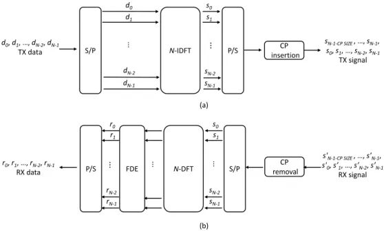
where dnis the complex data symbol at subcarrier n, and N represents the total number of subcarriers. OFDM can easily be implemented by the inverse fast Fourier transform (IFFT) algorithm. Afterward, the cyclic prefix (CP) is added by copying the last part of the IFFT sequence and appending it to the beginning as a guard interval. The CP length is determined based on the maximum excess delay of the channel to alleviate the effect of inter symbol interference (ISI). However, it is hard-coded in 4G LTE and does not take into account the individual user’s channel delay spread. As a result, the fixed guard interval leads to a degradation in the spectral efficiency. Furthermore, the CP yields to handling the interference in a multipath environment by ensuring circularity of the channel and by enabling easy frequency-domain equalization (FDE). OFDM partly diminishes the inter carrier interference (ICI) as well by setting the subcarrier spacing according to the maximum Doppler spread. A block diagram of conventional CP-OFDM transmitter and receiver is shown in Fig. 2.
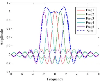
A major disadvantage of any multicarrier system, including CP-OFDM, is high peak-to-average power ratio (PAPR) due to the random addition of subcarriers in the time domain. For instance, consider the four sinusoidal signals as shown in Fig. 3 with different frequencies and phase shifts [13]. The resulting signal envelope presents high peaks when the peak amplitudes of the different signals are aligned at the same time. As a result of such high peaks, the power amplifier at the transmitter operates in the nonlinear region causing a distortion and spectral spreading. In addition, as the number of subcarriers increases, the variance of the output power increases as well. Another critical issue related to the CP-OFDM systems is its high out of band emissions (OOBE). The OFDM signal is well localized in the time domain with a rectangular pulse shape that results in a sinc shape in the frequency domain as shown in Fig. 4. Especially, the sidelobes of the sincs at the edge carriers cause significant
(a) d0, d1, …, dN-2, dN-1
TX data S/P N-IDFT P/S insertionCP
d0 d1 dN-2 dN-1 s0 s1 sN-2 sN-1 sN-1-CP SIZE , …, sN-1, s0, s1, …, sN-2, sN-1 TX signal CP removal s'N-1-CP SIZE , …, s’N-1, s'0, s’1, …, s’N-2, s’N-1 RX signal (b) S/P N-DFT FDE r0, r1, …, rN-2, rN-1 RX data P/S s0 s1 sN-2 sN-1 r0 r1 rN-2 rN-1 ⋮ ⋮ ⋮ ⋮ ⋮
Figure 2: CP-OFDM block diagram. (a) Transmitter. (b) Receiver.
interference and should be reduced to avoid adjacent channel interference (ACI). Typically, OOBE is reduced by various windowing/filtering approaches along with the guard band allocation [14] to meet the spectral mask requirements of the various standards. 3GPP LTE standard uses 10% of total bandwidth as guard bands to handle this problem. However, fixed guard allocation decreases the spectral efficiency.
Furthermore, OFDM systems are more sensitive to synchronization errors than single-carrier systems. As an example, if the orthogonality is lost due to the frequency offset, Doppler spread, or phase noise, the leakage from other subcarriers causes ICI. Similarly, the timing offset causes ISI or ICI when it occurs outside the guard interval. Numerous waveforms are proposed considering all these disadvantages for the upcoming 5G standard [4], [15]– [18]. Although backward compatibility, low implementation complexity, and easy multiple-input multiple output (MIMO) integration still make CP-OFDM an important candidate for the new standards, it seriously suffers from
High peak
Frequency A m p li tu d e Freq1 Freq2 Freq3 Freq4 Freq5 Sum
Figure 4: The OOBE problem in multicarrier schemes.
its limited flexibility and the unfriendly coexistence with different numerologies for various channel conditions and use cases in addition to the aforementioned problems. The proposed waveforms provide better flexibility and time–frequency localization using various filtering/windowing approaches and precoding strategies with certain trade-offs. Also, the external guard interval, that is CP, is suggested to be replaced with flexible internal guard interval to improve spectral efficiency further and to provide better performance. However, it is only being considered for the single-carrier schemes for practical reasons currently. The major waveform candidates for 5G and beyond are classified, as shown in Fig. 5, and discussed thoroughly in the following sections.
III. MAJORWAVEFORMCANDIDATES FOR5GANDBEYOND
A. Multicarrier Schemes
1) Windowing: The discontinuity between adjacent symbols due to the rectangular window shape in the time domain causes high OOBE for CP-OFDM. Windowed-OFDM (W-OFDM) [15] smooths these sharp edges in a straightforward way with low complexity. The baseband W-OFDM can be expressed as follows:
WAVEFORM CLASSIFICATION TREE
Multicarrier schemes Windowed • W-OFDM Subcarrier wise filtered • FBMC • GFDM Subband wise filtered • UFMC • F-OFDM Single-carrier schemes External guard interval • CP-DFT-s-OFDM Internal guard interval • ZT-DFT-s-OFDM • UW-DFT-s-OFDM
TOFDM
TCP
CP for channel CP for windowing
Postfix for windowing
Overlap with next symbol
Figure 6: W-OFDM (Transmitter).
sW −OF DM[k] = +∞ X m=−∞ N −1 X n=0 dm,ng[k − m(N + LCP + LExt)]ej2πk n N (2)
where dm,nis the complex data transmitted on the nthsubcarrier and mthOFDM symbol, LCPpresents the CP length, LExtexpresses the windowing extension, and g[n] shows the windowing function. Several windowing functions have been evaluated in detail [19] with different trade-offs between the width of the main lobe and suppression of the side lobes. An illustration of windowing operation at the transmitter is shown in Fig. 6.
Initially, the CP is further extended on both edges at the transmitter and the extended part from the beginning of the OFDM symbol is appended to the end. The windowing operation is applied symmetrically on both edges of the OFDM symbol, and the transitions parts (i.e., ramp-ups and ramp-downs) of adjacent symbols are overlapped to shorten the extra time domain overhead resulting from windowing. In addition, the windowing operation is performed at the receiver as well to reduce the interference from other users.
Edge windowing [20] is another approach to reduce the high OOBE of CP-OFDM. It is well known that the outer subcarriers have a higher influence on OOBE problem compared to the inner subcarriers. However, conventional windowing techniques apply the same window for all subcarriers within an OFDM symbol. As a result, the spectral efficiency decreases due to an extra windowing duration or the performance degrades since the effective CP length of channel shortens. The proposed approach borrows the CP duration of the channel to perform windowing and maintains the spectral efficiency (Fig. 7). The longer windows that decrease the effective CP size are applied only to the edge subcarriers, as shown in Fig. 8 and hence the OOBE is suppressed with a minimal performance loss. If the CP of the edge subcarriers is less than or equal to the maximum excess delay of the channel, neither ISI
Edge CP Edge
window windowInner
IFFT O/P Inner CP Time Edge windowing
IFFT (subcarrier from 1 to L) IFFT (subcarrier from L+1 to I) IFFT (subcarrier from I+1 to N) CP insertion and postfix CP insertion and postfix CP insertion and postfix P/S P/S P/S Left window function Inner window function Right window function IFFT IFFT IFFT IFFT IFFT CP postfix Data symbol vector Effective CP Effective CP Effective CP A B C d1 ⋮ dL dL+1 ⋮ dI dI+1 ⋮ dN (a) A B C IFFT ⋮ ⋮ ⋮ 0 0 𝑑1 ⋮ 𝑑𝐿 0 ⋮ 0 0 0 0 IFFT ⋮ ⋮ ⋮ 0 0 0 ⋮ 0 𝑑𝐿+1 ⋮ 𝑑𝐼 0 ⋮ 0 IFFT ⋮ ⋮ ⋮ 0 0 0 ⋮ 0 0 0 0 𝑑𝐼+1 ⋮ 𝑑𝑁 ⋮ ⋮ ⋮ ⋮ ⋮ (b)
Figure 8: Edge windowing block diagram [21].
nor ICI is observed. Therefore, these edge subcarriers should be assigned to the user equipments that experience shorter delay spread. The edge windowed OFDM provide a better spectrum confinement with a low complexity and negligible performance loss [21].
Although windowing approaches present lower OOBE compared to CP-OFDM, the effect is limited and nonneg-ligible guard bands are still required. However, these methods can be applied along with the filtering approaches that are discussed in the following sections to provide better spectral confinement.
2) Subcarrier-Wise Filtering:
a) FBMC
Filter bank multicarrier (FBMC) yields a good frequency-domain localization by extending the pulse duration in the time domain and using properly designed pulse shaping filters [6], [19]. These flexible filters are applied at the subcarrier level, and they enable adaption to various channel conditions and use cases. There are various ways to implement FBMC such as filtered multitone (FMT), cosine modulated multitone (CMT), and staggered modulated multitone (SMT). However, SMT, which is widely known as offset quadrature amplitude modulation OQAM–FBMC, is the focus of 5G waveform discussion due to its ability to handle interference while allowing dense symbol placement in the time–frequency lattice [4]. OQAM signaling provides staggering of “in-phase” and
T Δf T Δf QAM OQAM In-phase Quadrature-phase
Figure 9: QAM signaling versus OQAM signaling [22].
“quadrature-phase” components in both time and frequency domains, as shown in Fig. 9 and hence, orthogonality is maintained within the real and imaginary domains separately.
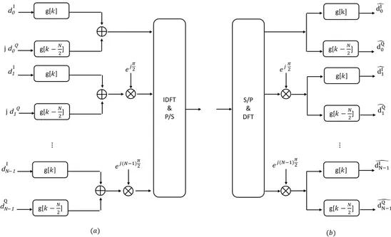
The baseband FBMC/OQAM is expressed as follows:
sF BM C−OQAM[k] = +∞ X m=−∞ N −1 X n=0 dm,ng[k − m N 2]e j2πkn Nejφm,n (3)
where g represents the prototype filter, φm,nis an additional phase term at subcarrier n and symbol index m, which
IDFT & P/S g[𝑘𝑘] g[𝑘𝑘 −𝑁𝑁 2] g[𝑘𝑘] g[𝑘𝑘 −𝑁𝑁 2] 𝑒𝑒𝑗𝑗(𝑁𝑁−1)𝜋𝜋2 g[𝑘𝑘] g[𝑘𝑘 −𝑁𝑁2] 𝑒𝑒𝑗𝑗𝜋𝜋2 d0I j d0Q d1I j d1Q dN−1I j dN−1 Q (𝑎𝑎) S/P & DFT 𝑒𝑒𝑗𝑗(𝑁𝑁−1)𝜋𝜋2 𝑒𝑒𝑗𝑗 𝜋𝜋2 g[k] g[𝑘𝑘 −𝑁𝑁2] g[𝑘𝑘] g[𝑘𝑘 −𝑁𝑁 2] g[𝑘𝑘] g[𝑘𝑘 −𝑁𝑁2] � d0I � d0Q � d1I � d1Q � dN−1I � dN−1Q (𝑏𝑏) ⋮ ⋮
is expressed as π2(m + n). The dm,n is real valued since the real and imaginary parts are transmitted with a delay. Also, to address a perfect reconstruction of symbols, the prototype filter must satisfy the orthogonality condition [17]. A block diagram of conventional OQAM–FBMC transmitter and receiver is shown in Fig. 10.
The subcarriers are well localized in the frequency domain due to the utilization of prototype filters and are spread over only a few subcarriers in FBMC systems. Furthermore, the orthogonality between neighbor subcarriers is ensured using OQAM. As a result, the equalization is simplified without the use of CP, and no more than one subcarrier is required as a guard band for non-orthogonal transmissions [4]. The savings on both guard band and guard duration enable this waveform to achieve better spectrum efficiency compared to CP-OFDM. Also, the well-localized subcarriers in OQAM–FBMC make it suitable for high mobility applications as it is more immune to the Doppler effects. On the other hand, there exist several practical challenges currently. The MIMO integration and pilot design with OQAM–FBMC are not straightforward as in CP-OFDM due to the intrinsic interference resulting from OQAM signaling [23].
b) GFDM
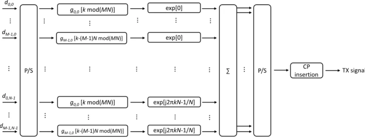
Generalized frequency division multiplexing (GFDM) [24] also applies subcarrier filtering similar to FBMC. However, the filters for pulse shaping are circularly convoluted over a defined number of symbols. Also, the symbols are processed blockwise, and CP is appended to this block. Considering N subcarriers in each subsymbol group and M subsymbol group in each block, a GFDM symbol is represented as follows:
sGF DM[k] = M −1 X m=0 N −1 X n=0 dm,ngm,n[(k − mN )mod(M N )]ej2πk n N (4)
where dm,nis the complex data transmitted on the nthsubcarrier and mth sub symbol, and g[n] shows the prototype filter. Although FBMC prototype filters must satisfy orthogonality condition, there is no constraint on GFDM prototype filters [17]. Hence, GFDM is usually a nonorthogonal transmission scheme with nonorthogonal filters. A block diagram of conventional GFDM transmitter is shown in Fig. 11.GFDM-1
∑ P/S TX signal g0,0 [k mod(MN)] CP insertion exp[0] P/S d0,0 dM-1,0 d0,N-1 dM-1,N-1 gM-1,0 [k-(M-1)N mod(MN)] exp[0] ⋮ exp[j2πkN-1/N] exp[j2πkN-1/N] g0,0 [k mod(MN)] gM-1,0 [k-(M-1)N mod(MN)] ⋮ ⋮ ⋮ ⋮ ⋮ ⋮ ⋮ ⋮ ⋮ ⋮ ⋮ ⋮ ⋮ ⋮ ⋮ ⋮ ⋮ ⋮
TX data S/P MN-IDFT P/S TX signal Windowing CP insertion N-DFT TX data S/P N-DFT Windowing TX data S/P N-DFT Windowing M Blocks ⋮ ⋮ ⋮ ⋮ ⋮ ⋮ ⋮ ⋮ ⋮ ⋮ ⋮ ⋮ ⋮
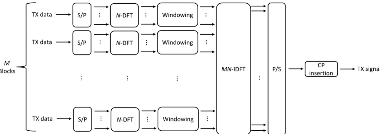
Figure 12: Equivalency of GFDM and DFT-s-OFDM (Transmitter).
GFDM is proposed as a flexible waveform where the number of subsymbols, subcarriers, and prototype filters are adjustable for various channel conditions and use cases. Conceptually, a GFDM signal can also be generated with M FFTs of size N , filter banks, and an M N -point IFFT, as shown in Fig. 12. From this implementation perspective, it is equivalent to a DFT-s-OFDM signal when the rectangular function is used as a prototype filter, which also explains lower PAPR compared to CP-OFDM. This equivalency is further discussed in the following single-carrier waveform discussion. Also, it is equivalent to CP-OFDM when M equals to 1.
GFDM shares the well-frequency-localized characteristic with OQAM-FBMC. Hence, it is suitable for high-mobile scenarios and provides more immunity to synchronization errors. Although GFDM provides flexibility in the waveform, the nonorthogonal transmission scheme requires complex successive interference cancellation (SIC) algorithms at the receiver. Similar to OQAM-FBMC, pilot design and MIMO transmission is complicated. Furthermore, the block-wise transmission causes latency that makes it infeasible for mission-critical applications.
The waveforms that perform subcarrier-wise filtering, that is FBMC and GFDM require a new transceiver design, and there is no backward compatibility with 4G LTE. The next section describes the subband-wise filtered multicarrier schemes and these operations are applicable to the current standards without significant changes.
3) Subband-Wise Filtered MCM:
a) UFMC
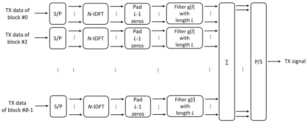
Universal filtered multicarrier (UFMC) [25] applies subband-wise filtering to reduce OOBE. The subband-wise filtering is considered as a compromise between the whole band filtering and subcarrier-wise filtering. Hence, the filters are shorter compared to the FBMC, where the length of filters are much longer than the symbol duration. The total available bandwidth is partitioned into subbands and filtering is performed with a fixed frequency-domain granularity [4]. Considering B subbands (blocks) in total and using a filter of length L, the baseband UFMC signal is represented as follows: sU F M C[k] = B−1 X b=0 L−1 X l=0 N −1 X n=0 dbng[l]ej2πk (n−l) N (5)
TX data of block #0 S/P ∑ P/S TX signal Filter g[l] with length L N-IDFT S/P Filter g[l] with length L N-IDFT S/P Filter g[l] with length L N-IDFT TX data of block #2 TX data of block #B-1 ⋮ ⋮ ⋮ ⋮ ⋮ ⋮ ⋮ ⋮ ⋮ ⋮ ⋮ ⋮ ⋮ ⋮ Pad L-1 zeros Pad L-1 zeros Pad L-1 zeros ⋮ ⋮ ⋮ ⋮
Figure 13: UFMC block diagram (Transmitter).
where db
n is the complex data transmitted on the nth subcarrier and bth subband, and g[l] shows the frequency equivalent windowing function of a time domain finite impulse response (FIR) filter. Therefore, each block length is L + N − 1. The use of CP is optional to provide better immunity against ISI, and it is also called as UF-OFDM when CP is used. However, typical UFMC systems do not utilizes CP and the transitions regions (i.e., ramp-ups and ramp-downs) provide a soft ISI protection. A block diagram of conventional UFMC transmitter is shown in Fig. 13.
The symbols are sent back-to-back without any overlapping, and hence orthogonality in time is maintained. However, the symbols are not circularly convoluted with the channel due to lack of CP and a more complicated receiver is required [26]. A conventional UFMC receiver utilizes an FFT block that has twice the size of IFFT block at the UFMC transmitter.
UFMC provides a better localization in the frequency domain and robustness against time–frequency offsets compared to CP-OFDM. Also, shorter filter lengths compared to subcarrier-wise filtering makes it more suitable for low-latency applications. On the other hand, these shorter filters offer limited OOBE suppression. Furthermore, increased complexity due to the lack of CP and complicated filtering operations should be dealt with intelligently to design practical communications systems.
b) f-OFDM
Filtered-OFDM (f-OFDM) [27] is another subband-wise filtered multicarrier scheme, but the filtering granularity is more flexible than UFMC. The partition in the time–frequency grid is adjusted based on the different channel conditions and use cases, as shown in Fig. 14. This flexibility makes f-OFDM more suitable for the use of different numerologies (such as bandwidth, sub-carrier spacing, CP duration, and transmission time interval) compared to UFMC with the cost of increased complexity. Considering B blocks in total, the baseband f-OFDM signal is represented as follows:
Time (TTI) Frequency (Subband/subcarrier) Block C Block B Block A
Figure 14: An example of flexible resource allocation enabled by f-OFDM.
sf −OF DM[k] = B−1 X b=0 M −1 X m=0 Lb−1 X l=0 N −1 X n=0 dbm,ngb[l]ej2πk (n−l−mLCP ) N (6)
where dbm,n is the complex data transmitted on the bth block, nth subcarrier, and mth subsymbol, gb[l] shows the frequency equivalent windowing function of a time domain FIR filter on the bth block, and L
CP presents the CP size. As can be seen in the equation, f-OFDM maintains the CP in contrast to UFMC. Therefore, it is more immune to the ISI and needs less complex receiver. Ideally, the frequency domain window gb[l] is desired to be a rectangle with a size of Lb. However, it corresponds to an infinite length sinc shape response in the time domain, and hence it is impractical. Therefore, windowed sinc functions are used in the filtering operation. More details on various filters
TX data of block #0 S/P ∑ P/S TX signal N1-IDFT S/P N2-IDFT S/P NB-IDFT TX data of block #2 TX data of block #B-1 CP0 insertion CP1 insertion CPB-1 insertion ⋮ ⋮ ⋮ ⋮ ⋮ ⋮ ⋮ ⋮ ⋮ ⋮ ⋮ ⋮ ⋮ ⋮ Filter g0[l] with length L0 Filter g1[l] with length L1 Filter gB-1[l] with length LB-1 ⋮ ⋮ ⋮ ⋮
can be found in Ref. [19]. A block diagram of conventional f-OFDM transmitter is shown in Fig. 15. Matched filtering and identically sized IFFT/FFT blocks at the receiver also differs f-OFDM from the other subband-wise filtering technique, UFMC.
F-OFDM shares all advantages of well-frequency-localized waveforms such as low OOBE, allowing asynchronous transmission, being feasible for different numerologies, and requiring less number of guard tones. Although f-OFDM cannot provide low OOBE as subcarrier-wise filtered multicarrier schemes due to the use of shorter filter lengths, it is compatible with MIMO transmission scheme and does not require any successive interference cancellation (SIC) algorithm. However, complexity is still the main drawback of f-OFDM compared to CP-OFDM.
B. Single-Carrier Schemes
a) CP-DFT-s-OFDM
Discrete Fourier transform spread OFDM (DFT-s-OFDM) waveforms are proposed to mitigate the high PAPR problem in CP-OFDM while maintaining the useful characteristics of it. The data input can be modeled as independent and identically distributed random variables, and as a result, the corresponding output of IDFT in CP-OFDM has a high variance. Such high variance is reduced by providing correlation to the input data by performing a DFT operation before the IDFT process, as shown in Fig. 16.
The utilization of CP in DFT-s-OFDM ensures circularity of the signal at the receiver and enables easy FDE to handle multipath channel effect. This waveform can be interpreted in two ways [18]. One interpretation is that it is a precoded CP-OFDM scheme, where PAPR is mitigated by DFT precoding. This interpretation provides to consider different precoding methods. The other interpretation is that it is a transmission scheme that upsamples the input data by the ratio of the IDFT and DFT block sizes (i.e., N/M where N > M ), and performs a circular
CP DFT-s-OFDM
TX data S/P M-DFT N-IDFT P/S TX signal
0 0 0 0 CP insertion CP removal RX signal S/P N-DFT FDE M-IDFT P/S RX data Discard Discard (a) (b) ⋮ ⋮ ⋮ ⋮ ⋮ ⋮ ⋮ ⋮ ⋮ ⋮ ⋮
pulse shaping with a Dirichlet sinc function. This interpretation lets the designers consider different pulse shaping approaches to reduce the PAPR further and handle the OOBE.
DFT-s-OFDM is deployed in the uplink of the 4G LTE due to its lower PAPR feature that provides better power efficiency. The low complexity, support of dynamic spectrum access, and MIMO compatibility make CP-DFT-s-OFDM a significant candidate for the 5G, similar to the CP-OFDM. However, the spectral efficiency of this waveform is also comparable to CP-OFDM and suffers from high OOBE because of the discontinuity between adjacent symbols. Hence, similar windowing and filtering approaches as discussed in the multicarrier schemes discussion that can be applied to improve spectral efficiency. In addition to that, internal guard concept for DFT-s-OFDM is being discussed for the 5G, which provides more flexibility in the system design as explained in the following sections.
b) ZT-DFT-s-OFDM
The guard interval is hard-coded in 4G LTE systems, and there exist only two options as normal and extended CP. However, the base station is preset to only one of these guard intervals because the use of different guard interval durations results in different symbol durations and consequently a different number of symbols per frame. This leads to the generation of mutual asynchronous interference even when the frames are aligned [16]. Hence, the users with two different CP durations do not coexist together in the same cell. As a result, the nonflexible guard interval penalizes the user equipments that experience better channel conditions. Zero-tail-DFT-spread-OFDM (ZT–DFT-s-OFDM) [28] is proposed to solve this problem. The CP is replaced with an internal guard period that provides the same functionality. The total period of the guard duration and data duration is fixed, but the ratio between them is flexible as shown in Fig. 17. The flexibility provides better spectral efficiency while maintaining the total symbol duration.
Zero vectors with variable lengths are inserted into the head and tail of the data before DFT process in this approach. The tail length is set to be longer than the delay spread of the channel and, hence the leakage to the next symbol does not have significant power. Also, the zeros in the head, which are usually shorter than the zeros at the tail, provide a smoother transition and yield substantial OOBE reduction [16]. A block diagram of conventional
Figure 17: (a) Flexible internal guard interval. (b) An illustrative example of utilizing flexible internal guard interval in the uplink [18].
RX signal S/P N-DFT FDE M-IDFT P/S Discard zh zeros RX data Discard Discard Discard zt zeros
TX data S/P M-DFT N-IDFT P/S TX signal
0 0 0 0 zt zeros at tail zh zeros at head (a) (b) (a) ⋮ ⋮ ⋮ ⋮ ⋮ ⋮ ⋮ ⋮ ⋮ ⋮ ⋮
Figure 18: ZT-DFT-s-OFDM block diagram. (a) Transmitter. (b) Receiver.
ZT-DFT-s-OFDM transmitter and receiver is shown in Fig. 18.
The fixed sequences (i.e., zero vectors) appended to each symbol ensure circularity at the receiver, and hence ZT-DFT-s-OFDM supports single-tap FDE. However, a residual energy of the data part in the last samples introduces a noncyclical leakage to the next symbol [16] and hence, internal guard interval approach do not provide perfect circularity as CP does. Furthermore, this leakage is a limiting factor in the link performance for the users utilizing high-order modulations in a multipath environment.
The PAPR and OOBE are low for ZT-DFT-s-OFDM, and spectral efficiency is increased due to flexible guard interval. The internal guard feature makes it suitable for different symbol durations without introducing mutual asynchronous interference. However, this flexibility causes extra overhead to track delay spread of the channel. Also, windowing can easily be applied to decrease OOBE without further extra guard duration.
c) UW-DFT-s-OFDM
Unique word DFT-spread OFDM (UW-DFT-s-OFDM) [29] is another single-carrier scheme that utilizes flexible internal guard band. The zero tails and heads of the ZT–DFT-s-OFDM are replaced with a fixed sequence that enhances cyclic properties of the signal in this approach. Since the fixed sequence is inserted before the DFT process as shown in Fig. 19, the orthogonality is provided between the data and the unique word. The circularity is also ensured in this waveform and as a result simple FDE is supported. However, the leakage from the data part limits its link performance for the high-order modulations similar to ZT-DFT-s-OFDM.
Different from the ZT part, UW can also be exploited for synchronization and channel tracking purposes [30]. Therefore, it improves spectral efficiency. The OOBE leakage characteristics of this waveform are comparable to ZT–DFT-s-OFDM since the continuity of the symbols are provided with the DFT block. Adding data-dependent “perturbation” signal or modifying the kernel function with windowing the input data (which is analogous to GFDM
N-IDFT P/S TX signal M-DFT 0 0 0 0 TX data S/P UW S/P RX signal S/P N-DFT FDE M-IDFT Discard Discard S/P S/P RX data UW removal (a) (b) ⋮ ⋮ ⋮ ⋮ ⋮ ⋮ ⋮ ⋮ ⋮ ⋮ ⋮ ⋮ ⋮
Figure 19: UW-DFT-s-OFDM block diagram. (a) Transmitter. (b) Receiver.
with UW) mitigates the OOBE and PAPR further [18]. However, these benefits come with increased complexity.
IV. SUMMARY
The frequency localization is important to allow asynchronous transmission across adjacent subbands and coex-istence with other waveforms. On the other hand, the time localization is critical for low latency applications where longer filter/window durations are not feasible for URLLC. All discussed waveforms for 5G provide lower OOBE compared to CP-OFDM and its single-carrier equivalent, that is, CP-DFT-s-OFDM. The subcarrier-wise filtering operation in FBMC results in the best frequency localization among the candidate waveforms due to the use of longer filter lengths. Although GFDM is another subcarrier-wise filtered waveform, the rectangular window shape in the time domain causes abrupt transitions and increases OOBE. However, windowing can be performed on this waveform, and W-GFDM presents a good spectral confinement as well. Furthermore, relatively shorter filters in the subband-wise filtered waveforms lead to a better time localization with a price of increasing the OOBE compared to the subcarrier-wise filtered waveforms.
Most multicarrier schemes suffer from high PAPR and are not suitable when high energy efficiency is required. However, GFDM exhibits a reduced PAPR characteristic due to its equivalency to DFT-spread waveforms, as discussed before. The single-carrier schemes are preferable in energy-limited use cases along with the use of flexible guard intervals that provide better spectral confinement and improved PAPR.
The spectral efficiency is another critical design criteria that is highly affected by the window/filter duration, the shape of filter, and extra overheads. Well-frequency-localized waveforms reduce the need for guard bands and hence leading to better efficiency in the frequency domain. On the other hand, the waveforms that do not utilize a guard interval, such as FBMC, are expected to have higher efficiency in the time domain. However, BER/BLER performance decreases substantially in a multipath fading channel due to lack of guard interval. As a result, complex
receivers are required since an easy FDE is not possible. MIMO compatibility is also essential to achieve high throughput. The schemes that allow interference, such as FBMC and GFDM, cannot deploy straightforward MIMO algorithms.
Finally, the guard interval in the time domain makes a waveform more robust against ISI and time-offsets. In addition, the guard bands or the use of well-localized waveforms in the frequency domain make a waveform robust against carrier frequency offset and Doppler effects that reduce ICI and adjacent channel interference (ACI) in a multiple access environment. As a result, FBMC has the best immunity to ICI and is the most vulnerable to ISI.
A summary of the main advantages/disadvantages of these major 5G candidate waveforms is provided in Table II. Moreover, the time–frequency grids, OOBE, and the pulse shapes of these waveforms are presented in Fig. 20 and Fig. 21.
Table II: The 5G waveform candidates.
Multicarrier Schemes
Waveform Advantages Disadvantages
CP-OFDM
• Simple FDE • Easy MIMO integration • Flexible frequency assignment • Low implementation complexity
• High OOBE and PAPR
• Strict synchronization requirement
• Poor performance for high mobility applications • Hard-coded CP
W-OFDM • All advantages belongs to CP-OFDM• Lower OOBE compared to CP-OFDM • Either poor spectral efficiency or BER performance (depending on windowing type)
OQAM-FBMC
• Best frequency localization (i.e., lowest OOBE) • Good spectral efficiency (no guard band or CP) • Suitable for high-mobility applications • Convenient for asynchronous transmission
• Challenging MIMO integration and pilot design • No immunity to ISI due to lack of CP • High implementation complexity
• Increased power consumption due to OQAM signaling
GFDM
• Flexible design
• Good frequency localization • Reduced PAPR
• Higher latency due to block processing • Challenging MIMO integration and pilot design • High implementation complexity
UFMC
• Good frequency localization
• Shorter filter length compared to subcarrier-wise operations (i.e., OQAM-FBMC and GFDM ) • Compatible with MIMO
• No immunity to ISI due to lack of CP
• High receiver complexity due to increased FFT size
F-OFDM
• Flexible filtering granularity • Better frequency localization
• Shorter filter length compared to subcarrier-wise operations (i.e., OQAM-FBMC and GFDM ) • Compatible with MIMO
• Very high implementation complexity
Single-carrier Schemes
Waveform Advantages Disadvantages
CP-DFT-s-OFDM • All advantages belongs to CP-OFDM• Low PAPR
• High OOBE
• Strict synchronization requirement • Hard-coded CP
ZT-DFT-s-OFDM
• Flexible guard interval • Better spectral efficiency
• Lower OOBE compared to CP-DFT-s-OFDM
• Strict synchronization requirement • Extra control signaling
• Limited link performance for higher order modulation
UW-DFT-s-OFDM
• Flexible guard interval • Best spectral efficiency • Lowest OOBE and PAPR
• Strict synchronization requirement • Extra control signaling
• Limited link performance for higher order modulation • High implementation complexity
t f CP T OOBE OOBE t f W CP T W OOBE OOBE t
f
In-phase Quadrature-phase t fCP
T
dm,n t f T L/2 L/2 OOBE OOBE CP t f T L/2 L/2 OOBE OOBE (e) (f) (c) (d) (a) (b)...
...
...
...
...
...
...
...
...
Figure 20: Comparison of multicarrier schemes. (a) CP-OFDM, (b) W-OFDM, (c) OQAM-FBMC, (d) GFDM, (e) UFMC, and (f) f-OFDM.
t f CP T t f T Zh or UW OOBE Supressed OOBE Zt or UW (a) (b)
...
...
...
...
Figure 21: Comparison of single-carrier schemes. (a) CP-DFT-s-OFDM. (b) ZT-DFT-s-OFDM or UW-DFT-s-OFDM.
V. CONCLUSIONS
In this chapter, the ongoing new radio design discussions are summarized, and the major waveform candidates for 5G and beyond are presented. The main 5G use cases are identified along with the associated critical design requirements, and a brief description of CP-OFDM is provided as a baseline for the new waveform discussion. The candidate waveforms are classified considering the way the spectrum is utilized (i.e., single-carrier versus multicarrier), the fashion in which the signal processing techniques are performed (i.e., windowing, subcarrier-wise filtering, and subband-wise filtering), and the guard interval type that is adopted (i.e., internal and external). The advantages and disadvantages of each waveform are discussed in detail. It could be concluded that there is no waveform that fits all requirements yet and the physical layer should be designed considering the specific use cases and requirements. Unlike the previous standards, the new generations will support high flexibility to fully exploit and increase further the potential of future communications systems.
REFERENCES
[1] M. Elkourdi, B. Peköz, E. Güvenkaya, and H. Arslan, “Waveform design principles for 5G and beyond,” in 2016 IEEE 17th Annual Wireless and Microwave Technology Conference (WAMICON), Apr. 2016, pp. 1–6.
[2] ITU-R, “IMT Vision - Framework and overall objectives of the future development of IMT for 2020 and beyond,” Technical Report M.2083-0, Sept. 2015.
[3] Qualcomm Inc., “Waveform Requirements,” 3GPP Standard Contribution (R1-162198), Busan, Korea, Apr. 11-15 2016. [4] X. Zhang, L. Chen, J. Qiu, and J. Abdoli, “On the Waveform for 5G,” IEEE Commun. Mag., vol. 54, no. 11, pp. 74–80, 2016. [5] Huawei, HiSilicon, “5G waveform: requirements and design principles,” 3GPP Standard Contribution (R1-162151), Busan, Korea, Apr.
11-15 2016.
[6] A. Sahin, I. Guvenc, and H. Arslan, “A survey on multicarrier communications: prototype filters, lattice structures, and implementation aspects,” IEEE Communications Surveys Tutorials, vol. 16, no. 3, pp. 1312–1338, 2014.
[7] I. F. Akyildiz, W. Su, Y. Sankarasubramaniam, and E. Cayirci, “A survey on sensor networks,” IEEE Commun. Mag., vol. 40, no. 8, pp. 102–114, 2002.
[8] A. F. Demir, Z. E. Ankarali, Q. H. Abbasi, Y. Liu, K. Qaraqe, E. Serpedin, H. Arslan, and R. D. Gitlin, “In vivo communications: steps toward the next generation of implantable devices,” IEEE Veh. Technol. Mag., vol. 11, no. 2, pp. 32–42, 2016.
[9] A. F. Demir, Q. Abbasi, Z. E. Ankarali, A. Alomainy, K. Qaraqe, E. Serpedin, and H. Arslan, “Anatomical region-specific in vivo wireless communication channel characterization,” IEEE J. Biomed. Health. Inf., vol. 21, no. 5, pp. 1254–1262, 2017.
[10] C. Urmson and W. Whittaker, “Self-driving cars and the urban challenge,” IEEE Intell. Syst., vol. 23, no. 2, pp. 66–68, 2008.
[11] M. Hafez and H. Arslan, “On directional modulation: an analysis of transmission scheme with multiple directions,” in 2015 IEEE International Conference on Communication Workshop (ICCW), June 2015, pp. 459–463.
[12] T. Hwang, C. Yang, G. Wu, S. Li, and G. Y. Li, “OFDM and its wireless applications: a survey,” IEEE Trans. Veh. Technol., vol. 58, no. 4, pp. 1673–1694, 2009.
[13] Y. Rahmatallah and S. Mohan, “Peak-to-average power ratio reduction in OFDM systems: a survey and taxonomy,” IEEE Communications Surveys Tutorials, vol. 15, no. 4, pp. 1567–1592, 2013.
[14] A. F. Demir and H. Arslan, “The impact of adaptive guards for 5G and beyond,” in 2017 IEEE 28th Annual International Symposium on Personal, Indoor, and Mobile Radio Communications (PIMRC), Oct. 2017, pp. 1–5.
[15] Qualcomm Inc., “Waveform candidates,” 3GPP Standard Contribution (R1-162199), Busan, Korea, Apr. 11-15 2016.
[16] G. Berardinelli, K. I. Pedersen, T. B. Sorensen, and P. Mogensen, “Generalized DFT-spread-OFDM as 5G waveform,” IEEE Commun. Mag., vol. 54, no. 11, pp. 99–105, 2016.
[17] H. Lin and P. Siohan, “Major 5G waveform candidates: overview and comparison,” in Signal Processing for 5G. John Wiley & Sons, Ltd, 2016, pp. 169–188.
[18] A. Sahin, R. Yang, E. Bala, M. C. Beluri, and R. L. Olesen, “Flexible DFT-S-OFDM: solutions and challenges,” IEEE Commun. Mag., vol. 54, no. 11, pp. 106–112, 2016.
[19] B. Farhang-Boroujeny, “OFDM versus filter bank multicarrier,” IEEE Signal Process. Mag., vol. 28, no. 3, pp. 92–112, 2011. [20] A. Sahin and H. Arslan, “Edge windowing for OFDM based systems,” IEEE Commun. Lett., vol. 15, no. 11, pp. 1208–1211, 2011. [21] Samsung, “Discussion on Multi-Window OFDM for NR Waveform,” 3GPP Standard Contribution (R1-166746), Gothenburg, Sweden,
Aug. 22-26 2016.
[22] Rohde & Schwarz, “5G waveform candidates,” Technical report, 2016.
[23] H. Lin, “Flexible configured OFDM for 5G air interface,” IEEE Access, vol. 3, pp. 1861–1870, 2015.
[24] N. Michailow, M. Matthé, I. S. Gaspar, A. N. Caldevilla, L. L. Mendes, A. Festag, and G. Fettweis, “Generalized frequency division multiplexing for 5th generation cellular networks,” IEEE Trans. Commun., vol. 62, no. 9, pp. 3045–3061, 2014.
[25] V. Vakilian, T. Wild, F. Schaich, S. t. Brink, and J. F. Frigon, “Universal-filtered multi-carrier technique for wireless systems beyond LTE,” in 2013 IEEE Globecom Workshops (GC Wkshps), Dec. 2013, pp. 223–228.
[26] F. Schaich, T. Wild, and Y. Chen, “Waveform contenders for 5G - suitability for short packet and low latency transmissions,” in 2014 IEEE 79th Vehicular Technology Conference (VTC Spring), May 2014, pp. 1–5.
[27] X. Zhang, M. Jia, L. Chen, J. Ma, and J. Qiu, “Filtered-OFDM - enabler for flexible waveform in the 5th generation cellular networks,” in 2015 IEEE Global Communications Conference (GLOBECOM), Dec. 2015, pp. 1–6.
[28] G. Berardinelli, F. M. L. Tavares, T. B. Sorensen, P. Mogensen, and K. Pajukoski, “Zero-tail DFT-spread-OFDM signals,” in 2013 IEEE Globecom Workshops (GC Wkshps), 2013, pp. 229–234.
[29] A. Sahin, R. Yang, M. Ghosh, and R. L. Olesen, “An improved unique word DFT-spread OFDM scheme for 5G systems,” in 2015 IEEE Globecom Workshops (GC Wkshps), 2015, pp. 1–6.
[30] J. Coon, M. Sandell, M. Beach, and J. McGeehan, “Channel and noise variance estimation and tracking algorithms for unique-word based single-carrier systems,” IEEE Trans. Wireless Commun., vol. 5, no. 6, pp. 1488–1496, Jun. 2006.
AUTHORINFORMATION
Ali Fatih Demir received the B.S. degree in electrical engineering from Yildiz Technical University, Istanbul, Turkey, in 2011, and the M.S. degree in electrical engineering and applied statistics from Syracuse University, Syracuse, NY, USA in 2013. He is currently pursuing the Ph.D. degree as a member of the Wireless Communication and Signal Processing (WCSP) Group in the Department of Electrical Engineering, University of South Florida, Tampa, FL, USA. His current research interests include waveform design, multicarrier systems, in vivo communications, and brain–computer interfaces. He is a student member of the IEEE.
Mohamed H. Elkourdi received the B.Sc. degree in telecommunication and electronics engineering with distinction from Applied Science University, Amman, Jordan, in 2010, and the M.S. degree in telecommunication and signal processing from New Jersey Institute of Technology, Newark, NJ, USA in 2013. He is currently pursuing the Ph.D. degree as a member of the Innovation in Wireless Information Networking Laboratory (iWINLAB) in the Department of Electrical Engineering, University of South Florida, Tampa, FL, USA. His current research interests include waveform design, multicarrier systems, multiple access techniques, and MIMO systems.
Mostafa Ibrahim received the B.Sc. degree from Ain Shams University, Cairo, Egypt in 2010, and the M.Sc. degree from Istanbul Medipol University, Istanbul, Turkey, in 2017, both in electronics and communication engineering. Prior to joining the Communications, Signal Processing, and Networking Center (CoSiNC) at Istanbul Medipol University in 2015, he was with the Egyptian Air Force, where he was a communication engineer officer (2011–2013), and with the Center for Nanoelectronics and Devices (CND) at the American University in Cairo, where he worked on on-chip energy harvesting systems optimization (2013–2014). His current research interests include air–ground channel modeling and waveform/modulation design beyond OFDMA.
Huseyin Arslan received the B.S. degree from Middle East Technical University, Ankara, Turkey, in 1992 and the M.S. and Ph.D. degrees from Southern Methodist University, Dallas, TX, USA, in 1994 and 1998, respectively. From January 1998 to August 2002, he was with the research group of Ericsson Inc., NC, USA, where he was involved with several projects related to 2G and 3G wireless communication systems. Since August 2002, he has been with the Department of Electrical Engineering, University of South Florida, Tampa, FL, USA, where he is a professor. In December 2013, he joined Istanbul Medipol University, Istanbul, Turkey, where he has worked as the Dean of the School of Engineering and Natural Sciences. His current research interests include waveform design for 5G and beyond, physical layer security, dynamic spectrum access, cognitive radio, coexistence issues on heterogeneous networks, aeronautical (high-altitude platform) communications, and in vivo channel modeling and system design. He is currently a member of the editorial board of the Sensors Journaland the IEEE Surveys and Tutorials. He is a fellow of the IEEE.
View publication stats View publication stats
![Figure 1: Waveform definition [6].](https://thumb-eu.123doks.com/thumbv2/9libnet/5439557.104276/2.918.214.701.101.335/figure-waveform-definition.webp)
![Figure 7: Edge windowing technique [20].](https://thumb-eu.123doks.com/thumbv2/9libnet/5439557.104276/7.918.184.725.107.211/figure-edge-windowing-technique.webp)
![Figure 8: Edge windowing block diagram [21].](https://thumb-eu.123doks.com/thumbv2/9libnet/5439557.104276/8.918.175.734.98.562/figure-edge-windowing-block-diagram.webp)