An e x a m i n a t i o n of the e f f e c t of
polarization on the radiation losses of
bent optical fibres
A . A L T I N T A $
Bilkent University, Department of Electrical and Electronics Engineering, Bilkent, 06533 Ankara, Turkey
S. G. T A N Y E R
Washington State University, School of Electrical Engineering and Computer Science, Pullman, WA 99164, USA
Received 29 January; revised 26 August; accepted 16 September 1992
It has long been recognized that the bending losses in weakly guiding optical fibres are independent of the polarization for large bend radius. Here, we show this fact using the volume equivalent current method. The procedure is then applied to a helically bent fibre and it is shown that the radiation from the helical fibre is also independent of the polarization as long as the fibre is weakly guiding.
1. I n t r o d u c t i o n
It is well understood that a bent fibre radiates energy. It has been assumed that this radiation is independent of the polarization for large bend radius [1, 2]. This fact can be illustrated by the equivalent current method of Snyder and Love [2] as described in Section 3.
In the case o f a helical fibre, the radiation is due to bending loss and helical loss [3]. If a multimode fibre is bent into a helix, the radiation acts as an effective cutoff for modes [4]. In the previous analyses, the polarization is assumed to stay parallel to a rectangular coordinate axis which is invariant with respect to the helical path. However, in reality, it is well k n o w n that the polarization slips back owing to the torsion of the helix [5]. Thus, one needs to include this rotation of polarization in the radiation calculations. We have performed this analysis and observed that the total radiation is independent o f the polarization slip.
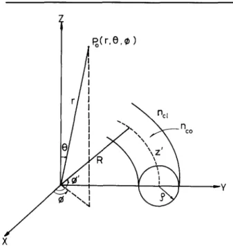
2. Analysis for a circularly bent fibre
The circularly bent fibre is shown in Fig. l. The fibre has a core radius p, core refractive index nco and cladding index no1. The fibre and index parameters are denoted by V, and A 2 2 2 )/2n2o, where k = 27r/Ao and Ao is the free-space as V = kp(n2o - ncl) 1/2, A = ( n c o - ncl
wavelength. R c is the radius o f curvature o f the bend and it is assumed to be large
A. Altinta# and S. G. Tanyer
l1 IPo(r.O.r
X
Lu
Figure 1
Circularly
bent
fibre.
compared to p to satisfy the slowness criteria (equation 19-17 o f [2]): Rc>> 47r V
P V ~ W2 (1)
where W = p(fl2 - k ncl ) 2 2 1/2 and /3 is the phase constant of the mode. As a typical example, for the following parameters:
nco = 1.560 nc] = 1.557 V = 3.574 A = 0.006 the slowness criterion gives
Ao = 850 nm p = 5 # m U = 1.857 W = 3.055
Rc/p>>43.929 (2)
which is satisfied for the bend radius in the range of a few millimetres.
The equivalent current method follows from Maxwell's equations. The core region of the bent fibre is replaced by an equivalent volume current o f strength
J = ik(eO~ 1/2 \#0./ (no2~ - no2 ) E (3) where E is the field in the core. If E is known or approximated then the radiation from the fibre is calculated by antenna theory. The easiest approximation, which is known to be valid when the slowness criteria is satisfied [2], is to take E as the mode in the core without any modifications. The radiation loss obtained by this method has been shown to agree with previous results [4].
In previous calculations, the core field is assumed to be linearly polarized in the direction perpendicular to the plane of the bend. Henceforth, this will be referred to as the 'perpendicular polarization' case. Here in this paper, we will be analysing the 'parallel polarization' case in which the core field is linearly polarized in the direction parallel to the plane of the bend (Fig. 1). The equivalent current in this parallel polarization case is given by
(e~ ~l/2k(n2 -
no2) E~c (4)J = i \~00/
where ~i c is the unit vector along the radial direction away from the centre of curvature of the bend. For the single mode fibre, the electric field strength E is given by
e = ei~ZFo(R)
(5)
Jo(UR)/Jo(U)
coreFo(R) = [, Ko(WR)/Ko(W)
cladding withwhere J0, K0 are Bessel functions of order 0, z is the distance along the fibre, R =
r/p,
and the parameter U is given byU -- p ((knco) 2 - 3 2 )1/2
Accordingly, the vector potential (equation 21-20 of [2]) is given as follows:
M =
IcR~
exp {iRe [r - kd sin 0 cos (4 - 4' )]}x [a0 cos 0 cos (q~ - q~') + ~i~ sin (4~ - q~')] d4~' (6) where
Ic =27rp2fl#RdR,
and # = [J[, k~l =kncl and z is approximated by Rcq~'. In Equation 6, only the transverse part which contributes to radiation is included. A careful examination of the above integral shows that the integrand oscillates quite rapidly except at stationary phase points which are given by3 + k c l sin 0 sin(~b- 4') = 0 (7) which yields
sin (4 - ~b') - fl
kcl sin O (8) Using these values, the integral in Equation 6 is well approximated by
( ~ ( 3 ) 2
-fl )27rRclc'lJ~(kclRcsinO)l
(9)
M = a0 cos 19 1 - kcl sin 0 + as kcl sin 0where u =flRc >> 1. The total radiated power in the far zone is given by
Prad
IMoI 2 +IM, I 2]
sin 0d0d~b(10)
J0 30
where a =
(k2nel/327r 2)
(#0/e0) V2. Substituting Equation 9 into Equation 10 and setting 107A. Altinta# and S. G. Tanyer nco ~ ncl, we obtain Brad = 8 ~ - \ ~ o / - - - - where v ~ I~ g
j2 (kRcncl
g/co m J0 sin O)(f2(O) + f~(O))dO (I1)
f l ( 0 ) = c o s 0 1 - ~:clsin0
/3
f2(0) - kcl sin 0
If we use Debye's approximate value for the Bessel function in the integrand, we get 1 Rc (#~ V2/c2 I2 sin OQ(O)
Prad ---- g ~ \s nco A (/32 2 k ~ ~ 0)1/2 es(~ dO
where
and
2kcl c
;2
S(O) - 3 sin---5 0 kc] - sin: 0
(12)
(13)
Q(O) = f2(O) + fff(O) (14)
Now, we can search for a stationary phase point of the above integral.
os(o)
o 0 - 0 (15)
=~ ~c]-sin2 0 - ~ s i n 2 0-k--~l-sin2 0 = 0 (16) / 3 2
=* sin 2 0 = k~ = 1 (17)
Therefore the stationary phase point is very close to zr/2, so that 0 = 7r/2 can be substituted into the coefficient function of the Bessel function in the integrand. Then we get
exp ( (18)
"rad = -'-~12 (Rc~ 1/2 (~0~ 1/2
V2
Hco 4 R c AW3~32"c \ P / \-%0/ W3/2 A 3 p
V 2 ]
which is the same result as in the perpendicular polarization case [2]. It is also noted that, in the asymptotic evaluation of Equation 11, the contribution from 114o is zero (since
fl (0) = 0 at 0 = ~r/2). For the perpendicular polarization case the contribution from M e is zero. The radiated fields of both polarizations are orthogonal, so the power loss is additive for the parallel and perpendicular components of an arbitrarily polarized field.
ncl
Y
Po(r,O .~)
~ ~ r ~ Z
_p .
Figure 2 Hehcally bent fibre
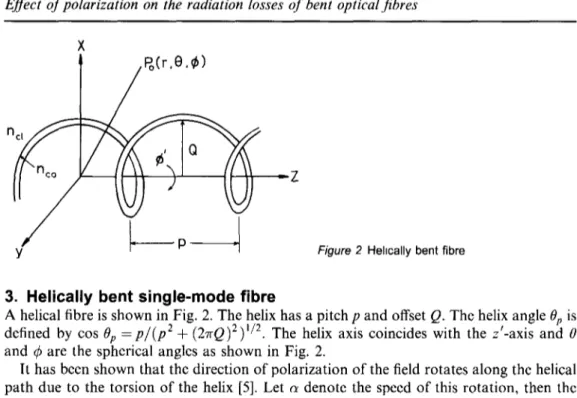
3. Helically bent single-mode fibre
A helical fibre is shown in Fig. 2. The helix has a pitch p and offset Q. The helix angle Op is defined by cos Op = p / ( p 2 + (27rQ)2)V2. The helix axis coincides with the z'-axis and 0 and q~ are the spherical angles as shown in Fig. 2.
It has been shown that the direction of polarization of the field rotates along the helical path due to the torsion of the helix [5]. Let c~ denote the speed of this rotation, then the equivalent current is given by
Jeq = [fix cos a ~ t -1- fly sin a~b']# (19) in the core region, with # being the magnitude in Equation 1. The vector potential becomes M = , L M x + .yM~,
(20)
where To get the Substituting we obtain L M ~ = # I _ L e x p l - J ( c ~ s o p - k c l c ~[2~, ]
- j k c l Q s i n O c ~ cos ~ a ~ - z ) dz' (21) sin ( a - ~ z ' )radiation from a helix of infinite length, L must be taken to infinity.
M~ = - M x sin q~ + My cos ~ and M o = M,: cos ~ cos O + My sin ~b sin O,
U f27r
Prad ~-crJ0 J0
[IM~12(sin2 q~+ c~ ~ c ~ 0) + IMyl2(cos2 4~ + cos 2 0 sin 2 q~)+ rMxllMy I
sin 4~ cos 4~(cos 2 0 - 1)] sin 0 d 0 d ~ (22) It is also noted that the last term in the integrand vanishes after the ~b-integration. UsingA. Altinta~ and S. G. Tanyer
the following decompositions,
cos f 27r ,'~
~ a p Z ) = ~ [ e x p ( j a ~ z ' ) + e x p ( - j a ~ z ' ) ]
1f 27r ,'~
1
f. 27r ,'~
s i n ~ a p Z ) : ~ [ e x p ~ - f f z ) - e x p ( - j a ~ z ' ) ]
Equation 21 can be written as
Mx =Mxa+Mx~
M y = M y a - M y b where and,i ~ [~.(~
~;)]
= exp - kcl cos0 :~ a
z t
Mxab "2 -L
cos Op
• exp [-jkclQ Sin O cos ( $ - ~ z ' ) l
d f
.~
~
cos0~o~)z]
M y ~ = ~ ) f _ L e x p [ - J ( ~ - k c l
x exp [-jkclQ sin O cos ( ~ - ~ z ' ) l dz'
The radiated power expression can be written as
Prad =
[ [ Mxa + M xb l 2 ( sin 2 (9 + cos 2 c) cos z O)
j0 jo
+ IMy= -Mybl2(cos2(9+cos 2 0
sin 2 ~b)] sin 0d0d~bUsing the relation
exp
(-jz
cos O) =Jo(z) + 2 ~ (j)mJm(z)
COS(mO)
m = l
we have
where
Mx; = ~ Jo(kcxQ
sinO)Foab + 2
(j)mJm(kcl
Q
sinO)Fm;
m = l
My. h = ~ Jo(kclQ
sinO)Fo; + 2
(j)mJm(kcl
Q
sinO)Fm;
m = l L /3 kcl 0 4- o~27r 2 7r )
[(
~os
+7)]
sin ~ Op p~=oxpjmO (~
~cosO~~
/~ Cos 0~ p 110 (23) (24) (25) (26) (27) (28) (29)(30)
(31)
(32)L fl a27r 2 } sin[ (co--0-~-- - kcl cos 0 + - - p~-)]
Op
p
(33)+ e x p - j m r
L ( /3
kcl COS O • a27r 2
co;
o,
7
t ,Each term has a
(sinx)/x
behaviour which has a maximum at those points where thedenominator vanishes and it is essentially zero everywhere else, since we are interested in the limit L ---* ec. Therefore, the doubly infinite set of terms in
IMx;[ a and
IMy;12
simplify to the following:2
rsin E ;l?
tMx~l 2 ~- [ Mk@ 2= ~ L2jo2(kclQ sin 0 ) L ~ J [sin2[B;] sin2[C;]- (34)q-lz2L2 ~--~ j2(kclQ sin O)[ [-~"b]2
[C~] 2 whereA~= (cosOp kdcos
( 27r 2:,rr) = L fl kd cos 0 qz a ~ + (36)
B;
cos G
P
( 27r 2pTr) (37) L fl kcl cos 0 T a C~b = cOS Op pThe cross terms in [Mx] 2 and
IMyl 2
containmxaMxb
orMyaM~*,b,
respectively (thesuperscript (*) denotes complex conjugation). These terms are equal in magnitude and their total contribution to the integral in Equation 29 is zero. Since the speed a is given by
a = cos (Op) (38)
for vanishingly small fibre thickness compared with the radius of the curvature, some of the (sin x)/x functions will have peaks at imaginary values of 0. The contribution of these peaks at imaginary values of 0 has to be discarded for the power loss calculation (as in array antennas), and I M~;I 2 is written as
2 Isin2[A~] ]
]Mx;] 2
=~-t2~(kcla
sin 0)[ [ - ~ ] 2 j m = mma x+ #2L2 Z m ~ m m m
where m are values for which
J2m(kclQ
sin 0) -sin 2[B~] sin 2[C~]1 (39)/3 a27r 2mTr
- - -
(40)
cos 0m kcl C O S Op T
Pkcl pkcl
yields a value of 0m between 0 and 7r. The expression for [MyZ[ 2 is exactly the same, in other words,
[Mx~] 2
= ]My~] 2 = ]M~I 2 (41)A. Altinta~ and S. G. Tanyer
Substituting these in Equation 29, and noting that I M~] 2 is independent of q~, we get Brad = 27rcr 2 + IMbl2)(1 + c o s 2 0) sin 0d0 (42) Defining
( /3 0T~27r 2pTr)
q:F = L c ~ s Op - kcl cos P -- (43)
dq~_ = Lkcl sin 0 dO (44)
the integral in Equation 42 becomes
1
Brad = 27rcr#2L2 Z JZ(kclQ sin 0m)(1 + c o s 20m) Lkd m
[jz+sin ,q+,
l: sin',q, ]
x :- q+2 dq+ + q----7_2 dq_ (45)
where z + and z - correspond to the values of q-L when m goes from mmm to mma x. If we now increase L indefinitely, the integrals have value ~r, so
Brad 47r2~ 2L
-- kr ~ J~(kclQ sin 0m)(1 +COS 2 0m) (46)
m
This expression is exactly the same as found in previous analyses (equation A17 of [4]) which neglected the rotation of the direction of polarization.
4. Conclusions
We have demonstrated that the equivalent current method can be employed to predict the bend loss in an optical fibre for both orthogonal polarizations of modal field. The same analysis is then carried out for a helically bent fibre and it is observed that rotation of polarization due to the torsion does not affect the radiation loss.
Acknowledgements
We thank Dr John D. Love of Australian National University for his inspiration and help. We also appreciate the comments and suggestions of the reviewers. This work is supported in part by N A T O - A G A R D , Guidance and Control Panel.
References
1. D. CHANG and E. F. KUESTER, IEEE J. Quantum Electron. l l (1975) 903.
2. A W SNYDER and J. D. LOVE, Optical Waveguide Theory ( C h a p m a n and Hall, London, 1983). 3. J. D LOVE and A. W. SNYDER, Electron Lett. 23 (1987) 1109.
4. A ALTINTA~; and J. D. LOVE, Opt. Quantum Electron. 22 (1990) 213. 5. J. N ROSS, Opt. Quantum Electron. 16 (1984) 455.
6. S G TANYER, M.S. Thesis (Bilkent University, Ankara, Turkey, 1990) p. 25.