Microwave Imager Design with 2.46 GHz Microstrip Patch Antennas
Fatih Özkan ALKURT1, Muharrem KARAASLAN1, Emin ÜNAL1, Faruk
KARADAĞ2,*
1Iskenderun Technical University, Faculty of Engineering and Natural Sciences, Department of Electrical-Electronics Engineering, 31200, Hatay, Turkey
[email protected], ORCID: 0000-0002-9940-0658 [email protected], ORCID: 0000-0003-0923-1959
[email protected], ORCID: 0000-0002-4088-8353
2Cukurova University, Faculty of Art and Science, Department of Physics, Balcali, Adana, Turkey [email protected], ORCID: 0000-0001-7862-9085
Abstract
In this study, microwave imager design is aimed by using a series of microstrip patch antennas operating in the 2.46 GHz frequency band. The designed microwave imager has a 24-sided cylindrical shape and includes 5x1 microstrip patch antennas placed at 45˚ angles. The overall working principle of the microwave imager is based on the back reflection and transmission values between the transmitter and receiver antennas. The 40 microstrip patch antennas inside the microwave imager operate as both a receiver and a transmitter and the transmission values between each other (S21, S31, S41, S21 etc.) are capable of mapping the internal space in three dimensions with the required algorithm. The microstrip antennas in the designed structure have been chosen for their small volume, easy integration, versatility, low profile, and the most commonly used 2.46 GHz frequency is used as the operation band. The most important achievement of this study is to support medical imaging practices; the detection of cancerous areas such as breast cancer can be determined by the interaction between antennas and is the aim of this study. In addition, the developed microwave imager can also be used in concrete mapping and
Adıyaman University Journal of Science https://dergipark.org.tr/en/pub/adyujsci
DOI: 10.37094/adyujsci.552323
ADYUJSCI
9 (2) (2019) 404-416
non-destructive imaging applications in the construction sector. Besides, the designed configuration has another advantage due to its low cost.
Keywords: Microwave imaging, Patch antenna, Array antenna
2.46 GHz’te Mikroşerit Yama Antenlerle Mikrodalga Görüntüleyici Tasarımı Öz
Bu çalışmada 2.46 GHz frekans bandında çalışan mikroşerit yama antenlerin bir serisi kullanılarak mikrodalga görüntüleyici tasarımı amaçlanmıştır. Tasarlanan mikrodalga görüntüleyici 24 kenarlı silindirik şekle sahip ve 45o açılarla yerleştirilmiş 5x1 mikro şerit yama antenler içermektedir. Mikrodalga görüntüleyicinin genel çalışma prensibi, verici ve alıcı antenleri arasındaki geri yansıma ve iletim değerlerine dayanmaktadır. Mikrodalga görüntüleyicinin içindeki 40 mikro şerit yama anteni hem alıcı hem de verici olarak çalışır ve birbirleri arasındaki iletim değerleri (S21, S31, S41, S21 vb.) iç alanı gerekli algoritma ile üç boyutlu olarak haritalayabilirler. Tasarlanan yapıdaki mikro şerit antenler küçük hacimleri, kolay entegrasyonu, çok yönlülükleri, düşük profilli olmaları için seçilmiş ve en yaygın kullanılan 2.46 GHz frekansı çalışma bandı olarak kullanılmıştır. Bu çalışmanın en önemli yanı tıbbi görüntüleme uygulamalarını desteklemektir; meme kanseri gibi kanser vakalarında kanserli alanların tespiti antenler arasındaki etkileşimle belirlenebilir ve bu çalışmanın amacıdır. Ayrıca, geliştirilen mikrodalga görüntüleme cihazı inşaat sektöründe beton haritalama ve tahribatsız görüntüleme uygulamalarında da kullanılabilir. Bunlardan başka, tasarlanan konfigürasyonun düşük maliyetli olması başka bir avantajıdır.
Anahtar Kelimeler: Mikrodalga görüntüleme, Yama anteni, Dizi anten
1. Introduction
Today, the non-destructive visualization and mapping of an object or structure has become very important. The reason for this is the development of areas such as defense, security, medical, food, building industry and the need for imaging in these areas. To address this need, studies have been carried out on high frequency electromagnetic waves with low wavelength. Paulsen et al. developed an algorithm in 1999, they performed tumor and bone imaging in the medical area with microwaves in the 500-900 MHz range
[1, 2]. In another study conducted in the medical field, Li and Hagness have managed to visualize breast cancer location in two dimensions by using a very wide band antenna and a high efficiency algorithm [3]. In other studies, following this perspective, the tumor location was identified as three-dimensional [4, 5].
In the medical area, microwave imaging studies were mostly on breast cancer detection, for example, adaptive multistatic microwave imaging was performed and a series of antenna were used as receptors of scattered signals [6]. In addition, Nilavalan et al. developed an ultra-wide band microstrip patch antenna operating between 4-9.5 GHz for breast cancer tumor detection [7]. In the following years, the interest in antenna design has increased in microwave imaging studies and broadband, high gain, array and half spherical array antennas have been developed and used for imaging purposes [8-11]. The antenna type used in microwave imaging is important. In addition to the use of patch antenna in the literature, there are also studies using horn and vivaldi antennas. Due to its ultra-wide band, the usability of the horn antenna for microwave imaging has been demonstrated for detection of breast cancer in regions 3-11 GHz [12, 13]. As a similar study, the miniaturized dual band patch antenna was developed for microwave imaging purposes [14]. In addition, multi-band patch antennas for microwave imaging have been designed and placed as a series of cubic shaped spaces [15]. Leaf-shaped vivaldi antenna [16] and rectangular monopol antenna [17] designs have also been developed to support imaging studies and have been published in literature. In their 2017 study, Wang and Arslan developed the ultra-wide band wearable antenna array for microwave imaging and early detection applications [18]. In the same year, Rokunuzzaman et al. conducted a multi-directional and broadband antenna design to identify human brain tumors [19]. In addition to these studies, frequency shifts, signal absorbing structures and multiple antenna arrays are also used in microwave imaging [20-22].
In this simulation study, firstly microstrip patch antenna was designed for microwave imaging applications. Antennas with a 2.46 GHz resonance frequency were placed in a 5x1 array in 45˚ angles to form a cylindrical gap structure. The purpose of this structure is to make mapping of any material placed in the inner area. The mapping of imaging process will be carried out by using the 40 antennas between the antenna transmission values with the required algorithm. This study is a feasibility study for
microwave imaging, and it can be used in many fields such as medical, food, security and building mapping with necessary algorithm.
2. 2.46 GHz Patch Antenna Design
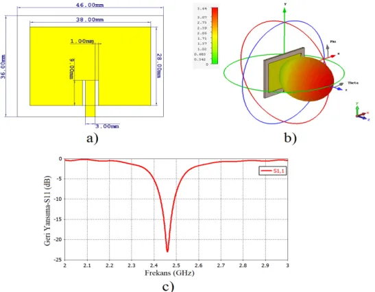
In this study, the microwave imager design was carried out using a commercially available microwave simulation program based on finite integration method. The microstrip patch antennas operating at the 2.46 GHz frequency are designed as microwave imaging elements and are periodically positioned 5x1 into a 24-sided cylinder. A metal layer and dielectric layer was used in antenna design process the dielectric layer was chosen as FR4 with thickness of 1.6 mm and dielectric constants of 4.3 and the copper was used in the antenna and ground layers with thickness of 0.035 mm and conductivity of 5.8x10⁷. The designed unit microstrip antenna is shown in Fig. 1a with size parameters. The microstrip antenna with rectangular patch is making a good orientation with the linear gain of 3.64 dB and the 3D propagation is shown in Fig. 1b. The designed patch has a return loss value of -23 dB at 2.46 GHz, which is the antenna resonance frequency, Fig. 1c. The designed antenna is available in this state.
Figure 1. 2.46 GHz patch antenna a) dimensional parameters, b) 3D radiation graph and c) antenna back reflection value (S11)
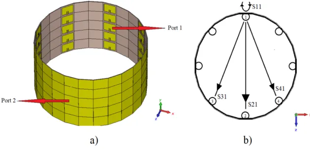
3. Cylindrical Resonator Design by Patch Antennas
The developed microwave imager is based on the transmission values of antennas as mentioned before. If the third layer of the cylindrical microwave imager structure shown in Fig. 2a is taken into account, the interaction between the antennas can be used in imaging process with image algorithm. The scattering parameters S11, S21, S31 and S41 values were calculated according to the configuration shown in Fig. 2b, they have different values for different materials placed in the cavity and when these scatter parameters were obtained for all antennas, three-dimensional mapping can be created with the help of the necessary algorithm.
Figure 2. a) 5x1 patch antenna cavity resonator placed in octagonal b) inner antenna transmission and reflection working mechanism
4. Reflection and Transmission Characteristics of Designed Antennas
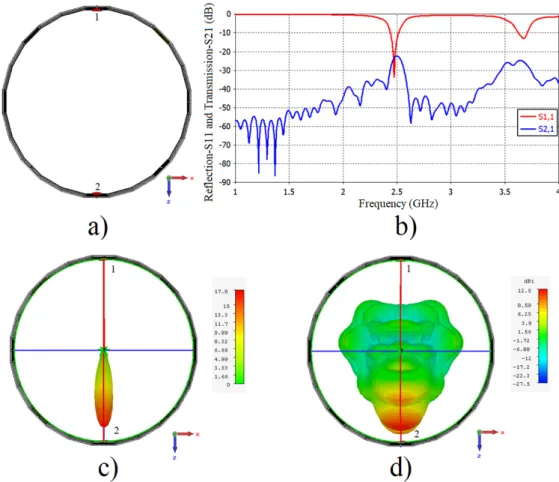
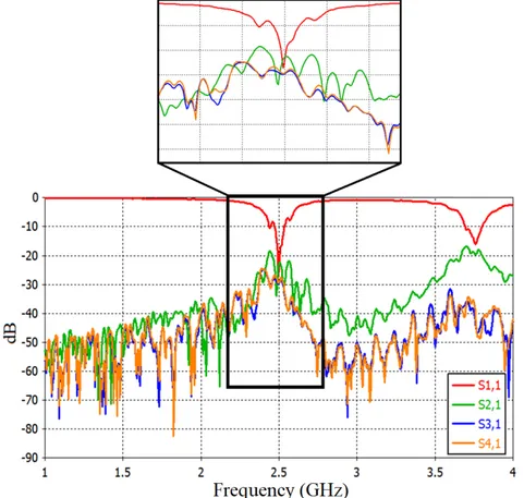
In order to see the differences in the transmission values, the transmission (S21) and the reflection (S11) values between the two opposing antennas were examined. Interactions between eight microstrip patch antennas located at the middle layer and placed at 45˚ angles will form a two-dimensional map. In addition, it is possible to create a three-dimensional image with inner antenna transmission values in the other four layers. Fig. 3a shows a top view of the two opposing antennas; the microwave imager is seen at 2.50 GHz in Fig. 3b, where maximum data transfer is performed when the cavity
state is empty. The frequency of 2.50 GHz is in the resonance band for the antenna and is at the maximum level with the transmission value of -22.35 dB. This value constitutes the maximum reference point for the mapping algorithm. In addition, the propagation values between the antennas are calculated as linear dBi and are given in Fig. 3c-d. According to the obtained 3D propagation patterns, maximum power transfer is among the opposing antennas.
Figure 3. a) in the empty state imager microwave resonator, b) transmission between two opposing ports and backscatter, c) linear radiation of port1, d) dBi radiation of port1
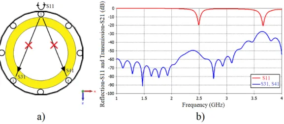
For Port 1, the transmission values for two opposing antennas (3-4) are calculated when the S31 and S41 form the basis of the imaging algorithm and are given in Fig. 4 with the port configurations. As can be seen from the transmission graph, transfers from port1 to port3 and port4 (S31, S41) are at the maximum and -30 dB at 2.46 GHz, which is the resonance frequency. This value can be used in the algorithm for the maximum transmission value to the opposite lateral antennas for the empty cavity state.
Figure 4. Empty cavity structure and cross transmission values
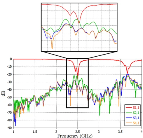
For the mapping process, it is necessary to observe the effect of metal as another reference value. A copper cylinder is placed inside the cavity and its effect on the transmission between antennas is examined. Firstly, the apparatus shown in Fig. 5a is formed and the mutual two-port transfer is examined. Although no major change was observed in the resonance frequency, the S21 value between port1 and port2 experienced a significant decrease compared to the value in the empty cavity state. The reason for the transmission shown in Fig. 5b is the placement of metal in the medium and the transmission value resonant frequency of about 2.50 GHz decreased to -50 dB. Moreover, the transmission values of this metal plate against the two cross opposing antennas also showed a significant decrease and are shown in Fig. 6. As shown in the figure, the values S31 and S41 in the 2.45-2.50 GHz range decreased below -50 dB.
Figure 6. Cross transmission with metal in the empty cavity state
As shown in Fig. 7, the metal effect causes a serious transmission decrease between port1 and port2. In the empty cavity state, the maximum transmission occurs at the resonant frequency and this transmission value is at -23 dB. This situation was reduced to -52 dB level as seen in the figure when the metal was positioned in the cavity. This transmission down values will be used as a scale for the use of the cavity-antenna structure as a microwave imager. In the light of the empty and metallic results obtained, the values which can be found between these 29 dB differences will vary in different dielectric materials.
Figure 7. Transmission values under empty and metallic (copper fill) states
As mentioned in the previous paragraph, the different dielectric constant materials were positioned in the cavity and simulations were conducted in order to change the transmission values in the range between the 2.45-2.50 GHz band with 29 dB difference. Firstly, the dielectric material of Arlon AD 300, which has a dielectric constant (𝜀) 3, was
placed in the cavity. The transmission and reflection results seen in Fig. 8 were obtained for the opposite and opposite-cross antennas. As seen, the material of 𝜀=3 has made a small difference in resonance, but the transmission values have been varied according to the empty situation. It transmits with a maximum transmission value of -22 dB in the resonance band to the opposite antenna. However, a maximum of -28 dB transmission occurs to the two lateral antennas. These values form data for characterizing the designed cavity antenna structure.
Figure 8. Arlon AD 300 (𝜀 = 3) filled to cavity and side ports interaction values
Another simulation was performed using a material whose dielectric constant was different. Gallium Arsenide with a dielectric value of 𝜀 =13 was placed in the cavity and transmission values between antennas were obtained. As shown in Fig. 9, the transmitting antenna which resonates at the 2.50 GHz frequency transmits to the opposite antenna and the opposite lateral antennas at this frequency. In the resonance band the transmission value to the opposite antenna is -23 dB and the transmission value to the opposite cross-lateral antennas is at -28 dB. In order to increase the image capacity of the designed
should be examined in detail. The values obtained for the single layer can be developed by examining the transmission values between each antenna and two dimensional and three dimensional sensitive images can be obtained.
Figure 9. Gallium arsenide (𝜀=13) filled to cavity and side ports interaction values
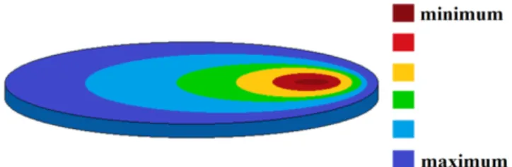
Finally, the approach to the inner space imaging was targeted at the later stages of this simulation study. This approach, which is made on only one layer, is shown in different shades in Fig. 10. The transmission differences in the resonance frequency can be used with the required calculation technique and algorithm during the imaging phase. The image approach shown in the figure represents the mapping of the maximum and minimum transmission values between each antenna. A minimum level of -50 dB represents the point at which transmission is decreased. The maximum point represents the region where the transmission is at -20 dB. Such an approach demonstrates the usability of the designed array antenna cavity structure in microwave imaging applications. The designed structure has advantages such as easy design and production, low cost and high imaging quality. It could be used in medical imaging, non-destructive imaging and mapping applications.
Figure 10. Image approach for single layer 5. Conclusion
In this simulation study, microwave imager design was performed using a series of patch antennas. The designed unit microstrip patch antenna resonates at the 2.46 GHz central frequency. The microwave imager with 24 edges consists of 5x1 patch antenna arrays placed at 45˚ angles. The main operating principle of the imager is based on a total of 40 antenna interconnected transmission values according to antenna positions. The changes in the transmission values have been examined and tested by different materials. At the resonance frequency, the transmission value between the two antennas increases to a maximum of -20 dB and in addition, the transmission value between the opposite lateral antennas is also at these levels. In the case where the cavity is filled with metal, the transmission between the antennas placed in the opposite face is below the level of -50 dB. In addition, the dielectric constant in the cavity was filled with materials that are different. The obtained results show that the designed cavity structure can be used for microwave imaging applications. By creating the necessary algorithm, each antenna transmission values will allow mapping of the inner space. In this study, the image approach for the single layer was performed and was colored based on the maximum-minimum transmission values. The designed microstrip antenna gap structure can be used in medical such as tumor detection, mapping and non-destructive imaging applications.
References
[1] Paulsen, K.D., Meaney, P.M., Nonactive antenna compensation for fixed-array
microwave imaging-Part I: Model development, IEEE Transactions on Medical Imaging,
18(6), 496-507, 1999.
[2] Meaney, P.M., Paulsen, K.D., Chang, J.T., Fanning, M.W., Hartov, A.,
Nonactive antenna compensation for fixed-array microwave imaging: Part II-Imaging results, IEEE Transactions on Medical Imaging, 18(6), 508-518, 1999.
cancer detection, IEEE Microwave and Wireless Components Letters, 11(3), 130-132,
2001.
[4] Fear, E.C., Li, X., Hagness, S.C., Stuchly, M.A., Confocal microwave imaging
for breast cancer detection: Localization of tumors in three dimensions, IEEE
Transactions on Biomedical Engineering, 49(8), 812-822, 2002.
[5] Fear, E.C., Sill, J., Stuchly, M.A., Experimental feasibility study of confocal
microwave imaging for breast tumor detection, IEEE Transactions on Microwave Theory
and Techniques, 51(3), 887-892, 2003.
[6] Xie, Y., Guo, B., Xu, L., Li, J., Stoica, P., Multistatic adaptive microwave
imaging for early breast cancer detection, IEEE Transactions on Biomedical
Engineering, 53(8), 1647-1657, 2006.
[7] Nilavalan, R., Craddock, I.J., Preece, A., Leendertz, J., Benjamin, R., Wideband
microstrip patch antenna design for breast cancer tumour detection, IET Microwaves,
Antennas & Propagation, 1(2), 277-281, 2007.
[8] Chen, X., Liang, J., Wang, S., Wang, Z., Parini, C., Small ultra wideband
antennas for medical imaging, Loughborough Antennas and Propagation Conference,
Loughborough, UK, 28-31, 2008.
[9] Stang, J.P., Joines, W.T., Tapered microstrip patch antenna array for
microwave breast imaging, IEEE MTT-S International Microwave Symposium Digest,
Atlanta, GA, USA, 1313-1316, 2008.
[10] Klemm, M., Craddock, I.J., Preece, A., Leendertz, J., Benjamin, R., Evaluation
of a hemi- spherical wideband antenna array for breast cancer imaging, Radio Science,
43(6), 1-15, 2008.
[11] Yang, B., Yarovoy, A.G., Ligthart, L.P., UWB stacked patch antenna design
for near-field imaging radar antenna array, 3rd European Conference on Antennas and
Propagation, Berlin, Germany, 817-821, 2009.
[12] Amineh, R. K., Trehan, A., Nikolova, N.K., TEM horn antenna for ultra-wide
band microwave breast imaging, Progress in Electromagnetics Research B, 13, 59-74,
2009.
[13] Bourqui, J., Okoniewski, M., Fear, E.C., Balanced antipodal Vivaldi antenna
with dielectric director for near-field microwave imaging, IEEE Transactions on
Antennas and Propagation, 58(7), 2318-2326, 2010.
[14] Al-Joumayly, M.A., Aguilar, S.M., Behdad, N., Hagness, S.C., Dual-band
miniaturized patch antennas for microwave breast imaging, IEEE Antennas and Wireless
Propagation Letters, 9, 268-271, 2010.
[15] Aguilar, S.M., Al-Joumayly, M.A., Burfeindt, M.J., Behdad, N., Hagness, S. C., Multiband miniaturized patch antennas for a compact, shielded microwave breast
imaging array, IEEE transactions on antennas and propagation, 62(3), 1221-1231, 2014.
[16] Biswas, B., Ghatak, R., Poddar, D.R., A fern fractal leaf inspired wideband
antipodal vivaldi antenna for microwave imaging system, IEEE Transactions on
Antennas and Propagation, 65(11), 6126-6129, 2017.
için bir düzlemsel dikdörtgen monopol anten tasarımı ve optimizasyonu, DÜMF
Mühendislik Dergisi, 9(1), 1-12, 2018.
[18] Wang, F., Arslan, T., A thin-film-based wearable antenna array for breast
microwave imaging and diagnosis, First IEEE MTT-S International Microwave Bio
Conference (IMBIOC), Gothenburg, Sweden, 1-4, 2017.
[19] Rokunuzzaman, M., Samsuzzaman, M., Islam, M.T., Unidirectional wideband
3-D antenna for human head-imaging application, IEEE Antennas and Wireless
Propagation Letters, 16, 169-172, 2017.
[20] Zamani, A., Rezaeieh, S.A., Bialkowski, K.S., Abbosh, A.M., Boundary
estimation of imaged object in microwave medical imaging using antenna resonant frequency shift, IEEE Transactions on Antennas and Propagation, 66(2), 927-936, 2018.
[21] Alkurt, F.O., Altintas, O., Atci, A., Bakir, M., Unal, E., Akgol, O., Delihacioglu, K., Karaaslan, M., Sabah, C., Antenna-based microwave absorber for
imaging in the frequencies of 1.8, 2.45, and 5.8 GHz, Optical Engineering, 57(11),
113102, 2018.
[22] Zhou, T., Zhu, A., Shen, Y., Li, H., Li, C., Hangfu, J., Single frequency
microwave imaging based on compressed sensing, IEEE Radio and Wireless Symposium