18 January 1999
PHYSICS LETTERS A
ELSEZVIER Physics Letters A 251 ( 1999) 169- I76
A chaotic masking scheme
by using synchronized chaotic systems
dmer Morgiil a,l, Moez Feki b-2
Received 23 February 1998; revised manuscript received 30 June 1998; accepted for publication 9 November 1998 Communicated by A.P. Fordy
Abstract
We present a new chaotic masking scheme by using synchronized chaotic systems. In this method, synchronization and message transmission phases are separated, and while synchronization is achieved in the synchronization phases, the message is only sent in message transmission phases. We show that if synchronization is achieved exponentially fast, then under certain conditions any message of any length could be transmitted and successfully recovered provided that the synchronization length is sufficiently long. We also show that the proposed scheme is robust with respect to noise and parameter mismatch under some mild conditions. @ 1999 Published by Elsevier Science B.V.
PAC.9 054S.+b
Kqwtrd~t Chaotic systems; Chaos sync~onization; Chaotic masking; Lorenz system
1. Introduction
In recent years the idea of synchronization of chaotic systems has received a great deal of interest among scientists from various fields, see e.g. [ I-14]. One of the motivations for synchronization is the pos- sibility of sending messages through chaotic systems for secure communication, see e.g. Refs. [5,7,9]. Such synchronized systems usually consist of two parts: a generator of chaotic signals (drive system}, and a receiver (response system). The response sys- tem is usually a duplicate of a part (or the whole) of the drive system. A chaotic signal generated by the drive system may be used as an input in the response
’ E-mail: [email protected]. ? E-mail: [email protected].
system to synchronize the common signals of both systems, see e.g. Ref. [ 21. After synchronization, one may add the message to the chaotic signal used for synchronization and send this signal to the receiver. This is called chaotic masking, see Ref. [ 8 f . and un- der certain conditions one may recover the message from the signals of the response system, see e.g. Ref.
[91.
Recently, a new synchronization scheme based on occasional coupling has been proposed in Ref. [ I I]. This scheme, as others proposed in the literature, has a potential application for secure communications. In this Letter we propose a chaotic masking scheme based on the occasiona synchronization proposed in Ref. [ 1 I] and present some simulation results concerning the message transmission.
A related scheme for synchronization of chaotic sys-
037%9601/99/$ - see front matter @ 1999 Published by Elsevier Science B.V. All rights reserved. PI! SO375-9601 f 98 )00868-S
170 6. Morgiii. M. Feki/Phwics Letters A 251 (1999) 169-176 terns was proposed in Ref. [ 121. In this scheme, the
synchronization signal is used in the response system at discrete times. For a finite time step r > 0, response system states corresponding to the drive variables used in the synchronization signal are set to the values of corresponding drive variables at instances f = 127, II = 1.2, . . ., and it was shown that for r sufficiently small, synchronization is possible. Hence, the synchroniza- tion signal is used only at certain instances in Ref.
[ 121, whereas it is used in an interval in our scheme. We note that the length of this interval is of crucial importance in our analysis, see Section 2. As a result, some of the response system states are instantaneously set to the values of corresponding drive system states in Ref. [ 121, whereas both system states asymptoti- cally approach to each other in our scheme, see also Ref. [ 1 11. Both schemes use an interval in which the response system is autonomous, and the scheme of Ref. [ 121 may be related to our scheme in which the switching signal is impulsive, see Remark 2.
This Letter is organized as follows. In Section 2 we introduce our message transmission scheme, show that under some mild conditions successful message recovery is possible and that the scheme is robust with respect to noise and parameter mismatch. In Section 3 we present some simulation results. Finally, we give some concluding remarks.
2. Occasional coupling
Let the chaotic master system be given by the fol- lowing equation.
li=f(u,p) 1 (1)
where u E EX” is the state of the master system, p E R” is a parameter vector, and f : IbY x IRf’ -+ KY is a smooth function. We assume that for certain values of ,x, the solutions of ( 1) exhibit chaotic behaviour. A certain function of u is assumed to be measurable and is sent to the slave system for synchronization. For simplicity, let us assume that this synchronization signal is given as o = cTu where c E lP is a constant vector, and the superscript T denotes the transpose. The slave system may be chosen as follows,
ti=f(w,&+S(t)K(W)(O-cTW), (2)
where w E ll?’ is the state of the slave system, s(t) = 0, 1 denotes the switching signal, and K : Et” -+ IR” is the feedback gain vector. We assume that K is a smooth function of w. This form indicates that when s(t) = 0 (i.e., the switch is off), the slave system is a duplicate of the master system. We assume that when s(t) = 1 (i.e., the switch is on), the gain vector K(w) could be chosen so that the synchronization error e ( I) = u ( t ) - w ( t ) decays exponentially to zero, that is there exist some M 3 1, (Y > 0 such that for any to 3 0, e( to) E IF!“, the following holds,
ile(l)ll 6 Me-acf-‘“)ile(ta)II, f 3 to, (3)
where 11. II denotes the standard Euclidean norm in KY. We note that in some cases (3) may hold only locally, i.e. for []e( to) ]I 6 r for some Y > 0, in which case we say that the synchronization holds only locally.
We note that under certain conditions such a gain vector could be found in a systematic way, and that most of the synchronization schemes proposed in the literature satisfy this assumption, see Ref. [ 141. The synchronization scheme given by (2) is similar to the observer based synchronization proposed in Refs. [ 13,141. In this scheme we assume that the system given by ( 1) is in the following form,
li = f(u> P) = A(P)u + g(u, pu) , (4) where for each ,u E Iwp, A E IPx”, is a constant matrix and g( .) : R” --f Et” is a smooth function. By using (2)) (4) and assuming that K is a constant vector, we obtain the following error dynamics in the coupling phase (i.e., when s(t) = I),
P = (A(p) - KcT)e + g(u,p) - g(w,p) , (5) where we used o = cTu. If, for a fixed p, the pair (A, c) is observable then there exists a constant gain matrix K E LR” such that A, = A - KcT is stable, see Refs. [ 13,141. Moreover, assume that g( .) is Lipschitz, i.e., the following holds,
lIg(u* P) - g(w, P)
II 6 kllu - 4 1
L&WEIR”, p. E w , (6)
for some k > 0 in a region 0 C IV x IP in which the solutions are bounded. If k > 0 is sufficiently small, then the synchronization error e decays exponentially
0. Morgiil, hf. Feki/Physics Letten A 251 (1999) 169-176 171
to zero, i.e. (3) holds; if k is not smaIl but
Aand g(a)
are in some special form, then (3) still holds for a
particular choice of K, see Refs.
[13,14 1. In any case,
if lie(te) jj is sufficiently small, we may expect (3) to
hold. We note that in this paper we assume that the
feedback gain K may be a function of w, whereas it
is assumed to be constant in Refs. [ 13,14 1.
Remark 1.
TQ emphasize the consequences of as-
sumption (3), let us consider the “error system” in
terms of the error e. By using (
1)and (2), one can
obtain the error dynamics, and (3) implies that e = 0
is an exponentially stable equilibrium point of the
error system. Since the exponentially stable systems
are robust with respect to small changes in the system
dynamics, see Ref. [ 151,
weexpect that the message
transmission technique which wiIl be given below is
robust with respect to noise and parameter mismatch.
This point was proven in Refs. [ i 1,13,14]. We also
note that for most of the synchronization techniques
proposed in the literature the exponential synchroniza-
tion property given by (3) is satisfied. By using this
fact one can prove the robustness of these techniques
with respect to noise and parameter mismatch.
Our chaotic masking scheme by using the occa-
sional couphng proposed in Ref. {l I] is based on
changing the switching signal s(t) between 0 and 1,
peri~ical~y. More precisely, let m(t) denote the mes-
sage to be transmitted, let T, > 0 and
Tm > 0denote
the intervals for synchronization and message trans-
mission phases, respectively. Then, for j = 1,2,.
. .,our scheme is as follows:
(i) m (jth synchronization phase) For (j- 1) (TV+
7;,,) <
t < j;i-, f (j -l)T,, use the master system
given by (
I )and the slave system given by (2)) with
s(r) = 1.
(ii) (jth message transmission phase) For
JT$ + (j -1)
TV, < t < j( T, 4 T,),use the master system
given by ( 1) and the sIave system given by (2), with
s(t) = 0, and send the masked message y(t) + m(r).
(iii) (message recovery) In the jth message trans-
mission phase, the recovered message
m,(t)can be
computed as
m,(r) =0(t) +m(t)
-cTw(l).
(7)
Note that with s(t) = 0, the response system given
(2) becomes an autonomous system in the message
transmission phase. Since in the synchronization
phase, the error decays to zero exponentially fast
(see (3)), at the end of this phase the error becomes
extremeIy small, provided that
Tsis sufficiently large.
Hence, for the message ~ansmission phase we could
exchange the signals of the drive system used for
synchronization with the corresponding signals of the
response system, which is the rationale behind using
s(t) = 0 in (2). We have the following result for the
message transmission.
T~e~rern 1.
Consider the systems given by (
I ), (2)and the message transmission scheme given above.
Assume that f(u, CL) is Lipschitz in U, i.e. satisfies
an inequality similar to (6) with a Lipschitz bound
k,,,
and that (3) holds. Let the initial error satisfy
\le(O)II < r for some r > 0, and let (the precision
number) E > 0 be given. Then, for any message of
length
T,, > 0,there exists a synchronization interval
T, > 0
such that in the message transmission phase
we have
llmr(O -
m(t)
II
-G
E f(8)
where j7;. + (j -
i)T,, G t < j(‘& + T,,g),and j =
1,2,....
Prc.x$
For simplicity, we define the beginning of jth
synchronization and message transmission phases T;
and
Tr,respectively, as follows,
T;=(j-l)(T~+Tr,,), v’=jT,+(j- l)T,,,,
j= 1,2,... . (9)
From (3) it is clear that the following holds in the jth
synchronization phase,
]]e(t)J] 6
Me-“+r;)(]e(~))/ ,Tf < t <
ri”’ .
(10)From ( 1) and (2) it follows that the following holds
in the jth message ~ansmission phase,
r_
Ty < t < rj”+, . (11)
By using Lipschitz inequality, taking norms and using
the Bellman-~ronwall lemma, we obtain
lle( t) jj < ek”“-T~)Ile(T~)“)IJ , T!” < t < T!
.I ’ ./+I .
(12)
By using ( 12) and ( i0) successively, and noting that the error is continuous, we obtain
//“r(r) - @r(g)ll = llcTe(t)ll < ~lc~l~l~(~~~~ * (14) see (7). It follows from ( 13) and ( 14) that (8) holds if the following is satisfied for all j,
j= 1,2,... . (I.51
If lnE/r]Jc]] < 0, then (IS) is satisfied provided that the following holds,
In M + k,T,,, - aT, < In -?-
+-Ii
. (16)On the other hand, if lnE/r\]c/] 2 0, then (15) is satisfied provided that the following holds,
In N + k,,T,,? - ~4 6 0. f 17)
Once T,, > 0 is selected arbitrarily, the required 7; > 0 could be found from ( 16) or ( 17). cl
The result stated in Theorem 1 hoIds in the ideal case when the signal transmitted (i.e., 5) is not cor- rupted by noise and when the parameter vectors (i.e., p) are the same in the drive and the response sys- tems. In the sequel we consider the nonideal case and prove that the scheme given above is robust with re- spect to noise and parameter mismatch under certain conditions. First note that in the nonideal case, the re- sponse system given by (2) should be replaced with the following,
tit= ,f(w,&) + s(t)K(KJ)(o+n -
crw>
,
(18) where y’ is the parameter vector for the response sys- tem, and IZ is a (random) noise term in the measure- ments. Then we have the following robustness result.Theorem 2. Consider the drive and response systems given by ( 1) and ( 18)) respectively. Assume that the solutions remain in a bounded set. Assume that f( U, ,u) is Lipschitz in both variables. Let the noise n satisfy /ln( t) 11 6 IZ,, for some nn, > 0 for t 2 0 and let us define A@ = ,u - pt. Then in the synchronization phases (i.e., for s(t) = I), the error asymptotically (i.e., as t ---+ M) satisfies the following inequality,
Ildt)li G Cln,, + GllA~ll 7
(19)where Ci > 0 and CZ > 0 are some constants.
Proo$ Since the solutions remain in a bounded set, llK( w) // remain bounded in this set as well. Hence we have
where kl = max{ I/ K( w) II}. Then the proof follows from the exponential stability assumption (3) and the
Theorem 2 of Ref. [ I 11. q
Theorem 2 proves that in the presence of noise and/or parameter mismatch, the synchronization error remains bounded, hence the proposed scheme is ro- bust in the nonideal case. Moreover, the error bound is linear in noise and parameter mismatch bounds; hence as these bounds decrease, the synchronization error bound also decreases. Also note that here we have an asymptotic result, i.e. (19) hoids as t --+ cm. From practical point of view we may assume that ( 19) holds if T, is suf~ciently large. We note that the conclusions of Theorem 2 remains true if c’ # c is used in f 18), provided that a term Csllc -- c’J/ is added to ( 19).
Theorem 3. Consider the drive and response systems given by ( I) and ( 18), respectively, and let s(t) = 0 (i.e., in message transmission phase). Assume that f(u, h) is Lipschitz in both variables. Assume that T, is sufficiently large so that ( 19) is satisfied. Let E > 0 be a
given precision level which satisfies
Ilcll(C~&, + C~lbIl)
< f.
(20)
Then there exists a maximum allowable message trans- mission interval T > 0 such that for Tnl 6 T, (8) holds.
0. Morgiil, M. Feki/Physics Letters A 251 (1999) 169-176 173
Proof: The proof follows from the analysis presented
in Ref. [ 111. a
We note that some other factors such as finite reso- lution of simulations or experiments (e.g., A/D con- verters) may also contribute to the error bound given above, hence may affect T,,.
Remark 2. In Ref. [ 121, an occasional synchro- nization scheme based on impulsive coupling was proposed. More precisely, let the given chaotic sys- tem is = f(u) be decomposed as lit = ft (~1, UZ), it2 = ~~(u,,EQ). Let T > 0 be given and use a similar response system, i.e. 11, = fi(~t~,zl~~), tilr = ~~(u,~,uz~). Assume that u,,(O) = Q(O), and
U2r(O) = u2 (0) + 6, where 6 is sufficiently small.
For t = nr,n = 1,2,. . .) set externally urr(127) = tlr (nr), and for r # nr, use the response system given above. It was shown in Ref. [ 121 that for r > 0 sufficiently small, synchronization is possi- ble. To see that the coupling is impulsive, we write lilr = ft(~r~,~z~) + s(t)(~r - ~1~) where s(t) = c,“, S( I - rz~), and S( .) is the Dirac delta function. If we formally integrate this equation in [rzr-, nr+] , we obtain (formally) t-lt,(n~+) = ui (nr). We note that in our scheme the switching signal is a square wave which is drastically different from an impulse, and we do not make any assumptions on initial con- ditions. Consequently, the results presented in Ref. ] IZ] and here cannot be deduced from each other. Moreover, the length of the synchronization interval TV > 0 is of crucial importance for our scheme, and our results do not hold for T,. = 0, see ( 16), ( 17). Also note that when s(t) = 1, i.e. a unit step, our scheme for synchronization is the same as the scheme in Refs. [ 8,9].
3. Simulation results
For an application of the ideas given above, we con- sider the well-known Lorenz system for the drive sys- tem, see Ref. [ 21. Since the state variables of Lorenz equations may vary in a wide dynamical range, for simulation purposes following Ref. [ 81, we use the following “scaled” Lorenz system,
k = a(y - X) ,
$= -20xz +rx-y,
i = 5x-y - bz .
(21)
We choose the parameters (+, r and b so that the Lorenz system (21) is in the chaotic regime. The solution X(
t
) of (2 1) will be used to synchronize the solutions of the following response system, see Ref. [ 81,xr = dy, - &> ,
jr== -2Ox,z,+rx,-_y,+s(t)(-202,+r)(x-x,),
t, = Sx,y, - bzr + Ss(t)y,(x - n,) . (22) In our notation we have u = (X y z)~, w =
(x, y,. z,.)~, o = X, hence we have c = (1 0 O)T. Note that (22) is of the form (2) with K(w) = (0 - 202, + r 5yr)T. Moreover, when s(t) = 1, (22) becomes
jr = -2Oxz, + rx - yr ,
i, = Sxyr - bz, t (23)
which is the response system used in Refs. [ 2,8]. By using a suitable Lyapunov function, it could be shown that (21) and (22) synchronize exponentially fast, i.e.
(3) ho1dsseee.g. Refs. [11,13,14].
For longer messages we could choose the synchro- nization interval rY su~ciently long so that the error made in the signal recovery is arbitrarily small. Al- ternatively, we could divide the message into smaller parts, if possible, and send each part in a message transmission phase, followed by a synchronization phase.
Next we present some numerical simulation results which indicate that the suggested method can be used for successful message transmission and recovery. In the first two simulations, we considered the ideal case (i.e., no noise and no parameter mismatch). In the first simulation, as the message to be sent, we used the speech signals corresponding to the sounds of let- ters “A” and “B”. This message is obtained by using the sound tools available in Sun Sparcstations. In this simulation, we use v = 10, r = 20, b = 1, T, = 15 sec. and T,, = 20 sec. This message is recovered with good listening quality. The simuIation results can be seen in Fig. 1. In the second simulation, the message to be
174 6. Morgiil, M. Feki/Physics Letters A 251 (1999) 169-176
tme
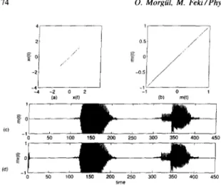
Fig. I. Transmission of sounds “A” and ‘3” was received with perfect listening quality. (a) Drive versus response signals; (b) transmitted versus recovered messages (data was plotted after transient time); (c) transmitted message versus time; (d) received message versus time.
sent is the coded version of the word “chaos”. For cod- ing, we used the standard international alphabet code no. 2, see e.g. Ref. [ 161. As it is seen in Fig. 2, mes- sage recovery is very successful. In this experiment, we choose u = 16, r = 46, b = 4, T, = 10 sec. and T,,, = 10 sec. In both simulations, message amplitude is not small as compared to that of the drive signal. The message level is not important in this case, with arbitrary message levels one can recover the message successfully. In Fig. 2d, the signal transmitted to the receiver is also plotted. As can be seen, although the message level is comparable to that of the chaotic car- rier, it is well masked, and the switching instances are not detectable. Most of the message transmission techniques proposed in the literature require that the message level be sufficiently smaller than the chaotic signal level, and this may be a problem when noise is also present, since then the message level should also be sufficiently bigger than the noise level for success- ful message recovery. Our aim in these simulations is to show that even if the message level is comparable with the chaotic signals, one can still recover the mes- sage successfully in our scheme.
In the remaining simulations we considered the non- ideal case. For the noise, we used Gaussian noise with zero mean (and scaled magnitude), generated by com- puter. In the third simulation, we considered the trans- mission of the sentence “wish you good luck” in the nonideal case. This sentence is coded by using the
Fig. 2. (a) Transmitted message; (b) recovered message; (c) error in message recovery; (d) signal transmitted to the receiver. same code used above. To show the arbitrariness of the message level, this time we chose the maximum mes- sage level as 0.05 and we considered both noise and parameter mismatch. Since in this case we could not send arbitrarily long messages in our scheme, we di- vided the message into four parts, and sent each word in one message transmission interval, which is then followed by another synchronization interval. We use g = 10, r = 20, b = 1, T, = 25 sec., T,, = 30 sec. for the following simulations. For the noise amplitude and the parameter mismatch, we considered two cases. In the first case, noise amplitude is scaled to 10h5 and all parameters are changed by 0.02% in the response system (i.e., multiplied by 1.0002). The results are given in Figs. 3a,d. As can be seen, the message is re- covered successfully. In the second case, noise ampli- tude is scaled to 10m3 and all parameters are changed by 0.2% in the response system. The results are given in Figs. 3b,e. We also performed various simulations with bigger noise and parameter mismatch values. Ac- cording to these simulations, as those values become bigger, we could still recover the message with suf- ficient accuracy by increasing T, and decreasing T,,,. Obviously, the message level should be sufficiently bigger than the noise level.
4. Conclusion
In this paper we considered a chaotic masking scheme by using synchronized chaotic systems. As in
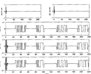
Fig. 3. (a) Error in message recovery
for case
1 (n,, =lo-“.
p = 0.02%
parameter mismatch); (b) error in message recovery for case 2 (n, = IO-‘, p = 0.02%); (c) transmitted message; (d) recovered message for case I; (e) recovered message for case 2.most synchronization schemes, we assume that a drive
system generates chaotic signals and some of these
signals are used in the response system for synchro-
nization. In our scheme, communication is divided
into synchronization and message transmission inter-
vals, and while the drive and the response systems are
only synchronized in the synchronization interval, the
message is only sent and recovered in the message
transmission interval. In the latter interval, the re-
sponse system is switched to an autonomous system,
and we showed that under certain conditions one can
recover the message successfully. We note that the
proposed technique is quite general and could be used
with any synchronized chaotic system, as long as the
stated assumptions hold. We presented some theoreti-
cal and simulation results indicating that the proposed
technique may be used in some applications.
We did not investigate the security of our scheme.
In Ref.
[171, the security of communication schemes
based on chaotic carriers when the hidden information
signal is buried at the order of -30 dB with respect to
the chaotic carrier were analyzed and it was concluded
that such systems may be useful to increase privacy,
but may not provide a high level of security. It was
also concluded in Ref. [ 171 that the hidden signals
added to the chaotic carrier at low power make it even
easier to recover the hidden signal. We do not claim
any level of security for our scheme, and probably the
conclusions of Ref. [ 171 apply to our scheme as well
when the message level is low. But we note that our
results are independent of the message level, whereas
in most of the chaotic masking schemes the message
level is required to be sufficiently lower than that of
the chaotic carrier. In view of the results of Ref.
[171,
the flexibility in adjusting the message level might
improve the security of our scheme. However, this
point requires further research.
We also did not consider the problem of synchro-
nization of the switching signal s(t) between the drive
and the response systems. Since s(t) is a periodic sig-
nal, oscillators which generate the same s(t) could be
built, tuned and used at transmitter and receiver. Such
oscillators could be triggered by a signal transmit-
ted through the data channel prior to communication,
preferably several periods before the actual transmis-
sion. Other schemes may also be possible, but since
this is not our main aim, we do not discuss this prob-
lem in detail here.
Several improvements on the scheme proposed in
this paper are possible. The estimate given by ( 15)
appears to be very conservative. Instead of using the
Lipschitz constant k, in ( 15), one might use an ap-
propriate Lyapunov exponent associated with the drive
system, cf. ( lo), ( 12). Then, by choosing the param-
eters (i.e., cr,
b, r)appropriately, one might obtain
small positive Lyapunov exponents. This may affect
the maximum message transmission interval r,,,. We
expect that as the positive Lyapunov exponents be-
come smaller,
Tmbecomes larger. An optimum relation
between Ts and 7’, may also be obtained. The relations
between the Lyapunov exponents, intervals T,,
T,,and
the security level of our scheme should also be ana-
lyzed. An electronic circuit implementation may also
be possible, see Ref. [8]. Work along these lines is in
progress and the results will be presented elsewhere.
References
[I] L.M. Pecora, T.L. CarroIl, Phys. Rev. Lett. 64 (1990) 821. [ 21 L.M. Pecora, T.L. CarroIi, Phys. Rev. A 44 ( 1991) 2374. [ 31 L.O. Chua, L. Kocarev, K. Eckert. Int. J. Bifurcation Chaos
2 (1992) 705.
[41 M.J. Ogorzalek, IEEE Trans. Circuits Syst. 40 ( 1993) 693. [S] L. Kocarev, K.S. Halle, K. Eckert, L.O. Chua, Int. J.
Bifurcation Chaos 2 (1992) 709.
[6] C.W. Wu, L.O. Chua, hit. J. Bifurcation Chaos 3 (1993) 1619.
176 6. Mor@l, M. Feki/Physics Letters A 251 (1999) 169-I 76 [7 1 K.S. HalIe, C.W. Wu, M. Itoh, L.O. Chua, Int. J. Bifurcation
Chaos 3 ( 1993) 469.
18) K.M. Cuomo, A.V. Oppenheim, Phys. Rev. Lett. 71 (1993) 65.
[ 91 K.M. Cuomo, A.V. Oppenheim, S.H. Strogatz. IEEE Trans. Circuits Syst. 40 (1993) 626.
/ 101 L. Kocarev. U. Pa&z, Phys. Rev. Lett. 74 ( 1995) 5028. 1 I I] 8. Morgiil, M. Feki, Phys. Rev. E 55 ( 1997) 5004. [ 121 R.E. Amritkar, N. Gupte, Phys. Rev. E 47 (1993) 3889.
[ 131 6. MorgiJl, E. Solak. Phys. Rev. E 54 (1996) 4803. [ 141 6. Morgtil, E. Solak. Int. J. Bifurcation Chaos 7 (1997)
1307.
1 15 1 H.K. Khalil, Nonlinear Systems (Macmillan, New York. 1992) pp. 180-208.
[ 161 W.D. Gegg, Analog and Digital Communication (Wiley, New York, 1977) p. 526.