A CLASSIFICATION MATRIX PROPOSAL FOR
DIGITAL FABRICATION TECHNIQUES IN
ARCHITECTURE
A THESIS SUBMITTED TO
THE GRADUATE SCHOOL OF ENGINEERING AND SCIENCE OF BILKENT UNIVERSITY
IN THE PARTIAL FULFILLMENT OF THE REQUIREMENTS FOR THE DEGREE OF MASTER SCIENCE IN ARCHITECTURE By Selen Öztürk November 2018
ii
A CLASSIFICATION MATRIX PROPOSAL FOR DIGITAL
FABRICATION TECHNIQUES IN ARCHITECTURE
By Selen Öztürk November 2018
We certify that we have read this thesis and that in our opinion it is fully adequate, in scope and in quality, as a thesis for the degree of Master of Science.
______________________________________________ Burcu Şenyapılı Özcan (Advisor)
______________________________________________ Assist. Prof. Dr. Aysu Berk
______________________________________________ Assist. Prof. Dr. Gökhan Kınayoğlu
Approved for the Graduate School of Engineering and Science:
______________________________________________________ Ezhan Karaşan
iii
ABSTRACT
A CLASSIFICATION MATRIX PROPOSAL FOR DIGITAL
FABRICATION TECHNIQUES IN ARCHITECTURE
Selen Öztürk M.S. in Architecture Advisor: Burcu Şenyapılı Özcan
November 2018
This thesis investigates the relationship between digital fabrication techniques and the design constraints, such as function and materials, which are determined during architectural design processes by architects. This relationship is formulated through a matrix. Digital fabrication techniques are generally discussed upon and decided at the last step of a design process. This study roots from the idea that knowing which technique to use for fabrication affects the design process. In that sense, ‘according to which constraints which technique suits the design intention best’ should aid the designers. To propose a classification matrix two steps are practiced: first, as digital fabrication is a newly developing area, there are confusions, shifts, and overlaps of terminology among fabrication techniques; thus a simplification and classification in the terminology is needed. Such a classification is carried out in this thesis through recurrence tables based on a literature survey, the output of which constitutes the main column of the matrix. Secondly, a set of design constraints are determined by analyzing built projects, which are realized using specific digital fabrication techniques. This set of constraints establishes the columns of the matrix. The classification matrix aims to contribute both to educational and practical sides of architecture, proposing digital fabrication techniques to designers according to specific design constraints.
Keywords: Digital Fabrication, Digital Fabrication Techniques in Architecture, Architectural Design Process, Computer Aided Design – Computer Aided Manufacturing (CAD – CAM), Computational Design
iv
ÖZET
MİMARİ TASARIMDA DİJİTAL FABRİKASYON TEKNİKLERİNİN
KULLANIMI ÜZERİNE BİR MATRİS ÖNERİSİ
Selen Öztürk Mimarlık, Yüksek Lisans
Tez Danışmanı: Burcu Şenyapılı Özcan Kasım 2018
Çalışmada mimarlıkta kullanılan dijital fabrikasyon teknikleri ve tasarım sürecinde işlev ve malzeme gibi ele alınan kriterler arasındaki ilişki araştırılıp, bu ilişki bir matris yoluyla formüle edilmiştir. Dijital fabrikasyon, tasarım sürecinin son aşamasında değerlendirilmesi gereken bir karar olarak düşünülmektedir. Bu durumun aksine, yapılan çalışmada hangi fabrikasyon tekniğinin tasarıma uygulanacağının önceden bilinmesinin tasarım sürecine de etkisi olduğu savunulmaktadır. Bu bağlamda hangi kıstasın hangi tasarım niyetine uygun olacağını bilmenin tasarımcıyı süreçte besleyen bir durum olduğu vurgulanmaktadır. Matrisi oluşturabilmek için iki aşamalı bir çalışma uygulanmıştır. Dijital fabrikasyon yeni gelişmekte olan bir alan olduğu için terminolojide kavram karmaşası mevcuttur. Bu nedenle ilk önce terminolojide bir sadeleştirme ve sınıflandırma yapılmıştır. Literatür taraması ve tekrar tabloları oluşturularak teknikler sınıflandırılmıştır. İlk adım sonucunda ortaya çıkan teknikler, matrisin ana kolonunu oluşturmaktadır. Matrisin ana kolonunda yer alan dijital fabrikasyon teknikleri sırasıyla kesit alma, konturlama, mozaikleme, katlama ve biçimlendirmedir. İzlenen ikinci adım ise tasarım kriterlerinin belirlenmesidir. Bu kriterler her bir tekniğe özgü uygulanmış tasarımlar analiz edilerek ortaya çıkarılmıştır. Oluşturulan matrisin hem eğitim hem de uygulama alanlarında kullanılması amaçlanmıştır. Çalışmanın sonucunda amaç; tasarımcılara, tasarım sürecinde belirli tasarım kararları için belirli dijital fabrikasyon teknikleri önerisi yapabilecek bir matris oluşturmaktır.
Anahtar sözcükler: Dijital Fabrikasyon, Mimarlıkta Dijital Fabrikasyon Teknikleri, Mimarlıkta Tasarım Süreci, Bilgisayar Destekli Tasarım – Bilgisayar Destekli Üretim (CAD – CAM), Hesaplamalı Tasarım
v
ACKNOWLEDGEMENT
First of all, I want to thank to my supervisor Assoc. Prof. Burcu Şenyapılı Özcan for her guidance and encouragement throughout the thesis process. Experiencing such a process with her advices was valuable not only for this thesis, but also for future academic studies.
Secondly, I would like to emphasize my special thanks and appreciation to all other professors in Bilkent University Architecture Department for their insightful comments during midterm thesis presentations.
Additionally, I owe my deepest gratitude to my parents for their love and continuous support during this process. Nehir, my dearest, your smile gave me strength to go on. Last, but not least, on the contrary the most; to you Recep Can,
Thank you for being beside me in this process: every time with all your encouragement and trust.
vi
CONTENTS
1 INTRODUCTION ... 12
1.1 Problem Statement ... 13
1.2 Aim and Scope of the Thesis ... 13
1.3 Structure of the Thesis ... 14
2 HISTORY OF COMPUTERS IN ARCHITECTURE ... 16
2.1 Computer Aided Design and Computer Aided Manufacturing ... 19
2.2 Computational Design ... 20
2.2.1 Computational Design which the Designer Creates Shapes Manually... 22
2.2.2 Parametric Design ... 22
2.2.3 Algorithmic Design... 23
2.3 Digital Fabrication in Architecture ... 24
3 DIGITAL FABRICATION TECHNIQUES IN ARCHITECTURE ... 30
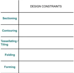
3.1 Sectioning ... 37 3.2 Contouring ... 40 3.3 Tessellating / Tiling ... 43 3.4 Folding ... 47 3.5 Forming ... 51 4 DESIGN CONSTRAINTS ... 55 4.1 Function ... 56 4.2 Material Properties ... 61
4.3 Assembly Technique of the Parts ... 63
4.4 Machine Properties ... 68
vii
CONTENTS
5 THE PROPOSED CLASSIFICATION MATRIX ... 81
6 CONCLUSION ... 87
REFERENCES ... 90
viii
LIST OF TABLES
Table 3.1 Literature Survey for Digital Fabrication Techniques in Architecture ... 34
Table 3.2 Recurrence Table ... 36
Table 3.3 Analysis of Recurrence Table ... 36
Table 3.4 Classification in the Related Literature and Scope of the Thesis ... 36
Table 3.5 Main Column of the Generated Matrix ... 36
Table 4.1 Examined Projects... 56
Table 4.2 Function – Digital Fabrication Technique Numerical Table ... 57
Table 4.3 Material Properties – Digital Fabrication Technique Numerical Table ... 62
Table 4.4 Assembly Technique of the Parts – Digital Fabrication Technique Numerical Table ... 64
Table 4.5 Machine Properties – Digital Fabrication Technique Numerical Table .... 69
Table 4.6 Parametric Design Patterns – Digital Fabrication Technique Numerical Table ... 71
ix
LIST OF FIGURES
Figure 2.1 ENIAC as an early modern computer ... 17
Figure 2.2 Yershov’s human-machine interaction diagram ... 18
Figure 2.3 Applying design constraints to SketchPad ... 18
Figure 2.4 Algorithmic System Diagram ... 23
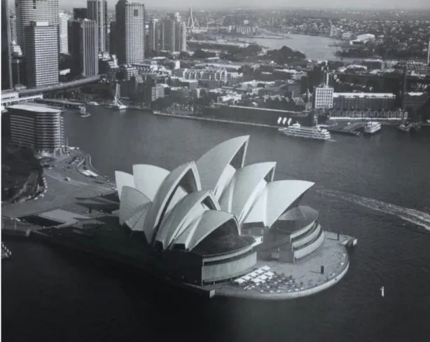
Figure 2.5 Sydney Opera House, Jørn utzon ... 26
Figure 2.6 Fish Sculpture, Frank Gehry ... 27
Figure 3.1 Roof of the Chapelle Notre Dame du Haut at Ronchamp, 1950 ... 38
Figure 3.2 Artists Space Installation, Rendering of Sectional Ribs ... 38
Figure 3.3 Dunescape Installation ... 39
Figure 3.4 Carvings on a rooftop of an Early Jain Temple ... 40
Figure 3.5 Design 306 ... 42
Figure 3.6 Continuous Surfaces of One Main ... 43
Figure 3.7 Shapes of Tessellations ... 44
Figure 3.8 M.C. Escher’s drawings ... 44
Figure 3.9 Buckminster Fuller’s geodesic dome... 45
Figure 3.10 Performance Criteria of Patterns - Study of a cube using computational fluid dynamics, “dirty geometry” ... 46
Figure 3.11 West Side Convergence Project... 47
Figure 3.12 Shell roof of a restaurant in Xochimilco, Mexico City ... 49
Figure 3.13 OMA’s Educatorium Project ... 50
Figure 3.14 CCTV Building open plan ... 51
Figure 3.15 Berliner Philharmonie ... 53
x
Figure 4.1 Function as structure and volume in Loewy Bookshop (7) ... 58
Figure 4.2 Sectioning technique generating structure, surface and volume of Mafoombey (9)... 58
Figure 4.3 Contouring technique generating structure and surface for Bonewall (11) and Softshelf (19) ... 59
Figure 4.4 Marble Curtain (24) and Yokohama International Port Terminal (36), tessellating and folding techniques generating structure with surface ... 60
Figure 4.5 Digital Origami (37), folding technique generating structure with surface ... 60
Figure 4.6 NGTV (50) generating volume and surface with forming technique ... 61
Figure 4.7 GRADIENT SCALE (14) subtractive process of contouring ... 62
Figure 4.8 Carved concrete sound barriers of A2 Ringroad Infrastructure (22) with tessellating technique ... 63
Figure 4.9 Mortise-tenon connection of Serpentine Gallery Pavilion (3) (2005) by Alvaro Siza and Eduardo Souto de Moura ... 65
Figure 4.10 Restaurant and Event Space (8) project, bolting materials from perforations ... 65
Figure 4.11 Door with Peephole (13) that is fabricated as a single module with contouring ... 66
Figure 4.12 Binding technique for Airspace Tokyo (29), California: Stage Set for John Jasperse (30) and Nubik (33) projects ... 67
Figure 4.13 Music Theatre in Graz (47)... 67
Figure 4.14 Structural elements for Berkeley Hotel Entrance Canopy (46) ... 68
Figure 4.15 Laser cut and Folded geometry of Vector Wall (32) ... 69
Figure 4.16 Superforming process of Shiatsu (48) ... 70
Figure 4.17 Controller Parametric Design Pattern in Bubble (44) ... 72
Figure 4.18 Repeated dot patterns of Aoba-tei Restaurant (35)... 73
Figure 4.19 Subdivisions of 27 (Technicolor Bloom Project) ... 74
xi
Figure 4.21 Tiled surfaces of Satin Sheet (43) ... 75 Figure 4.22 Recursion Parametric Design Pattern in West Coast Pavilion (26) ... 76 Figure 4.23 C Wall (38) demonstrating Packing Parametric Design Pattern ... 77 Figure 4.24 Interlocking cross joint system of (c) Space (4) as Weaving Parametric Design Pattern ... 78 Figure 4.25 Branching Parametric Design Pattern for Structural Purposes in Helios House (23) and Entry Paradise Pavilion (31) ... 78 Figure 4.26 Dynaform (1) with Force Field and Repetition Parametric Design Patterns ... 79 Figure 4.27 Dragonfly (39) with Repetition, Subdivision and Packing Patterns ... 80
12
CHAPTER 1
INTRODUCTION
Architectural process is mainly concerned with two primary activities - designing and making - which inform each other in a continuous dialogue as projects progress from concepts, through design development to final form. (Dunn, 2012) Growing digital technologies can contribute to the workflow between conception and production for architectural practices to gain fluidity (Dunn, 2012). According to Iwamoto, “Digital practices have the potential to narrow the gap between representation and building, affording a hypothetically seamless connection between designing and making” (2009: 4). Also, digital developments affect the practice of architecture. Recently, the role of the architect has shifted close to the making process as new as it is to designing (Wannan, 2016). Architects begin to both take part in the conceptual design stage and construction process by proposing ways of fabricating the design (Wannan, 2016).
Computational design is a recent field of research with its subcategories that span to a background of approximately 20 years (Gannon, 2013). Computer Aided Design, which consists of a range of programs that produce different results can be considered as a subcategory of computational design. Some CAD programs create two dimensional drawings while others have the capability of creating three dimensional renders and animations. With Computer Aided Manufacturing (CAM), three dimensional generated models with CAD programs are converted into numerically controlled machines. Thus, as the last step of a design process, digital fabrication has become a way of production for the last 15 years (Iwamoto, 2009). Digital fabrication process can create parts of the design by using computer controlled machines as tools and these machines translate the computer generated data to physical artifacts.
13
Digital fabrication has diverse potentials through the use of different technologies and techniques. These diversifications may lead to various contributions to the design processes.
Digital fabrication is considered as one of the final stages of design process. Fabrication technologies and techniques that designers prefer can explicitly and implicitly contribute to design ideas. While making a design, decisions of which machine and method to use should ideally correspond to the design intent and the machine capability (Iwamoto, 2009).
1.1 Problem Statement
This study investigates the features of digital fabrication techniques. It is expected that the choice of digital fabrication technique can affect even the conceptual design process and specifying the potentials and drawbacks of fabrication techniques will help to determine which technique best suites the designer’s intention.
Due to the fact that digital fabrication is a newly developing area, there are inconsistencies in between the terminology and the descriptions of digital fabrication techniques in the related literature.
Although digital fabrication is the last step of a design process, it is expected that choosing the fabrication technique during the initial phases of design will positively contribute to the design process.
1.2 Aim and Scope of the Thesis
This thesis aims to analyze digital fabrication techniques and classify them according to their features. The overlaps in the newly developing literature will be determined. This study will also provide a classification matrix for the implications and limitations of different techniques that has a potential to optimize the design. The matrix is
14
proposed for the aim of clarifying the relation between digital fabrication techniques and the design constraints.
This matrix is expected to serve the designers during the design process. The classification matrix, comprising the design constraints and their relation with the fabrication technique, is expected to lead the designer in the selection of the technique that suites her design intentions the best, in early design process.
The classification matrix also aims to contribute both to educational and practical sides of architecture.
1.3. Structure of the Thesis
This thesis comprises of six chapters. The chapters are organized respectively as follows:
The first chapter of the thesis introduces the problem statement, aim and scope, and structure of the thesis.
In the second chapter, a short history of computers in architecture is given to demonstrate the change in the architectural design process. As the technology develops and new tools begin to emerge, the design process changes with computational power. Brief information about computer aided design (CAD), computer aided manufacturing (CAM) and computational design with their subcategories is given. Moreover, digital fabrication, as an extension of the computational power is discussed.
The third chapter focuses on digital fabrication techniques in architecture. The confusion, shifts and overlaps in the terminology for digital fabrication techniques in architecture are simplified and classified according to the recurrence tables. With this simplification, digital fabrication techniques are classified as sectioning, contouring, tessellating – tiling, folding and forming. These techniques are discussed in detail.
15
The fourth chapter gives information about the design constraints are determined by analyzing 10 project examples for each digital fabrication technique. These design constraints are respectively function, material, assembly technique of the parts, fabrication machine and parametric design patterns.
In the fifth chapter, by integrating the digital fabrication techniques and the design constraints in a table, the proposed matrix is generated. The classification matrix is explained in detail to clarify the usage for the designers.
The sixth and the last chapter of the thesis is the conclusion. In this chapter, discussions of the classification matrix and suggestions for further studies are proposed. The sixth chapter is followed by a list of references and the appendix.
16
CHAPTER 2
HISTORY OF COMPUTERS IN ARCHITECTURE
Designing and fabricating practices in architecture have been improving and evolving since 1990s. Computers are widely involved in architectural design processes. Not only as visualization and representation tools, but they also serve for computational design and digital fabrication purposes. Today, digital technologies in architecture enable the design process to be performed as a whole from concept generation to the fabrication phase. In other words, these technologies change the focus of architecture from being on the result, to generating the design process and production.
In order to comprehend computers’ interaction with architecture, it is necessary to go back in history and have a look at how computers began to be used in architectural design. Although analog computers have existed for centuries, digital computing has become part of our lives since World War II era with code breaking machines (Reichardt, 1978). Early modern computers were used as automation tools by scientists and mathematicians. For example, ENIAC, calculating mathematical tasks for pattern recognition and physical simulations can be regarded as one of the early modern computers (Rosen, 1969). ENIAC was mainly used to make these calculations with more reliable, precise and fast manner (Figure 2.1).
In the 1960s, with the development of the first graphic systems, computers started to be used in architecture. Firstly, Yershov’s automation typology as a director-agent
model of interaction was invented in 1963 as a one-way “closed chain of transfer and processing of information” (Yershov, 1965: 315). This invention comprises of a closed black box and a portal for incoming and outgoing information (Figure 2.2).
17 Figure 2.1: ENIAC as an early modern computer
(http://www.computerhistory.org/revolution/artifact/78/321)
Our interaction with Computer Aided Design (CAD) programs today is similar with the director-agent model of Yershov’s as the command-line, mouse and the script editor are input devices of computer for desired outcomes (Gannon, 2013). The ‘desired outcomes’ should be precisely stated, otherwise the communication model breaks down. In other words as Gannon implies, “the scope of the machine’s usefulness is limited by the mind of the human” (2013: 18).
18
Figure 2.2: Yershov’s human-machine interaction diagram (Gannon, 2013: 18)
Unlike the Yershov's human-machine interaction, SketchPad, invented by Ivan Sutherland in MIT in the same year, enabled people and computers to communicate through line drawings (Sutherland, 1963). Sutherland has created an interactive and visual interface with Sketchpad, which aims to serve for computing function to artists, architects and designers. Sketchpad also separated “programming a computer” from “using a computer” (Gannon, 2013: 18). There are two components of the invention. A light pen and a dock of push buttons that provide designer to sketch 2D and 3D graphics directly on the computer screen (Figure 2.3). Hence, the designer may begin with a vague idea for the final graphic object in collaboration with the computer. This collaboration has the potential to reveal unforeseeable results from abstract ideas of the user. In the meantime, cybernetic theory was disseminated. The theory promotes a new way of man-machine relationship, which uses computers to widen the human intellect by being a representation tool in the design process.
Figure 2.3: Applying design constraints to SketchPad – Before (left) and after (right) (Gannon, 2013: 19)
19
As such, architecture can be formulated according to the complex interrelations between material parts and social engagement; shaping form, space and structure while understanding and developing them (Pask, 1969). According to Menges & Ahlquist (2011) the Sketchpad can be considered as an improvement for the cybernetic view of the man-machine relationship, and synthesis of process as a mirror to the working of the resulting system.
On the other hand, as Chrisman (2006) implies, with Sketchpad, an interface was presented as a methodology for maintaining rule-based geometric associations. Ivan Sutherland explains his invention with these words (Sutherland, 1963: 21-23):
“Construction of a drawing with Sketchpad is itself a model of the design process. The locations of the points and lines of the drawing model the variables of a design, and the geometric constraints applied to the points and lines of the drawing model the design constraints which limit the values of design variables.”
Besides Sutherland’s Sketchpad, mechanization of the design process continued to be explored through software such as the first drafting software URBAN 5 by Negroponte and Groisser (1970) and space planning software as COPLANNER by Souder and Clark (1964) (Mitchell, 1977). In the 1980s, with CATIA and AutoCAD, architecture firms began to use CAD programs in offices.
2.1. Computer Aided Design and Computer Aided Manufacturing
Before the introduction of CAD, architects were drawing designs on a paper and constructors were building the design as exactly as they could. In 1960s, with the development of computer aided design programs, design processes began to change
20
and CAD technologies began to be used as technical support for planning and construction phases of the design (Wiertelarz, 2016).
CAD comprises of numerous programs with their various results. Some of them are capable of creating only two dimensional drawings while others can produce three dimensional renders and animations. They can be categorized as 2D, 2 ½ D, and 3D CAD programs. With them, designers are able to use repetitive tasks like ‘copy’, ‘cut’ and ‘paste’ which provide a quicker working environment. These commands repositions or removes the elements of the design rapidly. Another advantage of using CAD programs is documents’ transferability between some software platforms and formats (Dunn, 2012).
Revealing a computational model as a physical object is possible for computational design with CAD – CAM (computer-aided design/computer aided manufacturing) techniques. These tools benefit output information from the designers computer to drive computer numerically controlled (CNC) machines. Also, digital fabrication technologies and techniques enable computationally designed forms to be realized directly (Jacobs, 2013).
2.2. Computational Design
“The power of computation, which involves vast quantities of calculations, combinatorial analysis, randomness, or recursion, to name a few, point out to (sic) new ‘thought’ processes that may have not ever occurred to the human mind. These ‘idea generators’ which only to expand the limits of human imagination but also to point out the potential limitations of the human mind (Terzidis, 2006: 18).”
21
Computational design is a term that is confused with computer aided design in contemporary architectural discourse although they have totally different meanings (Fathi et al., 2016). As computer aided design (CAD) is mentioned above, it means ‘computerization’ in architectural practices while computation process involves methods that produce new information from input data rather than merely storing and organizing it (Menges & Ahlquist, 2011). Basically, both of them are procedures that one (computation) broadens the amount and specificity of information and the other (computerization) gets only given, specified information in the beginning (Terzidis, 2003). This differentiation comes from the approach through the design, not from skills or set of knowledge of the designer. In computer – aided approach, the process starts with specific information and is concluded with an object whereas computational process begins with elemental properties and generative rules to end with information which derives form as a dynamic system (Menges & Ahlquist, 2011). As Vitta states (1990), in computational design, computers not only contribute to the development and presentation of the design but also to the “running” of the design.
To reveal a computational model, it is not only important to master computational tools but also to adopt computational thinking. Computational thinking is a problem solving process in which mathematical and logical instructions take part. In computational design, mathematical thinking with calculation skills of computers; “based on well-defined steps which necessitates a design strategy to be developed at the initial phase of design process is needed” (Çinici, Akipek, Yazar, 2008: 19).
According to Scheer (2014), computational design may be classified in terms of three categories; computational design which the designer creates shapes manually, parametric design and algorithmic design.
22
2.2.1. Computational design which the designer creates shapes manually
Thanks to the graphical interface provided by the computer programs used, the designer can control the complex mathematical processes and obtain forms with this category (Scheer, 2014). In forms created with this way, the designer already has a pre-conceived form and the computational power is used to explain, analyze and fabricate this form. In this method, each step is not carried out with the computer program. Thus, this method is suitable for “willful shape making” (Scheer, 2014). The
disadvantages of the method are the inability of the generated model to be edited and the model being a single object, elements of which cannot be reached separately.
2.2.2. Parametric Design
“Rather than the designer creating the design solution (by direct manipulation) as in conventional design tools, the idea (of parametric design) is that the designer establishes relationships by which parts connect, builds up a design using these relationships by observing and selecting from the results produced (Woodbury, 2010: 24).”
Parameter is a value that is assumed as stable for defined scenarios, but may change in different situations. Although it is sometimes defined as a limit or constraint, it actually represents a value (Dunn, 2012). In parametric design, some values that regulate and control the design process are assigned to elements or group of elements in design and relationships and connections between these values are determined. The final form is composed of parameters – “a set of values” - and algorithms – “computational procedures” - that run these parameters (Scheer, 2014: 141).
The traditional design process and the parametric design process are clearly separated from each other (Scheer, 2014). In traditional design process, the designer starts the
23
process by envisioning a form, while in parametrical design process, the form is the result of abstract relationships. As Sheer states, in terms of form formation, the traditional design process is defined as "top-down", while the parametric design process is "bottom-up" (Scheer, 2014: 141).
Parametric design has two main contributions to the design process. First of all, after all the parameters are determined, the system can work on its own and novel solutions that even the designers cannot foresee can be generated. Secondly, when all parameters are set, the designer can evaluate many options in a short time frame.
2.2.3. Algorithmic Design
Algorithms are defined as “a computational procedure for addressing a problem in a finite number of steps” by Terzidis (Terzidis, 2011: 94). In algorithmic design, the algorithmic system may be implemented repeatedly by ‘recursion’. In this process, the output of each recursion is used as the input of the following one (Figure 2.4).
24
In the algorithmic design, starting as a parametric design process, the designer designs the algorithmic system, not the final shape. The designer writes an algorithm that defines the design requirements, named as ‘selection criteria’, and features such as material properties (Scheer, 2014). The shapes resulting from each implementation are tested to see if they can meet the ‘selection criteria’ (ibid). Remaining shapes are then used as inputs for the next run. This process is repeated many times.
2.3 Digital Fabrication in Architecture
Architecture of an era may be described with the capacity of representation and fabrication techniques employed by architects and constructors. Thanks to the CAD, CAM and computational design tools, both the design and construction have become largely digital. As William Mitchell indicates (2001: 354) “architects draw what they can build and build what they can draw”. To work with Euclidean geometries, for example, traditional drafting instruments like straightedge and the compass were used to draw straight lines and circles in material. Traditional drafting tools for Euclidean geometry were developed partly by architects for individual use and also different technologies that were developed in other fields have been introduced into architecture and construction (Kolarevic, 2003). Although architecture is a rather receptive field to technological developments, the assimilation of technological tools in the field took time (Krauel, 2010).
In line with this, computers began to be integrated in architectural design process gradually. In the beginning, they were involved in architectural design as ‘drawing tools’ and had no impact on the form and construction of the building (Dunn, 2012). They were only a representation tool and offered speed and optimization for the drawing process. Then the styles took over the use of computers; deconstructionism, for instance, made architects explore digital technologies out of “sheer practical
25
necessity” (Krauel, 2010: 11). For realizing continuous, curvilinear surfaces, fabricating the spatial and tectonic characteristics of complex forms became a necessity. Digital tools satisfied this need by making “constructability a direct function of computability” (Kolarevic, 2003: 33). Kolarevic named this change in architectural design as “file to factory” process (Kolarevic, 2003: 31). Lisa Iwamoto expresses this continuum with these words (Iwamoto, 2009: 5):
“For many years, as the process of making drawings steadily shifted from being analog to digital, the design of buildings did not really reflect the change. CAD replaced drawings with a parallel rule and lead pointer, but buildings looked pretty much the same. This is perhaps not so surprising—one form of two dimensional representation simply replaced another. It took three-dimensional computer modeling and digital fabrication to energize design thinking and expand the boundaries of architectural form and construction.”
With computability there is no need to think whether a particular form is buildable. Fabrication becomes a direct consequence of digitally defined projects. It is the “logical extension to digital design”, depending on computers’ precision and potential to survive the complexity (Marcos, 2011: 1037). As William Mitchell observes, a fabrication machine can be considered as a device that “automatically translates a digital object in the design world into a material reality” (Mitchell, 2004: 78).
One of the pioneer projects where digital technologies were used for construction is Jørn Utzon’s Sydney Opera House which was completed in 1973 (Kerr, 2003) (Figure 2.5). The intended seashell structure could not be calculated and built with traditional techniques; thus that paved the way for the use of digital technologies in the construction process (Krauel, 2010). Later on, Frank Gehry’s Fish Sculpture in
26
Barcelona, Spain (1992) is another project that is fabricated digitally (Figure 2.6). The financial and programmatic constraints of the art work caused the design team to search for a computer software that can provide optimization for design and fabrication process (Kolarevic, 2003). They came up with CATIA, which was already developed by ship and airplane engineers to work with three dimensional digital models and CNC machines for prototyping (Krauel, 2010). The program generated a digital workflow using almost no traditional drawings.
27
Design information has never been linked so directly to the physical production of architecture (Bonwetsch, et. al., 2006). Today, it is possible to design and construct a building in a total digital process that allows for complex forms.
There are three main steps for designing and constructing a building following a continuous digital workflow (Krauel, 2010). The first step is designing the building as a three dimensional digital model instead of drawing plans and elevations. This 3D model differentiates from renderings that are used for visualization of architectural projects (Dunn, 2012). Renderings usually comprise of surface models whereas 3D model for digital workflow is generally formed with NURBS surfaces and solid modeling (Dunn, 2012).
Figure 2.6: Fish Sculpture, Frank Gehry (https://casitasitges.com/its-a-bird-its-a-plane-no-its-a-fish-a-frank-gehry-sculpture/)
28
The geometry of the design should be clearly and unambiguously defined for a seamless design process. After modeling, the second step is defining the dimensions and properties of elements parametrically for testing and optimizing the geometry (Krauel, 2010: 12):
“A family of parametric variations all stem from the same characteristic shape but slightly vary in dimension or shape from one to another. They are instances of the same design. The essential shape and constituent elements of the design are clearly set within certain specified constraints, but the exact dimensions and shapes of individual elements vary from shape to shape.”
There are hierarchy of dependencies between the relations of parameters. Finally, as the third and last step, information of a three dimensional model that originates from NURBS surfaces and solid modeling can be directly converted to CNC machines. Digital fabrication also allows for making copies of the same object or diversifying it. Before digital fabrication machines, mass production which refers to industrial manufacturing was preferred (Dunn, 2012). For economical properness, building components in the 20th century were geometrically simple and limited in terms of type (Dunn, 2012). With digital fabrication technologies and techniques this situation has changed. Today, economics and efficiencies of production are not related with the complexity or vastness of the designed elements. The term ‘mass production’ gave way to ‘mass customization’, which enables unique, highly variable components. With mass customization, “it is just easy and cost effective for a CNC machine to produce 1000 unique objects as to produce 1000 identical ones” (Kolarevic, 2001: 275).
From a computational perspective, Mitchell claims that (as cited in Wiertelarz, 2016: 78) we can describe the process of a design development as “translating a digital model
29
from some design world into a sequence of instructions for some particular fabrication machine”.
In this process architects are becoming much more directly involved in the fabrication of the design by creating design information that drives the fabrication equipment (Iwamoto, 2009). As Castle argues (2005: 4) “the onset of CAD/CAM interfaces that allows designers to design directly for manufacture has placed production potentially back in the hands of architects”.
30
CHAPTER 3
DIGITAL FABRICATION TECHNIQUES IN
ARCHITECTURE
Digital fabrication reveals realistic choices for representation, evolution and redesign of complicated forms (Valamanesh & Shin, 2012). According to Sass and Oxman (2006), the use of digital process in architectural design improves creativity and it supports the continuity in between different stages of design. Although digital fabrication may seem to be a later stage of the design process, that does not mean it should be thought about in the end. Conversely, fabrication techniques require the designer to evaluate the elements for manufacturing much earlier in the ideation stage (Dunn, 2012). Knowing which technique will be used for fabrication affects the design process (Baquero & Giannopoulou, 2015). In that sense, the constraints and the technique that suits the design intention best should be thought upon in the early stages of design. Believing that the choice of the fabrication technique has the potential to affect the design process, the aim of this thesis is to propose a classification matrix demonstrating the relationship between the digital fabrication techniques and the design constraints.
As digital fabrication is a newly developing area, there is an ongoing confusion, shift and overlap in the terminology among fabrication techniques. Same techniques are often referred to with different names, and some of the techniques are not even referred to in all of the resources.
Same techniques that are referred to with different names are painted with the same color for simplification purposes.
31
According to the literature survey it is observed that; tessellating, tiling, and triangulation are defined with different headings, while they are similar in operation. Tiling is mentioned in Nick Dunn’s book with these words:
“The process of tiling, also referred to as ‘tessellating’, involves the development of figures or shapes that when assembled together form a coherent plane without gaps or overlaps. Such tiles may have any geometric shape provided they fit together, even if the tiles change in size and shape across the plane itself” (Dunn, 2012: 166).
Also Lisa Iwamoto explains “tessellation, or tiling” as “a collection of pieces that fit together without gaps to form a plane or surface” and adds that tessellations “can be virtually any shape so long as they puzzle together in tight formation” (Iwamoto, 2009: 36). Tessellating and tiling are already used in these two references interchangeably. However, Branko Kolarevic uses polygonal tessellation and triangulation interchangeably (Kolarevic, 2018: 120). In ‘Manufacturing of Innovative Self-Supporting Sheet-Metal Structures Representing Freeform Surfaces’ (Bailly et al., 2014: 52), it is stated that “triangles have been used, that vary in shape and size” for the study and they can be adapted “to any arbitrary surface geometry” to fabricate the intended form with “tessellation” technique. According to these definitions, triangulation refers to using triangles for tessellation patterns and becomes a specific case for this thesis. Thus, triangles can be considered as one of the patterns for tessellating/tiling technique.
Likewise; sectioning, bilateral contouring, intersecting profiles and waffle structuring actually refer to the same technique under different headings (Table 3.3). According to Dunn, “Sectioning is a method of profiling components in relation to a surface
32
geometry. By taking a series of sectional cuts through a digital model, it offers a quick and effective way of gathering the necessary data to inform a CAD/CAM process.” (Dunn, 2012: 158). Similarly, Iwamato states that “Rather than construct the surface itself, sectioning uses a series of profiles, the edges of which follow lines of surface geometry. The modeling software’s sectioning or contouring commands can instantaneously cut parallel sections through objects at designated intervals.”(Iwamoto, 2009: 10). Moreover, Kınayoğlu implies that sectioning “involves the creation of cross-sections of the aimed surface in singular or varying directions” (Kınayoğlu, 2017: 76). If the sections are not assembled laterally, it is called “bilateral contouring” (Sass, 2007). Likewise, if the sections are cutting each other with varying angles, the technique is defined as “intersecting profiles” (Baquero & Giannopouolu, 2015) or “waffle structuring” (Wannan, 2016).
Therefore, to propose the matrix, two consecutive steps are taken. First, a simplification and classification in the terminology is carried out. For simplifying the terminology, the techniques are classified after a literature survey. 18 references are examined in this survey (Table 3.1).
Then secondly, a recurrence table is created based on these classifications (Table 3.2). Recurrence table demonstrates the mostly preferred headings in the references. For instance, sectioning and waffle structuring headings define the same way of fabricating. According to the recurrence table, sectioning will be the title of the technique as it is used 8 times versus waffle structuring, which is used twice in the references. On the other hand, future fabrication of architecture, use of ruled developable surfaces and unfolding are only referred to in the references once and they cannot be related with any of the classifications. Thus, these 3 techniques will not be mentioned in the thesis.
33
After the recurrence table analysis, 9 different techniques remained; comprising of sectioning, contouring, tessellating / tiling, folding, forming, two dimensional fabrication, subtractive fabrication, additive fabrication and formative fabrication. In literature, these techniques are grouped mainly in two categories. The first category is related with architectural design constraints and the second category is related with digital fabrication machines and the technology used (Table 3.4).
As shown in the table, two dimensional fabrication, subtractive, additive and formative fabrication are defined and classified according to the specific fabrication machine and the technology used. For instance, in two dimensional fabrication, “various cutting technologies, such as plasma-arc, laser-beam, or water-jet, involve two-axis motion of the sheet material relative to the cutting head and are implemented as a moving cutting head, a moving bed, or a combination of the two.”(Kolarevic, 2018: 120). Similarly, additive fabrication mainly depends on the fabrication machine used such that “incremental forming by adding material layer by layer with technologies such as Selective Laser Sintering (SLS), 3D Printing (3DP), Laminated Object Manufacture (LOM) or Fused Deposition Modelling (FDM)” (Wiertelarz, 2016: 84). Also, subtractive fabrication is dependent on the technology used as it is the “removal of a specific volume of material from solids using electro-, chemically or mechanically reductive multi axis milling process” (Wiertelarz, 2016: 82). Lastly, with formative fabrication “mechanical forces, restricting forms, heat, or steam are applied on a material so as to form it into the desired shape through reshaping or deformation, which can be axially or surface constrained” (Kolarevic, 2018: 121).
34
35
On the other hand, as it can be mentioned from the definitions of sectioning and tessellating/tiling above; the remaining five techniques (sectioning, contouring, tessellating/tiling, folding and forming) are defined according to the design constraints like function, geometry, scale etc. The constraints originate from the designer rather than technological possibilities (Dunn, 2012). For instance, according to Iwamoto (Iwamoto, 2009: 90), “Contouring is a technique that reshapes this surface and creates a three dimensional relief by removing successive layers of material.” The technique “removes unnecessary material starting from the top level and going down, reaching to the desired three-dimensional object at the end.” (Kınayoğlu, 2017: 73). Also, Lisa Iwamoto defines folding as a technique that “turns a flat surface into a three dimensional module creating not only form but also structure with the geometry” (Iwamoto, 2009: 62). Moreover Kınayoğlu implies the same technique with these words: “The folding technique uses an operation to attain the desired shape instead of creating a new form” (Kınayoğlu, 2017: 79). A language is generated using the characteristic of fold that also creates a source of architectural and structural motion (Moussavi, 2009) and “the combination of several folds creates a folding” (Meyer et al., 2015: 443). it. Lastly, in forming, “the possibilities of moulding” (Marcos, 2011: 1045) is explored to generate components. Mainly for mass production “architectural elements such as façade panels, detail components and other hardware” (Dunn, 2012: 148) can be fabricated with the technique.
This thesis focuses on the digital fabrication techniques that are defined according to the architectural design constraints (Table 3.4). The selected five techniques establish the main column of the proposed matrix (Table 3.5). These techniques are sectioning, contouring, tessellating / tiling, folding and forming.
36 Table 3.2: Recurrence Table
Table 3.3: Analysis of Recurrence Table
Table 3.4: Classification in the Related Literature and Scope of the Thesis
Table 3.5: Main Column of the Generated Matrix
37 3.1 Sectioning
In the sectioning technique, series of profiles are used to construct the surface geometry and these profiles can be connected to each other with various methods such as interlocking, mounting and laminating. For the necessary data to inform CAD/CAM process of sectioning, sectional cuts are taken at intervals from a computer model. Besides fabricating curvilinear forms, the designer can understand and communicate the relationships of form, surface and space by slicing the design through digital modeling software (Dunn, 2012). The commands on the modelling software such as sectioning and contouring enables the designer to generate parallel sections (Iwamoto, 2009). In sectioning, it is possible to create surfaces; with supports and/or as skins (Bollinger, Grohman & Tessman, 2010). Also it is possible to generate a whole volume by laminating the sections one after another.
Although sectioning is often mentioned as a –new- digital technique, it actually has a long history traditionally in construction industry (Iwamoto, 2009). The technique was first used in ship industry in the Middle Ages and today, it is still effective in the aircraft industry to make doubly curving surfaces (Eyres & Bruce, 2012). In airplane bodies and also boat hulls, sectioning is used to create ribs for the structure (Iwamoto, 2009). The surface material can either be described in section as “curves along the surface” or “unrolled into flat pieces” (Iwamoto, 2009: 10).
Sectioning was used as a building technique in the pre-digital era (Iwamoto, 2009). Le Corbusier for instance, designed the roof of the chapel of Ronchamp constituting a series of structural concrete ribs, laterally joining each other with crossbeams (ibid). The reason why Le Corbusier used this technique is based on the fact that the structure becomes lightweight with “accurate edge profiles for a non – uniform shape to align and support surface material” (Iwamoto, 2009: 10) (Figure 3.1).
38
Figure 3.1: Roof of the Chapelle Notre Dame du Haut at Ronchamp, 1950 (Iwamoto, 2009: 11) Another architect who used digitally generated sectional construction for his designs is Greg Lynn. He used computational power in his projects both for early design and fabrication phases (Iwamoto, 2009). Four of his projects from the book Animate Form were presented in New York, in 1995, for Artists Space Exhibition (Lynn, 1999) (Figure 3.2). Curvilinear form of the projects are designed and fabricated with parallel sectioned ribs using plastic sheet material.
Figure 3.2: Artists Space Installation, Rendering of Sectional Ribs (Iwamoto, 2009: 11)
A more contemporary example is SHoP Architect’s Dunescape installation that won
MoMA/P.S.1’s Young Architects Program in 2000
(http://www.shoparc.com/projects/dunescape-at-moma-ps1/). It is an “architecturalized landscape” that is fabricated with stacked, dimensional lumber
39
(Iwamoto, 2009: 12) (Figure 3.3). Digitally driven methodology of the project enabled the designers to use the section drawings for realizing the project (Iwamoto, 2009). SHoP architects also used the same technique for making a scaled model of the design.
As seen in the example of Dunescape, sectioning technique can be used for fabricating the whole 1:1 scale design and its scaled model. For creating multi scaled designs, sections are produced with two dimensional planar materials. These materials can be cut with computerized cutting tools like laser, water-jet, plasma cutters and CNC routers (Iwamoto, 2009).
Figure 3.3: Dunescape Installation (http://www.shoparc.com/projects/dunescape-at-moma-ps1/) Each fabrication technique has different potentials that differentiates it from the others. Sectioning assembly has the capacity of augmenting structural and tectonic properties of the surface (Bechthold, 2008). Moreover, series of profiles can be connected to each other easily and economically.
40 3.2 Contouring
With contouring technique, a three dimensional form is created as a whole by removing material from a solid object. The surface is reshaped with a subtractive process. Unlike sectioning technique, in which planar materials can be merged with each other with various methods, contouring generates the whole form by carving a monobloc object. End results are generally identical in physical appearance with sectioning technique, although their creation processes and the way material is used are different.
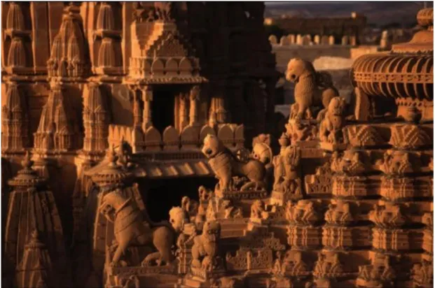
Figure 3.4: Carvings on a rooftop of an Early Jain Temple
(https://www.wmf.org/sites/default/files/article/pdfs/pg_22-25_jaisalmer.pdf)
In sectioning, separate pieces are joined together to create a design, although by contouring, a volume is removed from a monobloc object like carving (Kolarevic, 2003). Carving enables designers to generate surface textures as in Greek columns (Marcos, 2011). In the history of architecture, many components like ‘ordered Greek-column capitals, friezes, rock-cut architecture and Jain temples’ are made with carving
41
different materials such as wood and stone (Iwamoto, 2009). For instance, around 12th
century Jain Temples in Golden fort Jaisalmer, which is a city in India, are made with carving different materials such as wood and stone, especially yellow sandstone (Figure 3.4) (Vaijyanti, 2013).
Carving was widely used in traditional construction practice until industrial standardization and manufacturing began to have effects on architectural production (Dunn, 2012). Due to industrialization, carving practice decreased in architectural field (ibid). However, with the emergence of digital fabrication technologies, contouring started to be used in creating surface textures similar to those in carving. Besides generating surface texture, ornamentation can also be produced. Main difference between traditional carving and contouring techniques is the set of tools used in each (Dunn, 2012).
Unlike traditional carving tools, such as riffler and knife, CNC routers and CNC mills are used as tools to reshape the surface in contouring (Marcos, 2011). With flat materials such as plywood, foams, stone slabs, particleboards and soft metals like aluminum and bronze, surface effects can be generated with contouring technique (Marcos, 2011). There are different variables in each design, varying according to the material characteristics and machine limitations. After they are identified, software creates a tool-path data with a programming language for CNC machines in the fabrication process (Iwamoto, 2009). This language is called G-Code and consists of operations with a series of commands like spindle position, speed and depth, for each individual job (Iwamoto, 2009). Also, whether the design will be produced as part-wise or as a whole is specified according to machine limitations (Kınayoğlu, 2017).
42
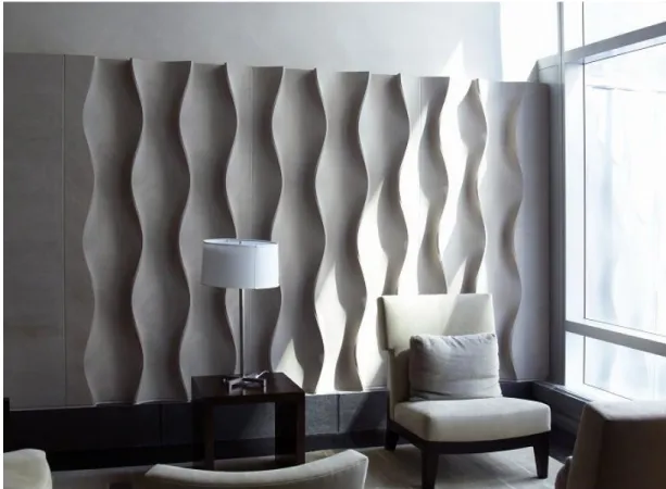
In spite of the contributions of the technique, the process is quite time intensive and the subtractive process generally causes extreme material waste (Iwamoto, 2009). The technique is used mainly for fabricating architectural components like panels, doors or facades of the buildings (Iwamoto, 2009). For instance, Design 306 by Philip Koether is a panel design, which is designed for a high rise residential building, Centria in New York (Figure 3.5).
Although machine limitations give the opportunity to use any stone material for the design, the panel was fabricated from Indiana limestone and milled with 3 axis CNC mill (ibid). The size of the panel can be changed according to the width of the space, while pattern ratio remains stable. Also, the selected pattern enables perforations for light settlements (Iwamoto, 2009).
Figure 3.5: Design 306 (https://www.architonic.com/en/product/erwin-hauer-studios-design-306/1028085)
43
Another project with contouring technique is One Main in Cambridge, Massachusetts, which was mainly designed for the penthouse offices of an investment group in green building and clean energy technologies (https://www.archdaily.com/778976/one-main-office-renovation-decoi-architects) (Figure 3.6). In the project, the floor and the ceiling are continuation of each other showing up a customized fabrication with a seamless fabrication logic (Dunn, 2012).
Figure 3.6: Continuous Surfaces of One Main (Dunn, 2012: 136)
Besides creating continuous surfaces, contouring technique provided crafted interiors with various functions instead of typical industrial components. Also, the technique enabled the whole project to be fabricated environmentally friendly (Dunn, 2012). Timber, as a sustainable, carbon-absorbing raw material, was milled with low energy digital tooling (ibid).
3.3 Tessellating / Tiling
In the analysis of the literature review, it was found out that in literature tessellating and tiling are used for referring to the same technique. In the technique, various figures and shapes generate the surface of the form with a tight formation, “constituting almost
44
a puzzle without gaps” (Iwamoto, 2009: 36). Tessellations can consist of regular shapes as triangle, square, etc. or it can also comprise of random shapes or figures (Figure 3.7).
Figure 3.7: Shapes of Tessellations
(https://www.mat.ucsb.edu/g.legrady/academic/courses/08w256/javier_p1/index.html)
Figure 3.8: M.C. Escher’s drawings (eagle, clowns, two birds, 1938) (https://www.mcescher.com/gallery/symmetry/)
These shapes create an area on the surface of the form, in which every point in the shape is located on the same polygon (Paoletti, 2017). Basically, tessellating is a technique, with which the designers can build smooth, curvilinear forms consisting of shapes on their surfaces using sheet materials. As in the previous technique, tessellating has also been widely used in the history of art and architecture (Dunn, 2012). For instance, M.C. Escher, a graphic artist in 1900s, was known for his tessellation art (Schattschneider, 2010) (Figure 3.8).
45
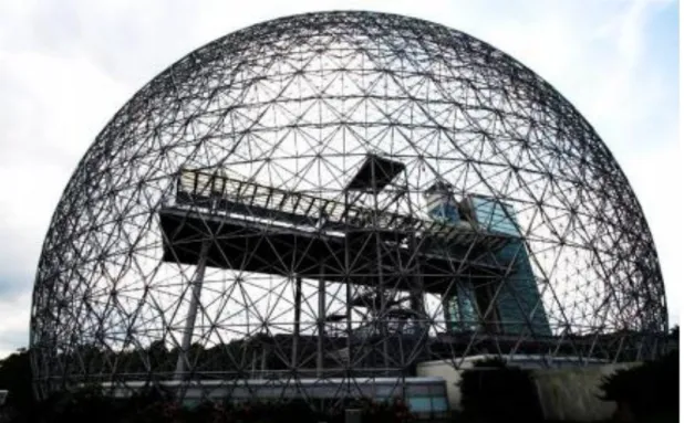
Besides art, tessellating as a term also represents “tiled patterns on buildings” and “digitally defined mesh patterns” (Iwamoto, 2009, 36). Due to the potentials of tile orientations and tessellations in providing structural integrity of the form, tiling has been used in architecture since the ancient times (Frampton, 1995). Roman mosaics; ceramics, marbles, and glass tiling in Islamic architecture; flower windows and floor tiles in Chinese architecture; or rose windows and arch arrangements in Gothic Cathedrals are typical tessellation examples (Chang, 2018). Buckminster Fuller’s geodesic dome is one of the first examples of tessellated surfaces (Iwamoto, 2009) (Figure 3.9).
Figure 3.9: Buckminster Fuller’s geodesic dome
(http://www.spatialagency.net/2009/08/24/buckminsterfuller_1-960x607.jpg)
In his book ‘Synergetics, Explorations in the Geometry of Thinking’, Fuller discusses building a new environment with less energy (Fuller, 1983). As the geodesic dome uses less raw material, he prefers to work with this special structure (Barbieri, D. et.al. 2016). The geodesic dome, which consists of triangular meshes, depends on a tensegrity structure, name derived by the combination of ‘tensional’ and ‘integrity’
46
(Barbieri et al., 2016). Structurally, the dome becomes stronger as it gets larger and also, every strut, opening and joint detail is identical with each other (Iwamoto, 2009).
Geometric tessellation concept first began to be used for digital design in architecture with computer graphics (Chang, 2018). The application of geometric tessellation in the digital era is generated by algorithms of the surface and these algorithms provide the designers to approximate surfaces (Iwamoto, 2009). Approximating surfaces is one of the significant advantages of tessellation as a digital design and fabrication technique, which means to be capable of placing various unique panels on the surface of the form for multiple scales and curvatures (Iwamoto, 2009). For algorithms, input of the surface results in the output of the geometry (Chang, 2018).
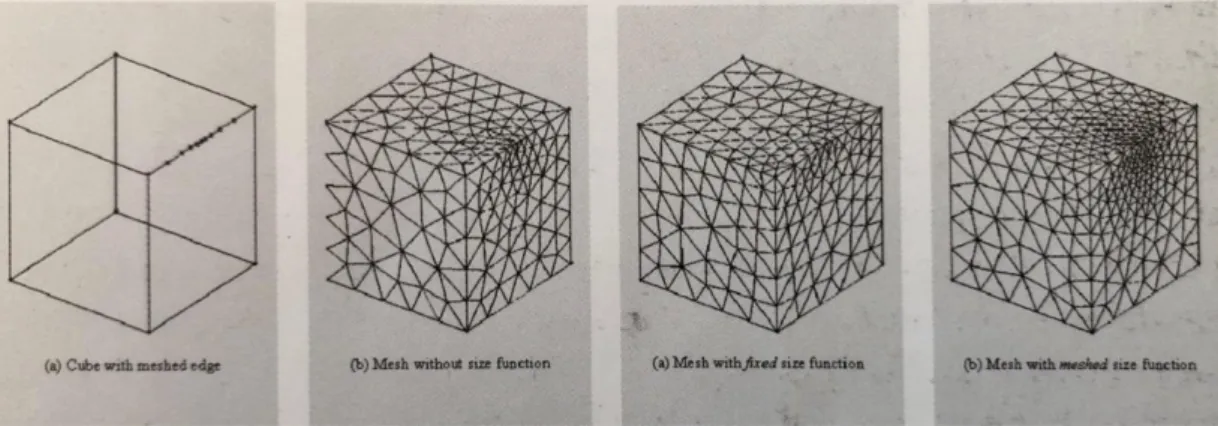
The resulting unique tessellations are not the result of the form that is intended to be built. Rather, the real potential of tiling lies in the performance criteria that is calculated via digital design programs (Iwamoto, 2009) (Figure 3.10).
Figure 3.10: Performance Criteria of Patterns - Study of a cube using computational fluid dynamics, “dirty geometry” (Iwamoto, 2009: 37)
Algorithms may enable constructional, structural, material, spatial, perceptual and programmatic constraints to be determined as a whole for optimized pattern solutions. Also, material investment can be provided via optimizing patterns with algorithms.
47
For example, in Reiser + Umemoto’s West Side Convergence project in New York (1999), algorithms are used to form triangulated tiling spaceframe of the design (Dunn, 2012) (Figure 3.11).
Figure 3.11: West Side Convergence Project (Gregory, 2003: 52)
Through algorithm components, both physical support - span and concept of being a whole continuous surface is achieved (Dunn, 2012).
3.4 Folding
In folding technique, a flat two dimensional material is pleated through two or more creases for generating three dimensional form without losing the characteristic of the material. According to Deleuze (2003: 26), folding is “a continuous variation of matter as a continuous development of form”. Basically, the technique has its roots from origami which “has evolved from traditional Japanese folk artto a design strategy for contemporary architecture and products” as Hemmerling indicates (2010: 89). Origami can be identified as “the art of folding paper” and guides the designers to generate complex geometries that have structural stability (D’Acunto & Gonzalez,
2015: 1). Since 1990s, folding strategies in architecture has been evolving for complex geometries (Hemmerling, 2010). Creased forms, folded plate structures and roof structures that are generated from hyperbolic curvature or accordion shape were the geometries for experimental studies in those times (Iwamoto, 2009). Ramm and Wall states that (as cited in Tomas & Pascual, 2010: 67), these studies were mentioned as
48
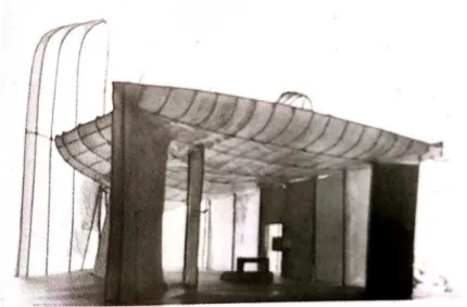
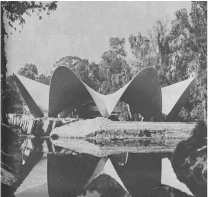
“prima donna of structures” by some authors due to their aesthetic values. Besides visual elegance, making formwork for casting concrete was easy and also the material has the potential to provide the design’s structural rigidity (Iwamoto, 2009). Also, in this new generation of architecture, structural performance and wide enclosures are provided with an economical manner (Iwamoto, 2009). As an example, Felix Candela’s restaurant project Los Manantiales was completed in 1958 as a shell roof of a restaurant in Xochimilco, Mexico City (Burger & Billington, 2006) (Figure 3.12).
It is an eight-sided groined vault that consists of four intersecting hyperbolic paraboloid saddles (Burger & Billington, 2006). Billington describes the structure with these words (as cited in Tomas & Pascual, 2010: 68):
“This roof is made up of eight hyperbolic paraboloidal vaults arranged on a circular ground plan of about 140 feet in diameter. Apart from deeply recessed glass wall, the paper-thin (15/8 inches) roof is the entire structure. Structure and form are one, and the thinness is expressed so powerfully that it is hard to believe the building is concrete. It is emphatically not a natural form; rather, it is artificial and the product of a disciplined mind.”
49
Figure 3.12: Shell roof of a restaurant in Xochimilco, Mexico City (Faber & Candela, 1963: 159) In the beginning, materials were limited in number for the first experimentations of folded forms in architecture (Dunn, 2012). Currently, with improving digital technologies, various material options and new material studies are available. In addition, as Nick Dunn suggests (2012) fabricating full size spatial forms like scaled models provides experiencing the space better. As such folding, as a method of making 1:1 scale designs, may acquire a new function by making building materials fold into place (Dunn, 2012).
In folding, sheet materials are that are flexible enough for bending, creasing are used (ibid). Also, in some conditions, heating can be used for making materials more pliable. To implement the technique, laser cutters have the potential to score sheet material for easy folding instead of cutting. Besides, water–jet and plasma cutters can make holes like perforations to assist in the folding.
Folding as a digital fabrication technique in architecture ensures some advantages for the design. First of all, when folded, materials gain structural stiffness and stability
50
(Iwamoto, 2009). Thus, the generated form becomes the structure of itself. In other words, fold as a geometrical deformation of the material, has the ability to be resistant to stresses and forces in the nature (Meyer et al., 2015).
Secondly, folding composes continuous surfaces with various spacial and programmatic requirements (D’Acunto & Gonzalez, 2015). For example, in OMA’s
Educatorium project (1997), plywood walls turn into ceiling, continuing a single
language throughout (Figure 3.13).
Figure 3.13: OMA’s Educatorium Project (Gargiani & Koolhas, 2008: 197)
The continuous surface reveals fluidity and multi-functionality. The project consists of two planes, folding to accommodate varied programs
(http://oma.eu/projects/educatorium).According to Greg Lynn (2004: 24) “If there is a single effect produced in architecture by folding, it will be the ability to integrate unrelated elements within a new continuous mixture”. And also Farshid Moussavi (2009: 45) implies the tectonic properties of folding as “a language, source of
51
architectural and structural motion is defined via the characteristic of the fold”. Besides providing structural stability and fluidity with tectonic properties, folding is materially economical (Iwamoto, 2009). A single material can constitute the overall form by creasing in pre-determined positions without material waste.
The technique may be integrated with various designs by using computation to fold and unfold materials and evaluating different variables. For instance, stress pattern view of the structure of CCTV Building in Beijing which was designed by OMA was unfolded to display the loads and fold into a 3D model to generate the form (Carroll et al., 2008) (Figure 3.14).
Figure 3.14: CCTV Building open plan (Dunn, 2012: 140) 3.5 Forming
Forming technique in architecture indicates generating forms from a mold that is also named as ‘formwork’ using heat and pressure treatable material. Designs are mainly originated from a pre-prepared formwork. First, the mold is set then the design is shaped with the technique (Iwamoto, 2009). Molds are named as positive (male) or negative (female) according to the mode of application (Dunn, 2012). Mainly, thermo
52
and vacuum molding are used for positive molds, while casting and injection molding benefit negative molds (ibid).
Since the discovery of plastic materials like plaster, concrete or plastics, forming technique has been used in architecture (Iwamoto, 2009). Building components in the 20th century were manufactured as mass production creating simple, similar forms with repetitive patterns (Dunn, 2012). However, the technique has been developed along the history according to the way formworks are produced (Iwamoto, 2009). For example, sectioning or contouring technique can be used to generate formworks. These formworks are used in generating the components by forming later on. The size and shape of the components are determined according to the size and shape of the formwork (Dunn, 2012). As Dunn suggests (2012), because a vast array of materials can be used and it is possible to combine traditional and digital manufacturing, the technique offers new possibilities for architectural design. By exploring the possibility of molding and assembly, diversifications between generated forms may be produced. Marcos indicates that (2011: 1045) practicing digital techniques of fabrication enables new materiality that provides inherent properties of materials, but the qualities are “highlighted either through original combination of materials or through the way those materials are worked and finished”.
With forming technique, architectural components, such as façade panels, window mullions, etc. are fabricated (Iwamoto, 2009). Besides small scaled architectural components, “it is possible to produce precast structural columns and beams, walls, or even whole zones of the building such as circulation cores” (Dunn, 2012: 148). For instance, the highly detailed stamped – metal cladding units of the façade in Berliner Philharmonie building was fabricated using forming technique in years between 1960 and 1963(Figure 3.15).