Advances in Mechanical Engineering 2016, Vol. 8(3) 1–6 Ó The Author(s) 2016 DOI: 10.1177/1687814016638809 aime.sagepub.com
Influence of three-dimensional
reconstruction method for building a
model of the cervical spine on its
biomechanical responses: A finite
element analysis study
Iman Zafarparandeh
1, Deniz Ufuk Erbulut
1and Ali Fahir Ozer
2Abstract
In some finite element analysis studies of models of sections of the spine, the three-dimensional solid model is built by assuming symmetry about the mid-sagittal plane of the section, whereas in other studies, the model is built from the exact geometry of the section. The influence of the method used to build the solid model on model parameters, in the case of the cervical spine, has not been reported in the literature. This issue is the subject of this study, with the section being C2–C7, the applied loadings being extension, flexion, left lateral bending, and right axial rotation (each of magni-tude 1 Nm), and the model parameters determined being rotation, intradiskal pressure, and facet load at each of the seg-ments. When all the parameter results were considered, it was found that, by and large, the influence of solid model construction method used (exact geometry vs assumption of symmetry about the mid-sagittal plane of the section) was marginal. As construction of a symmetric finite element model requires less time and effort, construction of an asym-metric model may be justified in special cases only.
Keywords
Asymmetric, symmetric, geometry, cervical spine
Date received: 3 November 2015; accepted: 18 February 2016 Academic Editor: Libardo Vicente Vanegas Useche
Introduction
Finite element (FE) analysis has been widely used in the biomechanical study of models of the cervical spine.1–3 This is because, among other things, FE analysis can be used to (1) obtain information about the underlying mechanism of dysfunction and injury of the cervical spine, (2) estimate parameters that cannot be deter-mined from in vitro or in vivo biomechanical tests, (3) study the influence of variation of a given parameter of the model on model outputs, and (4) study the capabil-ity of a simulated treatment method for a given pathol-ogy of the spine to restore normal physiolpathol-ogy of the spine.
FE analysis comprises four main features: a mesh of the solid geometry of the model, material properties, constraints, and applied loading. The cervical spine comprises hard tissues (seven vertebrae) and soft tissues
1
Department of Biomedical Engineering, School of Engineering and Natural Sciences, Medipol University, Istanbul, Turkey
2
Department of Neurosurgery, School of Medicine, Koc University, Istanbul, Turkey
Corresponding author:
Iman Zafarparandeh, Department of Biomedical Engineering, School of Engineering and Natural Sciences, Medipol University, 34810 Beykoz, Istanbul, Turkey.
Email: [email protected]
Creative Commons CC-BY: This article is distributed under the terms of the Creative Commons Attribution 3.0 License (http://www.creativecommons.org/licenses/by/3.0/) which permits any use, reproduction and distribution of the work without further permission provided the original work is attributed as specified on the SAGE and Open Access pages (https://us.sagepub.com/en-us/nam/ open-access-at-sage).
(intervertebral disks, ligaments, and muscles). Muscles are not considered in the FE analysis with static load-ing. Three-dimensional (3D) geometry of the vertebrae and the disks are obtained from computed tomography (CT) scans taken from the spines of patients or cada-vers. Geometry of ligaments is defined based on their origin and insertion. Material properties of each spinal component can be obtained from literature studies. Applied loading and constraints are similar to those experienced physiologically.
In constructing the 3D solid model geometry of a spine section, it is common to use CT scans of that sec-tion of a person or a cadaver. However, some research-ers have used these scans together with an assumption of symmetry of the section about the mid-sagittal plane of the section,4–6whereas others did not make such an assumption and, instead, used these scans together with the exact geometry of the section.7,8To the best of the authors’ knowledge, there are no studies of the influ-ence of the method used to construct the 3D solid model of a spine section on biomechanical responses of the model.
The purpose of this work was to conduct such a study with respect to a section of the cervical spine (C2–C7), with a series of clinically relevant applied loadings, each of magnitude 1 Nm, and the FE outputs being motion, intradiskal pressure (IDP), and facet loading at each of the segments in the model.
Materials and methods
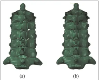
Two FE models of a section of the cervical spine (C2–C7) were built, one using the exact geometry of the section (ASYM model) and another in which the geometry was approximated by assuming symmetry about the mid-sagittal plane of the section (SYM model) (Figure 1). MIMICS (MIMICSÒVersion 14.1; Materialise, Inc., Leuven, Belgium) software package was used for image processing the CT data, IA-FEMESH (University of Iowa, IA, USA) software package was used to generate the FE mesh of the model, and ABAQUS (ABAQUSÒ, Version 6.10-2; Abaqus, Inc., Providence, RI, USA) software package was used for the FE analysis. Lordosis was measured using the four-line Cobb method to be 25° and 22° for the ASYM and SYM models, respectively.
FE model
Vertebrae. The 3D surface geometry of the vertebrae was obtained from CT scans of a 35-year-old man. The exact geometry of the vertebrae was used to construct the ASYM model. The geometry of the vertebrae for SYM model was generated based on the geometry of the ASYM model vertebrae. A mid-sagittal plane was
generated to cut the geometry of the ASYM model. The location of the mid-sagittal plane was calculated based on the average widths of ASYM vertebrae. The width of each vertebra was measured between the left and right outer lateral borders (Figure 2; Table 1).
For each vertebra, the outermost layer (approxi-mately 0.5-mm thick) was assigned cortical bone prop-erties, whereas the rest was assigned cancellous bone properties. The layer of element adjacent to the disk was assigned the material property of the bony
Figure 1. The finite element models: (a) asymmetric (ASYM) model and (b) symmetric (SYM) model.
Figure 2. Circular mesh pattern, which was implemented on the C4 vertebral body: (a) ASYM model and (b) SYM model.
endplate. The isotropic elastic constitutive model was used to simulate the material properties of all elements in vertebrae with approximate thickness of 0.6 mm. Facet joints. Facet joints in each segment of the spine were simulated with 3D GAPUNI element library in ABAQUS. These elements transfer the force between nodes in a single direction as a function of the specified gap between them. The ‘‘softened contact’’ parameter, in ABAQUS, was used to adjust the force exponen-tially across the joint depending on the size of the gap. In each model, the same number of elements was used in each segment. For the SYM model, orientation of each element was the same on the each side of the mid-sagittal plane.
Intervertebral disks. Between each pair of vertebrae, 3D volumes were created to represent the geometry of an intervertebral disk. For the SYM model, the geometry of each disk was created by cutting its geometry in the ASYM model about the mid-sagittal plane. For each disk, the FE mesh comprised two parts: a mesh with a circular pattern representing the annulus fibrosus con-taining the fibers oriented at 625° to the horizontal (as given in the literature) and a mesh in the core, repre-senting the nucleus pulposus (NP). In each model, the same number of layers of elements (six layers) was gen-erated for defining the annulus.
The layers of the annulus fibrosus were simulated with Neo-Hookean hyperelastic constitutive model. For each disk, the Rebar option, in ABAQUS, was used to simulate the behavior of fibers in the annulus. The ‘‘no compression’’ option, in ABAQUS, was used to allow the fibers to undergo only tension loading. For the fibers, isotropic elastic constitutive model was used. The fibers were oriented at 625° to the horizon-tal according to the literature in the cervical region. Incompressible fluid elements were used to simulate fluid behavior of the nucleus.
Ligaments. In each model, five of the ligaments in the cervical spine were modeled, namely, anterior longitu-dinal ligament (ALL), posterior longitulongitu-dinal ligament (PLL), ligamentum flavum (LF), capsular ligament (CL), and interspinous ligament (ISL). For each liga-ment, its point of origin and insertion in the spine
section were taken from literature studies. For the SYM model, each of the ligaments was added to one side before mirroring about mid-sagittal plane. For the FE mesh, truss elements were used for each of the liga-ments, with each element being assigned a cross-sectional area such that the total number of elements would produce the total area, as stated in literature reports. For each model, the same number of elements was used for a given ligament.
Each ligament was taken to be nonlinear elastic behavior, with low stiffness at low strain and higher stiffness at higher strain. The nonlinear behavior of the ligaments was simulated with ‘‘hypoelastic’’ constitutive model. This material model allowed axial stiffness to be defined as a function of axial strain.
For each of the tissues, the same values of material properties were used in both models, and these values were taken from the literature (Table 2).
Loadings and boundary conditions
In each model, the bottom of the inferior endplate at C7 was fixed in all positions and directions and the loading was applied to a flying node (FN) that was cre-ated on the top of the odontoid process of the C2 ver-tebral body. These nodes were fixed in all positions and directions. For each model, a pure moment (each of magnitude 1 Nm) was applied individually in each of the three main directions: extension (EXT), flexion (FLEX), right lateral bending (RLB), and right axial rotation (RAR).
Under each of the applied loadings, the output para-meters obtained were range of motion (ROM), IDP, and facet load (FL) at each of the segments in the model. Validation was done by comparing the ROM results obtained from the FE analysis on the ASYM model,9under each of the four types of applied load-ing, with corresponding ones obtained from a number of in vitro biomechanical studies.10–12
Results
In a previous report,9it was shown that ASYM model was validated. The ASYM model underestimates ROM in 45% of the sets (9 out of 20 sets), with this underesti-mation being (1) consistent when RLB was applied and (2) the largest (25%) at C2–C3 under RAR (Figure 3).
Table 1. Comparison between the measured widths of the vertebrae (in mm), obtained using the asymmetric (ASYM) and symmetric (SYM) models.
C2 C3 C4 C5 C6 C7
ASYM 65.6 63.5 66.5 68.4 70.0 96.4
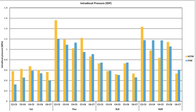
The ASYM model underestimates IDP in 60% of the sets (12 out of 20 sets), with this underestimation being (1) consistent when EXT was applied and (2) the larg-est (50%) at C2–C3 under EXT (Figure 4). The ASYM model underestimates FL in 40% of the sets (6 out of 15 sets), with the largest underestimate being ~75% at C5–C6 under RAR (Figure 5).
Discussion
An FE model of the cervical spine can be constructed based on the exact geometry or using an assumption in the geometry. Symmetry about the mid-sagittal plane is one of the widely used assumptions in FE models of the cervical spine. On the other hand, understanding
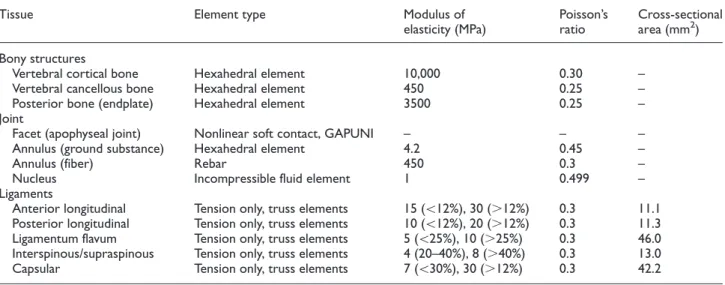
Table 2. Element type and properties of the tissues in the model.5,6
Tissue Element type Modulus of
elasticity (MPa) Poisson’s ratio Cross-sectional area (mm2) Bony structures
Vertebral cortical bone Hexahedral element 10,000 0.30 –
Vertebral cancellous bone Hexahedral element 450 0.25 –
Posterior bone (endplate) Hexahedral element 3500 0.25 –
Joint
Facet (apophyseal joint) Nonlinear soft contact, GAPUNI – – –
Annulus (ground substance) Hexahedral element 4.2 0.45 –
Annulus (fiber) Rebar 450 0.3 –
Nucleus Incompressible fluid element 1 0.499 –
Ligaments
Anterior longitudinal Tension only, truss elements 15 (\12%), 30 (.12%) 0.3 11.1
Posterior longitudinal Tension only, truss elements 10 (\12%), 20 (.12%) 0.3 11.3
Ligamentum flavum Tension only, truss elements 5 (\25%), 10 (.25%) 0.3 46.0
Interspinous/supraspinous Tension only, truss elements 4 (20–40%), 8 (.40%) 0.3 13.0
Capsular Tension only, truss elements 7 (\30%), 30 (.12%) 0.3 42.2
the effect of such an assumption, that is, symmetry in the mid-sagittal plane, is of high importance to trust on the output of the FE model. The lack of such a study
was the motivation for this work, which was an investi-gation of the influence of the method used to construct the solid model of a cervical spine section (exact
Figure 4. Summary of the intradiskal pressure results.
geometry vs assumption of symmetry) on biomechani-cal responses of the model.
Each of the biomechanical responses determined in this work is clinically relevant. ROM indicates the ease with each a person can perform various activities of daily living, such as reading and combing of hair. IDP and FL are measures of load sharing by a segment dur-ing performance of these activities.
For each of the biomechanical outputs determined, the difference in results obtained when ASYM model was used compared to the case when SYM model was used was, on the whole, marginal. Assumption of sym-metry about the mid-sagittal plane reduces the time for constructing the FE model of the cervical spine. Therefore, the time spent on creating the hexahedral mesh on the SYM model becomes approximately half of the ASYM model due to complexity in the cervical spine geometry. However, in this work, the number of nodes and elements in the SYM model was higher than in the ASYM model; as such, the simulation time for the former model was longer.
This study has three limitations. First, the solid model was constructed using CT scans from one patient. Thus, the results are patient-specific. Second, the bony tissues, annulus fibrosus, and NP were each modeled as isotropic, elastic materials. Use of sophisti-cated material constitutive models, such as transverse isotropy for cortical bone, poroelasticity for cancellous bone, and hyperelasticity for NP, could have enhanced the FE analysis. Third, muscles were not included in the solid model, and left lateral bending moment and left axial rotation loadings were not applied; in each of the loadings, a compressive load representing the weight of the head was not included. Addition of each of these features would have further enhanced the analysis.
Conclusion
For a model of a section of the cervical spine (C2–C7), FE analysis results obtained from imposing a series of clinically relevant applied loadings (EXT, FLEX, RLB, and RAR) on the model, each of magnitude 1 Nm, show that the influence of the method used to build the 3D solid model (exact reconstruction of geometry vs reconstruction of geometry that assumed symmetry about the mid-sagittal plane of the section) was, on the whole, moderate.
Declaration of conflicting interests
The author(s) declared no potential conflicts of interest with respect to the research, authorship, and/or publication of this article.
Funding
The author(s) received no financial support for the research, authorship, and/or publication of this article.
References
1. Panjabi MM. Cervical spine models for biomechanical research. Spine 1998; 23: 2684–2699.
2. Yoganandan N, Kumaresan S, Voo L, et al. Finite ele-ment modeling of the C4-C6 cervical spine unit. Med Eng Phys1996; 18: 569–574.
3. Clausen JD, Goel VK, Traynelis VC, et al. Uncinate pro-cess and Luschka joints influence the biomechanics of cervical spine: quantification using a finite element model of the C4-C5 segment. J Orthop Res 1997; 15: 342–347. 4. Panzer MB and Cronin DS. C4-C5 segment finite
ele-ment model developele-ment, validation, and load-sharing investigation. J Biomech 2009; 42: 480–490.
5. Zhang QH, Teo E-C, Ng H-W, et al. Finite element anal-ysis of moment-rotation relationships for human cervical spine. J Biomech 2006; 39: 189–193.
6. Goel VK and Clausen JD. Prediction of load sharing among spinal components of a C5-C6 motion segment using finite element approach. Spine 1998; 23: 684–691. 7. Kallemeyn N, Gandhi A, Kode S, et al. Validation of a
C2-C7 cervical spine finite element model using specimen-specific flexibility data. Med Eng Phys 2010; 32: 482–489.
8. Del Palomar AP, Calvo B and Doblare´ M. An accurate finite element model of the cervical spine under quasi-static loading. J Biomech 2008; 41: 523–531.
9. Erbulut DU, Zafarparandeh I, Lazoglu I, et al. Applica-tion of an asymmetric finite element model of the C2-T1 cervical spine for evaluating the role of soft tissues in sta-bility. Med Eng Phys 2014; 36: 915–921.
10. Wheeldon JA, Pintar FA, Knowles S, et al. Experimental flexion/extension data corridors for validation of finite element models of the young, normal cervical spine. J Biomech2006; 39: 375–380.
11. Nightingale RW, Carol Chancey V, Ottaviano D, et al. Flexion and extension structural properties and strengths for male cervical spine segments. J Biomech 2007; 40: 535–542.
12. Nightingale RW, Winkelstein BA, Knaub KE, et al. Comparative strengths and structural properties of the upper and lower cervical spine in flexion and extension. J Biomech2002; 35: 725–732.