Adaptive OFDM Modulation for Underwater Acoustic
Communications: Design Considerations and
Experimental Results
Andreja Radosevic, Student Member, IEEE, Rameez Ahmed, Tolga M. Duman, Fellow, IEEE,
John G. Proakis, Life Fellow, IEEE, and Milica Stojanovic, Fellow, IEEE
Abstract—In this paper, we explore design aspects of adaptive
modulation based on orthogonal frequency-division multiplexing (OFDM) for underwater acoustic (UWA) communications, and study its performance using real-time at-sea experiments. Our design criterion is to maximize the system throughput under a target average bit error rate (BER). We consider two different schemes based on the level of adaptivity: in the first scheme, only the modulation levels are adjusted while the power is allocated uniformly across the subcarriers, whereas in the second scheme, both the modulation levels and the power are adjusted adaptively. For both schemes we linearly predict the channel one travel time ahead so as to improve the performance in the presence of a long propagation delay. The system design assumes a feedback link from the receiver that is exploited in two forms: one that conveys the modulation alphabet and quantized power levels to be used for each subcarrier, and the other that conveys a quantized estimate of the sparse channel impulse response. The second approach is shown to be advantageous, as it requires significantly fewer feedback bits for the same system throughput. The effectiveness of the proposed adaptive schemes is demonstrated using computer simulations, real channel measurements recorded in shallow water off the western coast of Kauai, HI, USA, in June 2008, and real-time at-sea experiments conducted at the same location in July 2011. We note that this is the first paper that presents adaptive modulation results for UWA links with real-time at-sea experiments.
Index Terms—Adaptive modulation, feedback, orthogonal
frequency-division multiplexing (OFDM), underwater acoustic (UWA) communication.
Manuscript received February 26, 2012; revised October 17, 2012 and Feb-ruary 12, 2013; accepted March 12, 2013. Date of publication May 24, 2013; date of current version April 10, 2014. This work was supported by the Multidis-ciplinary University Research Initiative (MURI) of the U.S. Office of Naval Re-search (ONR) under Grants N00014-07-1-0738/0739, N00014-10-1-0576, and N00014-09-1-0700.
Associate Editor: S. Zhou.
A. Radosevic is with Qualcomm Technologies Inc., San Diego, CA 92122 USA (e-mail: [email protected]).
R. Ahmed and M. Stojanovic are with the Department of Electrical and Com-puter Engineering, Northeastern University, Boston, MA 02115 USA (e-mail: [email protected]; [email protected]).
T. M. Duman is with the Department of Electrical and Electronics En-gineering, Bilkent University, Bilkent, Ankara 06800, Turkey (e-mail: [email protected]).
J. G. Proakis is with the Department of Electrical and Computer Engi-neering, University of California at San Diego, La Jolla, CA 92093 USA (e-mail: [email protected]).
Color versions of one or more of the figures in this paper are available online at http://ieeexplore.ieee.org.
Digital Object Identifier 10.1109/JOE.2013.2253212
I. INTRODUCTION
U
NDERWATER ACOUSTIC (UWA) channels are con-sidered as some of the most challenging communication media, generally characterized by low propagation speed of sound in water (nominally 1500 m/s), limited bandwidth, and randomly time-varying multipath propagation which results in frequency-selective fading [1]. Delay spreading in an UWA channel can occur over tens of milliseconds; however, the channel impulse response often has a sparse structure, with only a few propagation paths carrying most of the channel energy.Orthogonal frequency-division multiplexing (OFDM) has re-cently emerged as a promising alternative to single-carrier sys-tems for UWA communications because of its robustness to channels that exhibit long delay spreads and frequency selec-tivity [2]–[14]. However, applying OFDM to UWA channels is a challenging task because of its sensitivity to frequency offset that arises due to motion. In particular, because of the low speed of sound and the fact that acoustic communication signals oc-cupy a bandwidth that is not negligible with respect to the center frequency, motion-induced Doppler effects result in major prob-lems such as nonuniform frequency shift across the signal band-width and intercarrier interference (ICI) [15], [16].
Time-varying multipath propagation and limited bandwidth place significant constraints on the achievable throughput of UWA communication systems. To support high spectral efficiencies over long intervals of time in a nonstationary environment such as the UWA channel, we consider commu-nication systems employing adaptive modulation schemes. While adaptive signaling techniques have been extensively studied for radio channels [17]–[21], only preliminary results for UWA channels are reported in [22]–[26], where simulations and recorded data are used to demonstrate the effectiveness of the proposed adaptation metrics.
The performance of an adaptive system depends on the trans-mitter’s knowledge of the channel which is provided via feed-back from the receiver. Since sound propagates at a very low speed, the design and implementation of an adaptive system es-sentially relies on the ability to predict the channel at least one travel time ahead. This is a very challenging task for communi-cations in the range of several kilometers which imposes signifi-cant limitations on the use of feedback. However, our prior work has shown that channel prediction is possible over such intervals of time using a low-order predictor [27]. Crucial to successful
0364-9059 © 2013 IEEE. Personal use is permitted, but republication/redistribution requires IEEE permission. See http://www.ieee.org/publications_standards/publications/rights/index.html for more information.
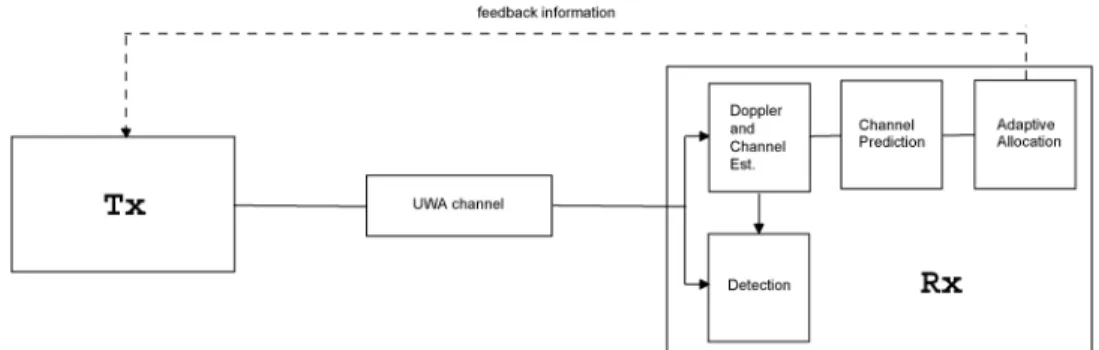
Fig. 1. The adaptive system with the important functional blocks.
channel prediction is motion compensation that stabilizes the nonuniform Doppler shift and enables (sparse) channel estima-tion. The so-obtained channel estimates contain only a few sig-nificant coefficients that are shown to be stable enough to sup-port prediction several seconds into the future.
In this paper, we design an adaptive OFDM system and study its performance using recorded test channels and real-time at-sea experiments. Our approach and contributions are the following.
• We estimate small Doppler rates (less than 10 ) that cor-respond either to drifting of the instruments, or residuals after initial resampling in mobile systems (e.g., systems using autonomous underwater vehicles). Proper Doppler compensation ensures stability over intervals of time that are long enough to support channel prediction several sec-onds ahead.
• We exploit the sparse multipath structure of the channel impulse response to estimate the most significant channel paths and simplify the prediction problem. Specifically, we estimate only a few significant paths of the channel within a possibly large overall delay spread. We treat the statistical properties of the underlying random process of the channel fading as unknown, and compute the parameters of a linear predictor adaptively, by applying a recursive least squares (RLS) algorithm [28].
• We develop two modulation schemes, distinguished by the level of adaptivity: Scheme 1 adjusts only the modula-tion level and assumes a uniform power allocamodula-tion, while scheme 2 adjusts both the modulation level and the power allotted to each subcarrier. Both schemes are based on a greedy algorithm whose optimality was discussed in [20]. • We propose a new design criterion for an adaptive OFDM system based on the information that is fed back to the transmitter. Specifically, we consider two cases. In the first case, the information about the modulation alphabet and the quantized power level for each subcarrier is computed at the receiver and fed back to the transmitter. In the second case, the quantized channel estimates are fed back, and the adaptive algorithm for bit loading and power allocation is implemented at the transmitter.
• We demonstrate the effectiveness of the proposed adap-tive schemes using computer simulations, test channels recorded during the Kauai Acoustic Communications Mul-tidisciplinary University Research Initiative (MURI) 2008 (KAM08) experiment in shallow water off the western
coast of Kauai, HI, USA, in June 2008, and real-time at-sea experiments conducted during the Kauai Acoustic Com-munications MURI 2011 (KAM11) experiment at the same location in July 2011. The numerical and experimental re-sults show that the adaptive modulation scheme can pro-vide significant throughput improvements as compared to conventional, nonadaptive modulation for the same power and target bit error rate (BER).
The paper is organized as follows. In Section II, we describe the system and the channel model that characterizes an UWA channel. In Section III, we introduce a linear RLS predictor for the channel tap coefficients. In Section IV, we introduce the rules for selection of the modulation levels, the information that is fed back to the transmitter, and the adaptive OFDM schemes. In Section V, we demonstrate the performance of the proposed adaptive schemes using numerical and experimental results that are based on recorded test channels and real-time at-sea trials, respectively. In Section VI, we provide concluding remarks.
II. SYSTEM ANDCHANNELMODEL
Let us consider an OFDM system with subcarriers, where the th block of the input data symbols ,
, is modulated using the inverse fast Fourier transform (IFFT). The block of input data consists of information-bearing sym-bols and pilots, with corresponding sets denoted as and , respectively. We assume that the information symbols are inde-pendent, while candidate modulation schemes are binary phase-shift keying (BPSK), quadrature phase-phase-shift keying (QPSK), 8 phase-shift keying (8PSK), and 16-quadrature amplitude mod-ulation (16QAM) with 2-D Gray mapping. In other words, for the th subcarrier, where , and the th block, the modu-lation level , and if no data are transmitted . It is assumed that the pilot symbols take values from the QPSK modulation alphabet. For each modula-tion alphabet, we assume a uniform distribumodula-tion of the constel-lation points with a normalized average power. The transmitter sends frames of OFDM blocks, such that one OFDM block oc-cupies an interval , where and are the symbol duration and the guard time interval, respectively. We denote by the total bandwidth of the system, by the fre-quency of the first subcarrier, by the central frequency, and by the subcarrier separation.
In this paper, we consider an adaptive system illustrated in Fig. 1. The different functional blocks of the system, such as channel and Doppler estimation, channel prediction, adaptive
allocation, and feedback information, are discussed in the rest of the paper.
A. Channel Model
Let us now define the impulse response of the overall channel (1) where is the number of distinct propagation paths, is the delay variable, and is the time at which the channel is ob-served. Coefficient represents the real-valued gain of the th path, and represents the corresponding delay. Here, we emphasize that the channel model (1) includes the initial re-sampling operation at the receiver by a common Doppler factor. Assuming a high bandwidth (sufficient resolution in the delay variable ), the set of coefficients offers a good representation of the actual propagation paths. The re-ceived signal is given as
(2) where is the transmitted signal and represents the ad-ditive white Gaussian noise (AWGN) process with zero mean and power spectral density normalized to unity.1If we also de-fine the equivalent baseband signals and with respect to the frequency , such that
(3) we then obtain
(4) where
(5) and is the equivalent baseband noise. Equation (4) implies the equivalent baseband channel response
(6)
B. Modeling of the Time-Varying Path Delay
Following the approach from our previous work [27], we model the time-varying path delays as
(7)
1The AWGN assumption incurs no loss of generality of the proposed adaptive
scheme even though acoustic noise is not white.
where is the Doppler scaling factor, which is some func-tion of time. This model includes the fixed term , which describes the nominal propagation delay corresponding to the system geometry at the time of transmission, and an additional term that describes the effect of motion at the time of observation either due to drifting of the instruments (Doppler rates less than 10 ) in stationary systems, or residuals after initial resampling in mobile systems (e.g., systems using au-tonomous underwater vehicles). The system motion during a period of time corresponding to a few seconds (or several data packets) is modeled by velocity and acceleration terms which lead to a linear Doppler rate . A more accurate model could include higher order terms; however, experimental results con-firm that this is not necessary. Specifically, we model as a piecewise linear function
(8) where , and are the Doppler scaling factors evaluated at time instances .
This channel model is deemed suitable for the time scales of interest to an adaptive UWA communication system, since pro-viding a reliable predicted channel state information (CSI) de-pends on the availability of a stable signal reference that can be obtained through accurate motion compensation. For example, for a 2-km link and the center frequency 20 kHz, a small Doppler rate can cause the phase of in (5) to change up to radians during a time interval of 1.33 s that corresponds to the propagation delay of one travel time.2 Such a phase shift can considerably degrade the performance of channel prediction and the reliability of the corresponding CSI. In other words, proper Doppler compensation ensures stability over intervals of time that are long enough to support channel prediction several seconds ahead.
Model (7) allows one to decouple phase into two terms: one that is not related to motion, and another that is re-lated to motion. While the first term may not be predictable with sufficient accuracy because frequency may be several orders of magnitude larger than the inverse of the path delay, the second term can be predicted using the estimates of the Doppler scaling factors . With this fact in mind, we proceed to develop a channel prediction method that focuses on two general terms: a complex-valued coefficient and a mo-tion-induced phase . In other words, we model the baseband channel response as
(9) where we treat each as an unknown complex-valued channel coefficient, which is assumed to be stable over a prolonged period of time (tens of seconds), and as an unknown motion-induced phase, which is modeled as a second-order polynomial based on expressions (7) and (8). We
2Here we should make a distinction between making the prediction for one
travel time ahead, and for the round-trip time (two travel times ahead), since the two cases correspond to different feedback implementation strategies, i.e., different functions performed by the two ends of a link.
Fig. 2. Channel estimates obtained by the RLS and the MP algorithm.
emphasize that this model is valid for some interval of time, but its parameters may change from one such interval to another.
Our goal is to develop a two-step procedure in which we first estimate the channel coefficients at the receiver from a probe signal, and then use the so-obtained estimates to form predic-tions, which are finally fed back to the transmitter. This CSI will be used at the receiver (or the transmitter) to perform adaptive allocation of the modulation levels and power for each subcar-rier in the current OFDM block transmission.
C. Channel Estimation
Channel estimation consists of two steps. In the first step, initial phase compensation is performed to produce a stable reference signal. This step includes resampling by a nominal (average) Doppler factor and removal of the phase offset . Here, we should emphasize that the process relies on the esti-mates of the Doppler scaling factors , which are assumed to be available with a certain precision (e.g., from a dedicated synchronization preamble). In the second step, the so-obtained signal is used to estimate the path coefficients . The Doppler factors are not needed thereafter, as we conjecture that the channel coefficients after motion compensation exhibit sufficient stability to allow prediction several seconds into the future.
Fig. 2 illustrates the channel estimates obtained from real data collected during the KAM08 experiment. Specifically, in this section, we will focus on channel estimates obtained from a short probe signal described in [29]. After the initial phase compensation where a phase-locked loop (PLL) was used, we perform channel estimation from the received signal using the matching pursuit (MP) algorithm [30]. Note from Fig. 2 that the MP algorithm produces eight coefficients, where neighboring coefficients belong to the same propagation path due to the path dispersion [1]. For further analysis, we weigh the adjacent coefficients based on the channel tap power and merge them, so as to represent the channel via four propagation paths , , , and . Therefore, the MP algorithm provides estimates of the channel coefficients , assuming that channel coefficients are sufficient for the description of the sparse multipath structure. These estimates are denoted by
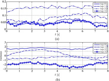
Fig. 3. (a) Magnitudes and (b) phases of the channel path coefficients.
, and computed at time instances separated by 155 ms. For comparison purposes, we also provide the channel estimate obtained using the RLS algorithm. Different peaks in the channel estimates can be associated with multiple surface and bottom reflections calculated from the geometry of the experiment. As can be seen from the figure, the MP algorithm successfully estimates the significant channel coefficients, and reduces the estimation error with respect to that incurred by the RLS algorithm.
We emphasize that positions of the significant paths may drift on a larger time scale (tens of seconds), and, therefore, have to be updated accordingly. In Fig. 3, we show the magnitudes and phases of the significant paths over a time period of 8 s. As we initially conjectured, the phases of remain relatively stable for more than a few seconds (a propagation delay over several kilometers).
III. CHANNELPREDICTION
As we previously reported in [27], the future values of are predicted from the estimates . In particular, if the OFDM blocks are periodically transmitted at time instances , we use observations made at times to predict the channel at time . To account for possible correlation between the path coefficients, we allow for their joint prediction. In other words, we use all channel coefficients to predict each new coefficient. The prediction is thus made as
(10) where
(11)
(12) Matrix contains prediction coefficients that are to be determined.
Table I
PREDICTIONRLS ALGORITHM
Because the second-order statistics are not available for the random process , we compute adaptively, by ap-plying the RLS algorithm as specified in Table I. In (14), is an matrix, which represents an estimate of the in-verse joint autocorrelation matrix and is a small constant, typically a fraction of the minimum among vari-ances of the channel coefficients jointly predicted by the RLS algorithm.
As discussed earlier, UWA systems suffer from inherently long propagation delays, which pose additional challenges in the design of a predictor. To counteract this problem, channel prediction one travel time ahead is achieved by using an RLS predictor of a low-order (e.g., or ) and a small forgetting factor [e.g., , which corresponds to
an effective window of length ].
Note that the forgetting factor is uniquely specified for all channel coefficients. With a small order and only a few sig-nificant paths, i.e., a small , computational complexity of joint channel prediction is sufficiently low to allow for a practical im-plementation.
The structure of matrix is primarily driven by the ge-ometry of the propagation environment, i.e., not all of the prop-agation paths are mutually correlated. In the present data set, the strongest arrival often exhibits more stability, and the con-tribution from the other, weaker paths in its prediction appears to be negligible. Therefore, the strongest path can be predicted independently, without loss in performance. In other words, if channel coefficient corresponds to the strongest path, (18) can be modified as follows: the th column of is recursively updated only for those elements that correspond to the prior ob-servations of the th coefficient
. In addition, exploiting the correlation among the re-maining paths may lead to a performance improvement, whose exact amount is determined by the environmental profile, and accuracy of the channel and Doppler estimates.
After performing channel prediction at the receiver, the so-obtained CSI is used to initialize adaptive allocation of the modulation levels and power across the OFDM subcarriers. As we will discuss later, depending on which end of the com-munication link performs adaptive allocation, different types of information are fed back over a low-rate feedback channel. In the following, we describe the design framework, initially
proposed in [26], under which we developed two practical adaptive modulation schemes, and we also discuss the design of bandlimited feedback.
IV. ADAPTIVEMODULATION ANDPOWERALLOCATION
The system model assumes that residual Doppler effects are negligible after proper initial motion compensation [resampling by a nominal Doppler factor and removal of the phase offset ]. After this initial step, it is also assumed that the channel is constant at least over the transmission interval of one OFDM block. Therefore, the received signal can be expressed as
(20) where
(21)
and , , and are, respectively, the received signal after fast Fourier transform (FFT) demodulation, the transmitted power, and zero-mean circularly symmetric complex AWGN with variance per dimension. The noise term includes the effects of ambient noise and residual ICI on the th subcarrier and the th OFDM block, which is approximated as a Gaussian random variable.
For the transmission of each OFDM block, we adaptively compute the size of the modulation alphabet and the transmission power . The objective of our adaptive OFDM system is to maximize the throughput by maintaining a target average BER. To maintain the BER at a fixed value, we propose the following optimization criterion:
maximize subject to
(22) where is the overall average power allocated to the th OFDM block, is the average BER for the th subcarrier, and is the target average BER. The average power can be expressed as where is a constant and is the residual power from the previous block which was not allocated (i.e., is less than the minimum power increment required by the algorithm for a one-bit increase of the overall throughput). Here, we should emphasize the difference be-tween total power allocation and distribution of this total power among the subcarriers. In the former case, one can design an adaptive scheme where the total power is adaptively allocated (and uniformly distributed among the subcarriers) to achieve the prespecified performance [e.g., the target average BER or signal-to-noise (SNR) at the receiver] for the fixed system throughput, whereas in the latter case, the fixed total
power is nonuniformly distributed among the subcarriers to achieve the prespecified performance, and to maximize the system throughput. For the purpose of experimental sea trials, the total power allocation is initially set to a value which is able to support the target error rate, and avoid the outage scenario (no data transmission).
To reduce the computational complexity of the adaptive algo-rithm, the subcarriers of the th OFDM block can be grouped into clusters. If we assume , we group consecutive sub-carriers into clusters, where is the size of each cluster. We denote by and , respectively, the allocated power and the modulation level corresponding to the th cluster, . The optimal power level for each cluster depends on the transfer function of the channel. If the channel does not change much within a cluster, computation of and is performed based on the average channel gain in cluster . Note that if a cluster is affected by a deep fade, it will be dominated by the subcarrier with the lowest channel gain. Clustering reduces the computational load (see [26] for more details), but implies possible error penalization and/or a decrease in throughput as compared to the full computation of modulation levels and powers for all subcarriers.
A. Thresholds for Modulation Levels
Due to the large propagation delays, the proposed adaptive OFDM transmission relies on channel prediction. We obtain predictions of the channel gains one travel time ahead based on the time-domain predictions of the most significant channel coefficients (10). We model the prediction error on the th channel path as a complex zero-mean circularly symmetric Gaussian random variable with variance per dimension. Furthermore, based on the a priori knowledge obtained from the channel prediction, we model as a complex Gaussian random variable with mean
(23)
and variance , where is the number of sig-nificant time-domain channel coefficients. Assuming that the current channel gain is perfectly known, we apply max-imum likelihood symbol detection for the AWGN channel at the output of the matched filter. Thus, the probability of bit error for the th subcarrier for M-ary phase-shift keying (MPSK)/mul-tiple quadrature amplitude modulation (MQAM) is well approx-imated by [18]
(24) where coefficients are determined numerically for each modulation alphabet, as accurately as desired for the BER approximation and take values for
, respectively.
For transmission of the th OFDM block, the adaptive system has knowledge of the predicted values , but not of the full
channel . Therefore, from (24), the average BER on the th subcarrier is obtained as [18]
(25) For a given target , we now compute the thresholds for the available modulation levels. The solution for is given by
(26) where is the principal branch of the Lambert -function, the inverse function of . Note that if , the threshold goes to zero, i.e., . This case corresponds either to high SNR regimes with reliable CSI, or to very high target BERs of the system. Reasonably accurate approximations for , which can be computed efficiently, are provided in [31]. We should emphasize that different thresholds correspond to different av-erage values of , since all of the subcarriers are affected by the prediction error of the same variance .
The optimization problem (22) is hard to solve from the standpoint of a practical implementation, because it is com-putationally too intensive to be run at the receiver (or the transmitter) for every OFDM block. Therefore, we pursue suboptimal solutions which are obtained by relaxing one of the problem constraints. Specifically, we focus on two adaptive schemes in the rest of this section.
B. Adaptive Scheme 1
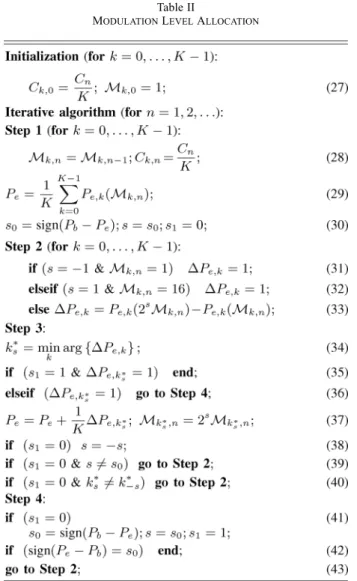
The optimal solution for (22) includes a nonuniform power allocation for a maximum attainable throughput, such that the target average BER is . This causes that each subcarrier con-tributes to the average BER differently, due to the frequency se-lectivity of the channel. However, the problem can be simplified if we consider adaptive allocation of the modulation levels while distributing the power uniformly among the subcarriers. Since we adaptively allocate only the modulation levels, the so-ob-tained solution for (22) will be suboptimal. Specifically, we apply a greedy algorithm that computes the modulation levels in a given block using the allocations from the previous block for initialization. The proposed algorithm is given in
Table II
MODULATIONLEVELALLOCATION
Table II. Similar greedy algorithms have already been consid-ered in [32] and [33].
After initialization of the algorithm for each subcarrier, as given by (27)–(30), we successively increase the modulation levels for those subcarriers that require the smallest power in-crement (31)–(43), while maintaining the average BER below the target . If the set of modulation levels from the previous transmission interval is not a greedy-based solution for the cur-rently available CSI , the algorithm greedily searches for the closest solution which is used as a new initialization point of the algorithm. Also, if the algorithm does not support the throughput from the previous transmission interval (i.e., it fails during the initialization step), it searches for the subcarrier with the largest power decrement that is required to decrease the modulation level . The algorithm is terminated when the prespecified is achieved.
C. Adaptive Scheme 2
In the second scheme, we consider adaptive allocation of the modulation levels and the subcarrier powers such that
for each subcarrier.
Once the thresholds are computed from (26), we apply the adaptive algorithm of Table III to generate the signal of the th
OFDM block. The algorithm is terminated when the available power is exhausted, or when all subcarriers achieve the max-imum modulation level (16QAM). Here, we emphasize that for those subcarriers that are in a deep fade no data are transmitted (zero power is allocated). In other words, the subcarrier with index is in deep fade if threshold is high enough to violate the power constraint in (22).
Because of the additional freedom to adjust the power, this scheme will achieve a higher overall throughput as compared to scheme 1.
D. Limited Feedback for Adaptive UWA Systems
We assume that a limited-feedback channel is available for conveying information from the receiver back to the transmitter. The receiver has knowledge of the channel frequency response at subcarrier frequencies and the corresponding channel im-pulse response. The transmitter needs to know the modulation levels and the power levels at the frequencies. To accomplish this, there are different feedback options. Here we consider three different alternatives.
A first option is to feed back the frequency response at the subcarriers, where is typically of the order of 1000. If the channel frequency response changes slowly across frequencies, neighboring subcarriers would be allocated the same modula-tion and power levels. In such a case, it is not necessary to feed back the channel frequency response in amplitude and phase for each subcarrier. Hence, the total number of bits fed back can be reduced from a factor of to some factor, say , where is the number of subcarriers contained in the coher-ence bandwidth of the channel.
A second option is to transmit the actual modulation levels and the power levels directly to the transmitter at the subcar-rier frequencies. bits may be used to represent the available modulation levels. For example, in our case, we used
bits. The power levels can be uniformly quantized, such that bits are used to represent each quantization level.
A third option is to feed back the values of the quantized channel impulse response. Since the impulse response is sparse, the total number of bits required to convey this information to the transmitter is , where is the number of sig-nificant coefficients in the channel impulse response (typically,
or less for the shallow-water channels considered), is the number of bits required to represent the quantized com-plex-valued channel coefficients, and is the number of bits required to represent the time delay of each dominant channel coefficient.
To further reduce the number of bits fed back to the trans-mitter, we applied a lossless data compression technique. In par-ticular, we employed run length encoding (RLE) [34], which is a simple coding scheme that provides good compression of data that contains many runs of zeros or ones, together with the well-known Lempel–Ziv–Welch (LZW) algorithm (used as an inner code) [35], to efficiently compress the feedback informa-tion. As we will see in the following section, assuming perfect CSI at the receiver, feeding back the sparse channel impulse re-sponse and computing the modulation levels and power levels at the transmitter requires significantly fewer bits.
Table III
MODULATION ANDPOWERLEVELALLOCATION
V. NUMERICAL ANDEXPERIMENTALRESULTS
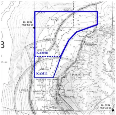
In this section, we present numerical and experimental re-sults on the performance of the proposed adaptive schemes from Section IV. The numerical results are based on channel mea-surements recorded during the KAM08 experiment, and exper-imental results from the real-time at-sea trials that were con-ducted during the KAM11 experiment. Both experiments were conducted at the same location with operational areas marked in Fig. 4.
A. Numerical Results From the KAM08 Experiment
The KAM08 experiment took place in 100-m deep water, with a communication distance of 4 km. The transmitter was de-ployed at the location Sta00 (see Fig. 5) as a 52.5-m aperture ver-tical array of eight ITC-1001 transducers (7.5-m spacing), with a sampling rate of 100 kHz. The receiver was deployed at the location Sta08 as a 56.25-m aperture vertical line array (VLA) of 16 elements (3.75-m spacing), with a sampling rate of 50 kHz. The performance results are based on the channel estimates for transmissions between the fourth trans-ducer from the bottom (49.5 m deep) and the tenth hydrophone from the bottom (65.25 m deep). The total bandwidth and the guard time are 7.8 kHz and 100 ms, respectively. We assume an OFDM transmission with subcarriers and a frequency separation of 15.25 Hz. The target average BER is . We estimate the channel using the MP algorithm, and predict the five significant channel coefficients 2.67 s ahead.
Fig. 4. The KAM08 and KAM11 operational areas are outlined by the dashed and solid lines, respectively.
Fig. 5. Mooring deployment positions during the KAM08 in latitude and lon-gitude. The acoustic source array was located at Sta00, while the VLAs were located at Sta08 and Sta16.
Fig. 6 presents achievable throughput results for the OFDM systems that employ scheme 1 and scheme 2 without clustering for 24 dB, which is measured relative to the overall channel power. We also provide performance results for the nonadaptive scheme (with uniform power and modulation levels) and the optimal solution, which is evaluated using the interior-point method [36] to solve the nonlinear convex opti-mization problem (22). Interestingly, scheme 2 shows a slight performance loss only for the high SNR regime as compared to the optimal solution, while scheme 1 exhibits a performance degradation for the entire SNR region. Both schemes signifi-cantly outperform the nonadaptive solution.
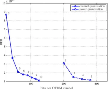
In Fig. 7, we summarize the feedback requirements of scheme 2 without clustering . Feeding back the power and
mod-Fig. 6. Throughput performance of the various schemes considered.
Fig. 7. Performance of limited feedback for scheme 2 with , overall power of 60 dB, and average throughput of 3 b per subcarrier. Numbers on the graph indicate the number of bits that are used to represent the quantized power levels (dashed line), and the real and imaginary parts of each quantized channel coefficient (solid line).
ulation level computed at the receiver clearly requires more bits than feeding back the (sparse) channel response. 2, 3, 4, and 5 b are used to represent the quantized power levels, and 3 b are used to represent the five modulation levels (no transmission, BPSK, QPSK, 8PSK, and 16QAM), resulting in a total of 2560, 3072, 3584, and 4096 b with and . The feedback information is then compressed, as discussed in Section IV, resulting in 201, 245, 294, and 350 b (the values in-dicated on the -axis). If the channel response is fed back, 3, 4, , 10 b are used to represent the real and the imaginary parts of each quantized channel coefficient, and 8 b are used to represent the corresponding delays. The feedback infor-mation is then compressed similarly as in the previous strategy. We note that the minimum number of bits required to maintain the target average BER at 10 is 350 and 120 for the two cases,
Fig. 8. Mooring deployment positions during the KAM11 in latitude and lon-gitude. The VLAs were located at Sta05 and Sta10. The acoustic source array was located at the ship and used when the ship was stationary.
Fig. 9. The geometry and the setup of the adaptive system.
i.e., that feeding back the channel response reduces the feed-back requirements approximately threefold. When clustering is applied, the two feedback strategies require a similar number of bits to feed back; however, clustering is performed at the ex-pense of reducing the overall throughput of scheme 2.
B. Experimental Results From the KAM11 Experiment
The KAM11 experiment took place in 100–120-m-deep water, with communication distances of 1, 2, and 3 km. The transmitter was deployed from the ship as a 1.5-m aperture vertical array of four ITC-1032 transducers (0.5-m spacing) at different locations within the operational area while the ship was stationary. The sampling rate was 100 kHz. The radio-frequency (RF)-coupled receiver was deployed at loca-tions Sta05 and Sta10 (see Fig. 8) as a 0.6-m aperture VLA of four elements (0.2-m spacing), with a sampling rate of
100 kHz. Both the transmitter and the receiver were deployed in the middle of the water column. A feedback from the recorder buoy was provided using an RF link. The geometry of the experiment and the setup of the system are given in Fig. 9. Due to the variations of the channel that are inherently present, and different communication distances tested in the field, a typical SNR at the receiver varied between 2 and 20 dB.
The OFDM frame contains four blocks with sub-carriers per block, at a central frequency of 30 kHz. The re-ceiver operates coherently where 50% of subcarriers are used as pilots to accommodate for real-time testing of the system, since the channel multipath structure can significantly change during an experimental trial (tens of minutes or even hours). Note that such a high overhead will not be required in practice when a propagation model can be run before deployment to evaluate the multipath extent for a given system geometry. The total band-width and the guard time are 10 kHz and 100 ms, respectively. Frame synchronization is performed using a PN sequence of duration 25 ms and the symbol rate 10 ksymb/s. The presented performance results are generated by employing maximal ratio combining (MRC) of signals received at four el-ements. However, we should emphasize that even though MRC is used for data detection, we use only one receive element to perform channel estimation and adaptive allocation to minimize the processing time at the receiver.
The adaptive system is initialized at the transmitter end (a terminal at the ship) by sending activation commands to the re-ceiver end (a terminal at the RF-coupled buoy) through the wiless link. Once a confirmation message is received from the re-ceiver terminal, the transmitter end executes a sequence of op-erations such as acquiring the ship position from a Global Po-sitioning System (GPS), gathering various environmental data, etc. This is followed by the first OFDM frame transmission with a uniform power allocation and QPSK modulation alphabet for all data subcarriers. Once the frame is detected at the receiver, it is stored at the local driver for further processing. In partic-ular, we perform initial synchronization using the PN preamble, which is followed by PLL-based Doppler estimation and com-pensation, as suggested in [15]; we then conduct channel esti-mation over the uniformly spaced pilot grid using the orthogonal matching pursuit (OMP) algorithm [30], and perform coherent detection for each OFDM block of the received frame; finally, using the channel estimates, we execute scheme 2 at the receiver to compute the power and modulation levels, which are then fed back to the transmitter and used for the next OFDM frame trans-mission. During each real-time trial, we transmitted between 30 and 50 consecutive OFDM frames to demonstrate the perfor-mance of the proposed adaptive scheme, and the functionality of the implemented system.
Among various constraints on the real-time implementation of the system (e.g., out-of-band interference from the other sys-tems simultaneously tested, a weak RF link for certain positions of the ship, weather conditions, etc.), the most important limita-tion is determined to be the total round-trip time of the system that was on the order of 10–20 s. This significant delay was mainly caused by all-level processing at both sides of the link (acquiring GPS and environmental data before each transmis-sion and after each reception, frame acquisition, recording, data processing including prediction and adaptive allocation, etc.), while physical propagation contributed with delays of 0.67–2 s. Note that the RF feedback imposes no significant delay in the system, and the total round-trip time is mainly determined by high processing delays. Since these delays were on the order of several seconds, a good performance of the proposed schemes is expected for channels whose coherence time sits within this
Fig. 10. Channel estimates from initial frame synchronization preamble for three consecutive nonadaptive OFDM frame transmissions. The average time interval between two consecutive frame transmissions is (roughly) 20 s.
interval. In contrast, for rapidly varying channels, high pro-cessing delays will result in a poor performance of channel pre-diction and outdated CSI (which can be seen as feedback error). Here, we should emphasize that the ultimate performance limi-tation of an adaptive UWA system will not be determined by the processing delay, but by the physical propagation delay, which gives a lower bound on the channel coherence time that can be supported.
As discussed in Sections II and III, some channel measure-ments indicated that the channel coherence time was 3–4 s (or more), which allowed us to perform channel prediction and minimize feedback errors. These conditions notably prevailed during sea trials when the channel conditions were calm (e.g., wind speed of 2–8 kn and Doppler rates of 10 ), while higher wind speeds usually coincided with reduced coherence time. In the rest of this section, we will focus on the experimental results obtained from calmer sea trials with the (average) channel coherence time on the order of seconds. We note that channel conditions in general may not be so calm, resulting in a proportional reduction of coherence times that can severely limit the performance of our adaptive scheme.
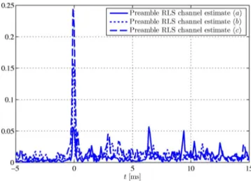
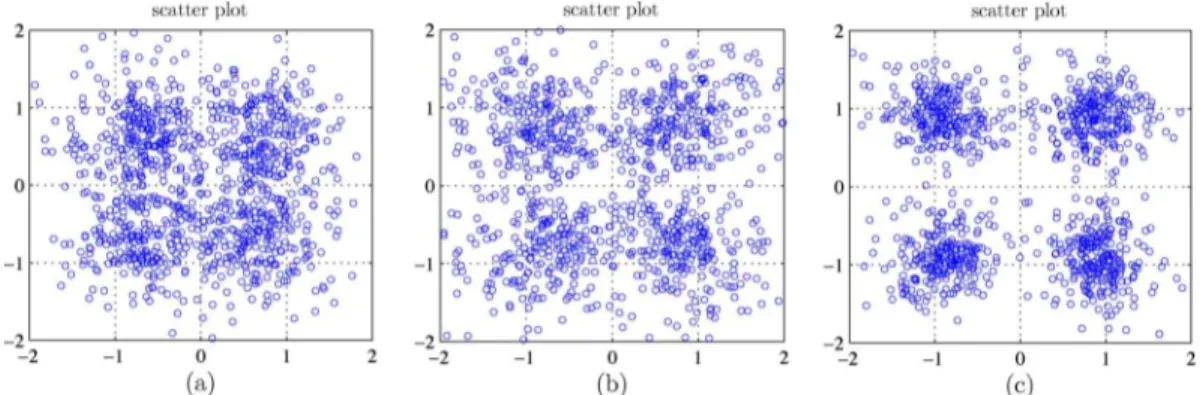
In Fig. 10, we show the channel estimates obtained from the frame synchronization preamble of a 2-km link for three consecutive nonadaptive QPSK-modulated OFDM frame trans-missions, labeled as , , and . As mentioned earlier, the av-erage time interval between two consecutive frame transmis-sions is (roughly) 20 s. Note the significant variations of the channel impulse response within a 1-min time interval. For the given consecutive OFDM frame transmissions, in Fig. 11, we provide the performance results for the receiver with four ele-ments. Note that poor performance is achieved for transmissions and , while a fair performance is obtained for transmission , corresponding to very high SNR observed at the receiver (see Fig. 10). If the target average BER for OFDM systems is set to 10 –10 , the nonadaptive scheme should use either more power, or reduce the overall throughput by employing the BPSK modulation alphabet which is preferable for the power limited systems.
Fig. 11. Scatter plots for three consecutive nonadaptive OFDM frame transmissions, each containing four OFDM blocks. The average time interval between two consecutive frame transmissions is (roughly) 20 s. The corresponding channel impulse response estimates are given in Fig. 10.
Fig. 12. Channel estimates from initial frame synchronization preamble for three consecutive adaptive OFDM frame transmissions. The average time in-terval between two consecutive frame transmissions is (roughly) 20 s.
Fig. 13. Scatter plot for the first adaptive OFDM frame transmission, each containing four OFDM blocks. The adaptive scheme 2 allocates only QPSK modulation alphabet to the data subcarriers.
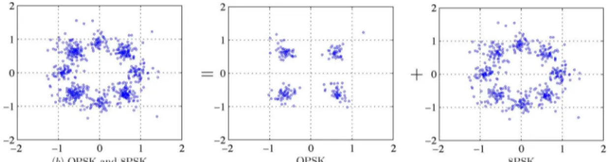
In Fig. 12, we illustrate channel estimates of a 2-km link for three consecutive adaptive OFDM frame transmissions, labeled as , , and . The available adaptive modulation alphabets are BPSK, QPSK, and 8PSK. As in the previous set of nonadaptive OFDM block transmissions, we note significant variations in the channel impulse response within a 1-min time interval. For the given consecutive OFDM frame transmissions, in Figs. 13–15,
we provide the performance results for the receiver with four elements. For the target average BER set to 10 –10 , we note that a good performance is achieved for all three transmis-sions ( , , and in Figs. 13–15, respectively), since scheme 2 successfully tracks the underlying channel variations. Due to large propagation delays and channel variations (the coherence time on the order of seconds) that impose severe limitations on channel prediction, the adaptive scheme tends to oscillate in performance around the target BER. In Figs. 16–18, we illus-trate the channel frequency response, the allocated power, and modulation levels across the data subcarriers, respectively. A high attenuation in the frequency region 30–35 kHz is mainly due to the cutoff frequency of the hydrophones, which is lo-cated around 30 kHz, resulting in a severe rolloff across the upper part of the operational bandwidth. We emphasize that this system limitation was not known a priori, and the whole opera-tional bandwidth (25–35 kHz) was used for OFDM transmis-sions. However, scheme 2 has successfully demonstrated the ability to adapt to the system limitations by allocating the power and modulation levels to the lower part of the frequency region, as illustrated in Figs. 17 and 18. Since the transition band of the hydrophone filter is not sharp, we can note an active tone lo-cated at 30.55 kHz; this artifact results from a sufficiently high channel gain present at the given frequency.
VI. CONCLUSION
In this paper, we explored design aspects for adaptive OFDM modulation over time-varying UWA channels. First, we investi-gated the possibility of predicting an UWA channel at least one travel time ahead. The key step in providing a stable reference for channel prediction is compensation of the motion-induced phase offset. MP algorithms are used to identify the significant path coefficients, which are then processed by a low-order adaptive RLS predictor to account for large prediction lags (long feedback delays). Second, assuming that the channel is predicted one travel time ahead with a given accuracy, approx-imate expressions for the BER of each subcarrier (or a cluster of adjacent subcarriers) are obtained. From these expressions, a set of thresholds is obtained that determine the modulation level and the power needed on each subcarrier to maximize the throughput while keeping the average BER at the target level. Third, spectrally efficient adaptive schemes (scheme 1 and scheme 2) are applied to allocate the modulation and
Fig. 14. Scatter plot for the second adaptive OFDM frame transmission, each containing four OFDM blocks. The adaptive scheme 2 allocates QPSK and 8PSK modulation alphabets to the data subcarriers.
Fig. 15. Scatter plot for the third adaptive OFDM frame transmission, each containing four OFDM blocks. The adaptive scheme 2 allocates QPSK and 8PSK modulation alphabets to the data subcarriers.
Fig. 16. A sample estimate of the channel frequency response for the OFDM system with subcarriers.
Fig. 17. A sample power allocation for data subcarriers based on scheme 2 and the channel response from Fig. 16.
the power across the OFDM subcarriers. Finally, assuming a limited feedback channel, two competitive strategies were analyzed: one that feeds back the quantized power and mod-ulation levels for each subcarrier/cluster, and another that feeds back the quantized estimate of the significant channel coefficients in the time domain. The second strategy is found to offer better performance, as it requires significantly fewer
Fig. 18. A sample constellation level allocation for data subcarriers based on scheme 2 and the channel response from Fig. 16.
feedback bits. Numerical and experimental results that are obtained with recorded channels and real-time at-sea experi-ments, respectively, show that the adaptive modulation scheme provides significant throughput improvements as compared to conventional, nonadaptive modulation at the same power and target BER. This work leads us to conclude that adaptive modulation methods may be viable for reliable, high-rate UWA communications. To our knowledge, this is the first paper that presents adaptive modulation results for UWA links with real-time at-sea experiments.
ACKNOWLEDGMENT
The authors would like to thank Dr. J. C. Preisig and K. R. Ball for their valuable comments, suggestions, and outstanding technical assistance during the KAM11 experiment.
REFERENCES
[1] M. Stojanovic, “Underwater acoustic communications: Design consid-erations on the physical layer,” in Proc. IEEE/IFIP 5th Annu. Conf. Wireless On Demand Netw. Syst. Services, Garmisch-Partenkirchen, Germany, January 2008, DOI: 10.1109/WONS.2008.4459349.
[2] Z. Liu, Y. Xin, and G. B. Giannakis, “Space-time-frequency coded OFDM over frequency-selective fading channels,” IEEE Trans. Signal Process., vol. 50, no. 10, pp. 2465–2476, Oct. 2002.
[3] P. Schniter, “Low-complexity equalization of OFDM in doubly selective channels,” IEEE Trans. Signal Process., vol. 52, no. 4, pp. 1002–1011, Apr. 2004.
[4] S. Ohno and G. B. Giannakis, “Capacity maximizing MMSE-op-timal pilots for wireless OFDM over frequency-selective block Rayleigh-fading channels,” IEEE Trans. Inf. Theory, vol. 50, no. 9, pp. 2138–2145, Sep. 2004.
[5] Y. Yao and G. B. Giannakis, “Rate-maximizing power allocation in OFDM based on partial channel knowledge,” IEEE Trans. Wireless Commun., vol. 4, no. 3, pp. 1073–1083, May 2005.
[6] L. Rugini and P. Banelli, “BER of OFDM systems impaired by carrier frequency offset in multipath fading channels,” IEEE Trans. Wireless Commun., vol. 4, no. 5, pp. 2279–2288, Sep. 2005.
[7] L. Rugini, P. Banelli, and G. Leus, “Low-complexity banded equalizers for OFDM systems in Doppler spread channels,” EURASIP J. Adv. Signal Process., 2006, DOI: 10.1155/ASP/2006/67404.
[8] I. Barhumi, G. Leus, and M. Moonen, “Equalization for OFDM over doubly-selective channels,” IEEE Trans. Signal Process., vol. 54, no. 4, pp. 1445–1458, Apr. 2006.
[9] Z. Tang, R. C. Cannizzaro, G. Leus, and P. Banelli, “Pilot-assisted time-varying channel estimation for OFDM systems,” IEEE Trans. Signal Process., vol. 55, no. 5, pp. 2226–2238, May 2007.
[10] Y. Emre, V. Kandasamy, T. M. Duman, P. Hursky, and S. Roy, “Multi-input multi-output OFDM for shallow-water UWA communi-cations,” in Proc. Acoustic, Paris, France, Jul. 2008 [Online]. Avail-able: http://webistem.com/acoustics2008/acoustics2008/cd1/data/arti-cles/000907.pdf
[11] K. Fang, L. Rugini, and G. Leus, “Low-complexity block turbo equalization for OFDM systems in time-varying channels,” IEEE Trans. Signal Process., vol. 56, no. 11, pp. 5555–5566, Nov. 2008.
[12] S. Ohno and K. A. D. Teo, “Viterbi-type inter-carrier interference equalization for OFDM over doubly selective channels,” IEICE Trans., vol. 92-A, no. 8, pp. 1905–1912, 2009.
[13] B. Li, S. Zhou, M. Stojanovic, L. Freitag, and P. Willet, “Multicarrier communications over underwater acoustic channels with nonuniform Doppler shifts,” IEEE J. Ocean. Eng., vol. 33, no. 2, pp. 198–209, Apr. 2008.
[14] B. Li, J. Huang, S. Zhou, K. Ball, M. Stojanovic, L. Freitag, and P. Willett, “MIMO-OFDM for high rate underwater acoustic commu-nications,” IEEE J. Ocean. Eng., vol. 34, no. 4, pp. 634–645, Oct. 2009.
[15] M. Stojanovic, “Low complexity OFDM detector for underwater acoustic channels,” in Proc. IEEE OCEANS Conf., Boston, MA, USA, Sep. 2006, DOI: 10.1109/OCEANS.2006.307057.
[16] M. Stojanovic, “OFDM for underwater acoustic communications: Adaptive synchronization and sparse channel estimation,” in Proc. Int. Conf. Acoust. Speech Signal Process., Apr. 2008, pp. 5288–5291.
[17] A. J. Goldsmith and S.-G. Chua, “Variable-rate variable-power MQAM for fading channels,” IEEE Trans. Commun., vol. 45, no. 10, pp. 1218–1230, Oct. 1997.
[18] D. L. Goeckel, “Adaptive coding for time-varying channels using out-dated fading estimates,” IEEE Trans. Commun., vol. 47, no. 6, pp. 844–855, Jun. 1999.
[19] T. Keller and L. Hanzo, “Adaptive multicarrier modulation: A convenient framework for time-frequency processing in wireless communications,” Proc. IEEE, vol. 88, no. 5, pp. 611–640, May 2000.
[20] P. Xia, S. Zhou, and G. B. Giannakis, “Adaptive MIMO-OFDM based on partial channel state information,” IEEE Trans. Signal Process., vol. 52, no. 1, pp. 202–213, Jan. 2004.
[21] B. Krongold, K. Ramchandran, and D. Jones, “Computationally effi-cient optimal power allocation algorithms for multicarrier communi-cation systems,” IEEE Trans. Commun., vol. 48, no. 1, pp. 23–27, Jan. 2000.
[22] S. Mani, T. M. Duman, and P. Hursky, “Adaptive coding/modulation for shallow-water UWA communications,” in Proc. Acoustic, Paris, France, Jul. 2008 [Online]. Available: http://webistem.com/acous-tics2008/acoustics2008/cd1/data/articles/000926.pdf
[23] C. Choudhuri and U. Mitra, “Capacity bounds and power allocation for underwater acoustic relay channels with ISI,” in Proc. 4th ACM Int. Workshop UnderWater Netw., Nov. 2009, DOI: 10.1145/1654130. 1654136.
[24] X. Huang and V. B. Lawrence, “Bandwidth-efficient bit and power loading for underwater acoustic OFDM communication systems with limited feedback,” in Proc. IEEE Conf. Veh. Technol., Spring, 2011, DOI: 10.1109/VETECS.2011.5956789.
[25] X. Huang, “Analysis and optimization of OFDM underwater acoustic communications,” Ph.D. dissertation, Stevens Inst. Technol., Hoboken, NJ, USA, Mar. 2011.
[26] A. Radosevic, T. M. Duman, J. G. Proakis, and M. Stojanovic, “Adap-tive OFDM for underwater acoustic channels with limited feedback,” in Proc. 45th Asilomar Conf. Signals Syst. Comput., Nov. 2011, pp. 975–980.
[27] A. Radosevic, T. M. Duman, J. G. Proakis, and M. Stojanovic, “Channel prediction for adaptive modulation in underwater acoustic communications,” in Proc. IEEE OCEANS Conf., Santander, Spain, Jun. 2011, DOI: 10.1109/Oceans-Spain.2011.6003438.
[28] D. G. Manolakis, V. K. Ingle, and S. M. Kogon, Statistical and Adap-tive Signal Processing. New York, NY, USA: McGraw-Hill, 2000, ch. 10.
[29] A. Radosevic, J. G. Proakis, and M. Stojanovic, “Statistical charac-terization and capacity of shallow water acoustic channels,” in Proc. IEEE OCEANS Conf., Bremen, Germany, May 2009, DOI: 10.1109/ OCEANSE.2009.5278349.
[30] W. Li and J. Preisig, “Estimation of rapidly time-varying sparse chan-nels,” IEEE J. Ocean. Eng., vol. 32, no. 4, pp. 927–939, Oct. 2007. [31] R. M. Corless, G. H. Gonnet, D. E. G. Hare, D. J. Jeffrey, and D. E.
Knuth, “On the Lambert W function,” Adv. Comput. Math., vol. 5, pp. 329–359, 1996.
[32] R. F. H. Fisher and J. B. Huber, “A new loading algorithm for discrete multitone transmission,” in Proc. GLOBECOM, London, U.K., Nov. 1996, pp. 724–728.
[33] J. Campello, “Practical bit loading for DMT,” in Proc. Int. Conf. Commun., Vancouver, BC, Canada, Jun. 1999, vol. 2, pp. 801–805. [34] S. Golomb, “Run-length encodings,” IEEE Trans. Inf. Theory, vol.
IT-24, no. 3, pp. 399–401, May 1966.
[35] J. Ziv and A. Lempel, “A universal algorithm for sequential data com-pression,” IEEE Trans. Inf. Theory, vol. IT-24, no. 3, pp. 337–343, May 1977.
[36] S. Mehrotra, “On the implementation of a primal-dual interior point method,” SIAM J. Optim., vol. 2, no. 4, pp. 575–601, 1992.
Andreja Radosevic (S’09) received the B.S. degree in electrical engineering from the University of Bel-grade, BelBel-grade, Serbia, in 2007 and the M.S. and Ph.D. degrees in electrical and computer engineering from the University of California San Diego, La Jolla, CA, USA, in 2009 and 2012, respectively.
Currently, he works at Qualcomm Technologies Inc., San Diego, CA, USA. His research inter-ests include channel capacity analysis, adaptive modulation, channel estimation, and orthogonal fre-quency-division multiplexing (OFDM) techniques, mainly in the context of underwater acoustic communications.
Rameez Ahmed received the B.Tech. degree in telecommunication engineering from the Vellore Institute of Technology, Vellore, Tamil Nadu, India, in 2008 and the M.S. degree in electrical and com-puter engineering from the Northeastern University, Boston, MA, USA, in 2010, where he is currently working toward the Ph.D. degree.
He is associated with the Communication and Digital Signal Processing (CDSP) Lab. He conducts research in underwater acoustic communication. His research interests include adaptive power control, orthogonal frequency-division multiplexing (OFDM) in the physical layer, fountain codes, ARQ techniques, and their applications to underwater acoustic communication.
Tolga M. Duman (S’97–M’98–SM’03–F’11) re-ceived the B.S. degree from Bilkent University, Bilkent, Ankara, Turkey, in 1993 and the M.S. and Ph.D. degrees from Northeastern University, Boston, MA, USA, in 1995 and 1998, respectively, all in electrical engineering.
He is a Professor at the Electrical and Electronics Engineering Department, Bilkent University, and is on leave from the School of Electrical, Computer and Energy Engineering, Arizona State University, Tempe, AZ, USA. Before joining Bilkent University in August 2012, he was with the Electrical Engineering Department, Arizona State University, first as an Assistant Professor (1998–2004), then as an Associate Professor (2004–2008), and starting August 2008 as a Professor. His publications include a book Coding for MIMO Communication Systems (New York, NY, USA: Wiley, 2007), over 50 journal papers, and over 100 conference papers. His current research interests are in systems, with particular focus on communication and signal processing, including wireless and mobile communications, coding/modulation, coding for wireless communications, data storage systems, and underwater acoustic communications.
Dr. Duman is a recipient of the National Science Foundation CAREER Award and the IEEE Third Millennium medal. He served as an editor for the IEEE TRANSACTIONS ONWIRELESSCOMMUNICATIONS(2003–2008), the IEEE TRANSACTIONS ONCOMMUNICATIONS (2007–2012), and the IEEE ONLINE
JOURNAL OF SURVEYS AND TUTORIALS (2002–2007). He is currently the coding and communication theory area editor for the IEEE TRANSACTIONS ONCOMMUNICATIONS (2011–present) and an editor for Elsevier’s Physical Communications Journal (2010–present).
John G. Proakis (S’58–M’62–F’84–LF’99) re-ceived the B.S.E.E. degree from the University of Cincinnati, Cincinnati, OH, USA, in 1959, the M.S.E.E. degree from the Massachusetts Institute of Technology (MIT), Cambridge, MA, USA, in 1961, and the Ph.D. degree from Harvard University, Cambridge, MA, USA, in 1967.
He is an Adjunct Professor at the University of California at San Diego, La Jolla, CA, USA, and a Professor Emeritus at Northeastern University, Boston, MA, USA. He was a faculty member at Northeastern University from 1969 through 1998 and held the following
aca-demic positions: Associate Professor of Electrical Engineering (1969–1976), Professor of Electrical Engineering (1976–1998), Associate Dean of the College of Engineering and Director of the Graduate School of Engineering (1982–1984), Interim Dean of the College of Engineering (1992– 1993), and Chairman of the Department of Electrical and Computer Engineering (1984–1997). Before joining Northeastern University, he worked at GTE Laboratories and the MIT Lincoln Laboratory. His professional experience and interests are in the general areas of digital communications and digital signal processing. He is the coauthor of the books Digital Communications (New York, NY, USA: McGraw-Hill, 2008, 5th ed.), Introduction to Digital Signal Processing (Upper Saddle River, NJ, USA: Prentice-Hall, 2007, 4th ed.), Dig-ital Signal Processing Laboratory (Englewood Cliffs, NJ, USA: Prentice-Hall, 1991), Advanced Digital Signal Processing (New York, NY, USA: Macmillan, 1992), Algorithms for Statistical Signal Processing (Upper Saddle River, NJ, USA: Prentice-Hall, 2002), Discrete-Time Processing of Speech Signals (New York, NY, USA: Macmillan, 1992, IEEE Press, 2000), Communication Systems Engineering (Upper Saddle River, NJ, USA: Prentice-Hall, 2002, 2nd ed.), Digital Signal Processing Using MATLAB V.4 (Boston, MA, USA: Brooks/Co-leThomson Learning, 2007, 2nd ed.), Contemporary Communication Systems Using MATLAB (Boston, MA, USA: Brooks/Cole-Thomson Learning, 2004, 2nd ed.), and Fundamentals of Communication Systems (Upper Saddle River, NJ, USA: Prentice-Hall, 2005).
Milica Stojanovic (SM’08–F’10) graduated from the University of Belgrade, Belgrade, Serbia, in 1988 and received the M.S. and Ph.D. degrees in electrical engineering from Northeastern University, Boston, MA, USA, in 1991 and 1993, respectively.
After a number of years with the Massachusetts In-stitute of Technology (MIT), Cambridge, MA, USA, where she was a Principal Scientist, she joined the faculty of Electrical and Computer Engineering De-partment, Northeastern University, in 2008. She is also a Guest Investigator at the Woods Hole Oceano-graphic Institution (WHOI), Woods Hole, MA, USA, and a Visiting Scientist at MIT. Her research interests include digital communications theory, statistical signal processing and wireless networks, and their applications to underwater acoustic communication systems.
Prof. Stojanovic is an Associate Editor for the IEEE JOURNAL OFOCEANIC