Introduction
In recent years all-ceramic materials have become increasingly important in restorative dentistry, as they offer superior esthetic and biocompatibility in comparison with metal-ceramic crowns. However, there is a risk of fracture especially in the posterior
region.
The clinical survival rate of all-ceramic restorations has become predictable. There have been several observational studies with a follow-up period in the literature1,2). The reported success rates vary
between 75% and 100%. Various factors can affect the long-term success of all-ceramic crowns such
J Korean Dent Sci. 2015;8(1):1-8 http://dx.doi.org/10.5856/JKDS.2015.8.1.1 ISSN 2005-4742
Influence of Crown Margin Design on the Stress
Distribution in Maxillary Canine Restored by
All-ceramic Crown: A Finite Element Analysis
Zafer Ozer
1, Cem Kurtoglu
2, Amirullah M. Mamedov
3, Ekmel Ozbay
31Mersin Vocational High School, Mersin University, Mersin, 2Faculty of Dentistry, Cukurova University, Adana, 3Nanotechnology Research Center (NANOTAM), Bilkent University, Ankara, Turkey
Purpose: To investigate the infl uence of crown margin design on the stress distribution and to localize critical sites in maxillary canine under functional loading by using three dimensional fi nite element analysis.
Materials and Methods: The bite force of 100 N, 150 N, and 200 N was applied with an angulation of 45° to the longitudinal axis of tooth. Six models were restored with IPS e.max (Ivoclar Vivadent, Schaan, Liechtenstein) with a different margin design. With lingual ledge and various thicknesses, three different core ceramics were designed in each model.
Result: In the core ceramic, the maximum tensile stresses were at the labiocervical region. In the veneering ceramic the maximum tensile stresses were at the area where the force was applied in all models.
Conclusion: Shoulder and chamfer margin types are acceptable for all-ceramic rehabilitations. A ledge on the core ceramic at cervical region may affect the strength of all-ceramic crowns.
Key Words: All ceramic crown; Crown margin design; Finite element analysis
Corresponding Author: Zafer Ozer
Mersin Vocational High School, Mersin University, Çiftlikköy Kampusu, Mersin 33343, Turkey TEL : +90-324-361-02-84, FAX : +90-324-482-22-21, E-mail : [email protected]
Received for publication 00 00, 2015; Returned after revision 00 00, 2015; Accepted for publication 00 00, 2015 Copyright © 2015 by Korean Academy of Dental Science
cc This is an open access article distributed under the terms of the Creative Commons Attribution Non-Commercial License (http://creativecommons.org/licenses/ by-nc/4.0) which permits unrestricted non-commercial use, distribution, and reproduction in any medium, provided the original work is properly cited.
as porcelain thickness, cementation type, margin type, marginal adaptation, tooth morphology, preparation design, functional and para-functional activities3-5).
All-ceramic restorations are more brittle than the metal-ceramic restorations. As a consequence, the preparation and cementation procedures are more critical for all-ceramic restorations5-7)
. The shape of the restoration and of the cement layer may influence the resistance of restoration to fracture. Adequate preparation guidelines such as margin design are therefore of importance and should be based on sound data, taking all possible parameters into account8). In manually produced restorations,
however, design weaknesses are diffi cult to detect. Finite element analysis (FEA) is a computer-based approach and a numerical solution method that is seeking an acceptable solution to the
various mechanical problems9-14)
. To determine the mechanical behavior of live tissues and organs against the forces, and to perform stress analysis are diffi cult, costly, and risky and can be technically impossible. Therefore, a model of stress analysis studies on the live material is necessary. Different force analysis should be conducted to see the area of the body that forces are concentrated and to detect the structure of the body.
In engineering applications, FEA allows optimi-zation of weight, materials, costs and entire designs to be constructed, before the design is manufactured15)
. The FEA method has several advantages over other methods; at first, solid objects having complex geometry can be modeled with realistic assumptions of a material, by which a realistic model can be created using software. Secondly, different models can be produced with any number of different materials. Thirdly, stress distribution and displacements can be obtained numerically. Based on these experiences it was hypothesized that FEA is a proper tool for the evaluation of suitable margin design for all-ceramic restorations. The purpose of this study was to evaluate the infl uence
of margin design on the stress distribution in all-ceramic restorations.
Materials and Methods
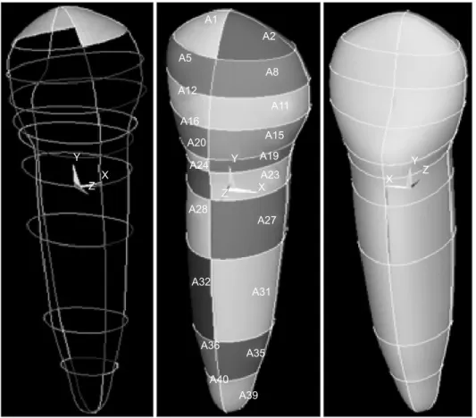
An anatomy-based maxillary canine was investi-gated utilizing three-dimensional finite element analyses (3D-FEA). For modeling, the dimensions of a typical maxillary canine crown were imported into computer aided design (CAD) software (ANSYS 11). Briefly, two-dimensional images of anatomical structure of teeth were traced, and these images were sent to CAD program. Coordinates from CAD made the outlines and the outlines were combined with segmented spline. Then it was digitized to create a 3D-FEM model (Fig. 1).
In this study, IPS e.max Press (Ivoclar Vivadent, Schaan, Liechtenstein) was used as core ceramics and IPS e.max Ceram (Ivoclar Vivadent) as veneering ceramics. The mechanical properties of these materials were obtained from the manufacturer’s website and the mechanical properties of the other materials were obtained from the literature (Table 1).
A tooth preparation was simulated by reducing the incisal edge by 2.0 mm, labial surface 1.3 mm, lingual surface 1 mm, axial surfaces 1.5 mm. Convergence of 7 degrees was created between the buccal and lingual walls as well as between the mesial and distal walls. Six different margin shapes were established as shoulder (model 1), rounded shoulder (model 2), shoulder with bevel (model 3), chamfer (model 4), deep chamfer (model 5), and knife edge (model 6). Thus six FE models were created to be used in this study. 100 N, 150 N, and 200 N load with a 45o oblique were applied and the
data were collected from FEA.
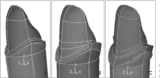
With different thickness of core ceramics and lingual ledge, three different core ceramic were designed as shown below and in Fig. 2. The element number and node numbers of created models are shown in Table 2. In determining the boundary
conditions, the bottom of jaw bone which the coated tooth created in finite element model was fi xed at the mesial and distal aspects. Loading and boundary conditions for different dental models are shown in Fig. 3 and 4.
The tensile stress in FEA was expressed as maximum principal stress (Pmax). The material fl exural strength as the basic mechanical properties of the material had the same character as the Pmax value and the stress pattern that was shown. If the value of Pmax observed in the analysis did
not exceed the tensile strength, the prediction of material integrity is preserved. Ceramics that are under forces that cause a tension of 40% flexural strength may be expected to function infinitely4).
Pmax values which are obtained in this study, therefore, are compared with 40% of flexural strength of ceramic systems endurance limit (EL).
Result
In terms of the stress distribution in the core ceramic, the maximum tensile stresses were found at the labiocervical region in all the models. In view of the stress distribution in the veneering ceramic, the maximum tensile stresses were at the area where the force was applied in all models.
When the 100 N, 150 N, and 200 N loads with a 45o
oblique were applied, the data collected from FEA with 6 FE models are shown in Tables 3~8. The strength of the materials used in this study, as shown in Table 1, was considered as an EL for Table 1. The properties of dental and dental coating materials
which are used
Material Elasticity modulus (MPa) Poisson ratio Flexural strength (MPa)
IPS e.max Ceram 65,000 0.24 90±10
IPS e.max Press 91,000 0.23 400±40
Dentin [20] 18,600 0.31 Varolink II [20] 8,300 0.24 Alveolar bone [20] 14,700 0.26 Y X Z Y X Z Z X Y A1 A2 A5 A8 A12 A11 A16 A15 A20 A19 A24 A23 A28 A27 A32 A31 A36 A35 A40
A39 Fig. 1. Three-dimensional
materials. Pmax values that had exceeded the material’s strength are shown in italic in Table 3~8. In the shoulder model, when 100 N and 150 N loads were applied, the safety limit was exceeded
in the core and veneering ceramics in all versions. When a 200 N load was applied, the safety limit was exceeded in veneering ceramics in all versions. When 100 N and 150 N loads were applied in the
A
B
C
X Y Z X Y Z Z YXFig. 2. (A) Core/0.5 version. (B) Core/0.5/ledge version. (C) Core/0.3 version.
Table 2. The element and node numbers of models used
Margin type Element number Node number
a version b version c version a version b version c version
Model 1 53869 55781 48262 74205 76766 67233 Model 2 45828 48779 51488 63939 68080 70744 Model 3 68443 70988 68843 93393 96823 93422 Model 4 71959 67026 61998 97218 91379 84873 Model 5 54194 53659 61206 75431 74555 83553 Model 6 40093 39581 42411 56444 55601 59198 X Y Z
Fig. 3. The force applied (arrow).
X Y Z
Table 3. Pmax values for shoulder model
Ceramic Version Shoulder model Flexural strength (MPa)
100 N 150 N 200 N 100% EL
IPS e.max Press a 49.971 74.956 99.942 400 160
IPS e.max Ceram a 24.316 36.473 48.631 90 36
IPS e.max Press b 44.02 66.031 88.035 400 160
IPS e.max Ceram b 23.697 35.546 47.395 90 36
IPS e.max Press c 46.302 69.452 88.035 400 160
IPS e.max Ceram c 17.403 26.104 47.395 90 36
EL: endurance limit.
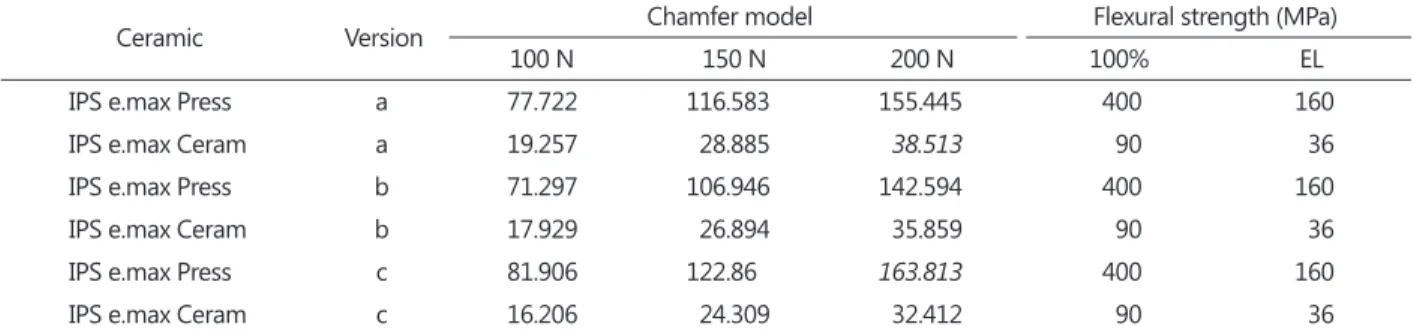
Table 4. Pmax values for chamfer model
Ceramic Version Chamfer model Flexural strength (MPa)
100 N 150 N 200 N 100% EL
IPS e.max Press a 77.722 116.583 155.445 400 160
IPS e.max Ceram a 19.257 28.885 38.513 90 36
IPS e.max Press b 71.297 106.946 142.594 400 160
IPS e.max Ceram b 17.929 26.894 35.859 90 36
IPS e.max Press c 81.906 122.86 163.813 400 160
IPS e.max Ceram c 16.206 24.309 32.412 90 36
EL: endurance limit.
Table 5. Pmax values for rounded shoulder model
Ceramic Version Rounded shoulder model Flexural strength (MPa)
100 N 150 N 200 N 100% EL
IPS e.max Press a 54.061 81.091 108.122 400 160
IPS e.max Ceram a 19.5 29.249 38.999 90 36
IPS e.max Press b 51.026 76.539 102.052 400 160
IPS e.max Ceram b 22.805 34.207 45.609 90 36
IPS e.max Press c 61.865 92.798 123.73 400 160
IPS e.max Ceram c 17.496 26.244 34.992 90 36
EL: endurance limit.
Table 6. Pmax values for deep chamfer model
Ceramic Version Deep chamfer model Flexural strength (MPa)
100 N 150 N 200 N 100% EL
IPS e.max Press a 53.806 80.71 107.613 400 160
IPS e.max Ceram a 22.956 34.434 45.912 90 36
IPS e.max Press b 60.388 90.582 120.776 400 160
IPS e.max Ceram b 22.75 34.125 45.5 90 36
IPS e.max Press c 64.594 96.891 129.186 400 160
IPS e.max Ceram c 17.611 26.416 35.222 90 36
chamfer model, the safety limits were exceeded in the core and veneering ceramics. When a 200 N load was applied, the veneering of core/0.5 version of ceramics, the core of core/0.3 version of ceramics exceeded the EL. In the core/0.5/ledge-version, the safety limit was not exceeded in response to all 100 N, 150 N, and 200 N loads.
In the rounded shoulder model in the core/0.3 version, the safety limit in the core and veneering ceramics was not exceeded under 100 N, 150N, and 200 N loads. When 100 N and 150 N loads were applied in the core/0.5 and core/0.5/ledge versions, the safety limit in the core and veneering ceramics were exceeded. When a 200 N load was applied in the core/0.5 and core/0.5/ledge versions, the safety limit in the core ceramics was not exceeded while veneering ceramics were exceeded.
In the deep chamfer model in the core/0.3 version, the safety limit in the core and veneering ceramics was exceeded by all 100 N, 150 N, and 200 N loads. When 100 N and 150 N loads were applied in the
deep chamfer model, the safety limit in the core and veneering ceramics was not exceeded. When a 200 N load was considered, the safety limit in the core ceramic was not exceeded but the veneering ceramics were exceeded.
When shoulder with the bevel model was tested under 100 N applied, in all versions core and veneering ceramics the safety limit was not exceeded. When a 150 N load was applied, the Pmax in thecore ceramics exceeded the safety limit while that of veneering ceramics did not. For 200 N, the Pmax in the core and veneering ceramics had exceeded the safety limit.
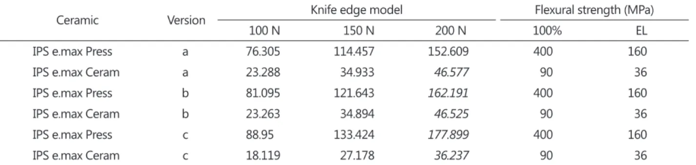
When 100 N and 150 N loads are applied in the knife edge model-in all versions, the Pmax in the core and veneering ceramics was within the safety limit. According to the 200 N, in the core/0.5/ledge and core/0.3 versions, the Pmax in the core and veneering ceramics exceeded the safety limit but not in the core/0.5 versions of both ceramics.
Table 7. Pmax values for shoulder with bevel model
Ceramic Version Shoulder with bevel model Flexural strength (MPa)
100 N 150 N 200 N 100% EL
IPS e.max Press a 134.355 201.532 269.34 400 160
IPS e.max Ceram a 22.295 33.443 44.582 90 36
IPS e.max Press b 122.555 183.832 245.109 400 160
IPS e.max Ceram b 21.493 32.24 42.987 90 36
IPS e.max Press c 127.962 191.943 255.924 400 160
IPS e.max Ceram c 18.613 27.919 37.226 90 36
EL: endurance limit.
Table 8. Pmax values for knife Edge model
Ceramic Version Knife edge model Flexural strength (MPa)
100 N 150 N 200 N 100% EL
IPS e.max Press a 76.305 114.457 152.609 400 160
IPS e.max Ceram a 23.288 34.933 46.577 90 36
IPS e.max Press b 81.095 121.643 162.191 400 160
IPS e.max Ceram b 23.263 34.894 46.525 90 36
IPS e.max Press c 88.95 133.424 177.899 400 160
IPS e.max Ceram c 18.119 27.178 36.237 90 36
Discussion
In the computer-designed and manufactured restorations, mechanical parameters are digitally available for stress analysis and failure prediction. Stress analysis using FEA appears to be the proper tool for such an evaluation. FEA was originally developed in the aircraft industry9)
. In dentistry, FEA has been used to determine stress distributions in teeth10)
. Many studies have been conducting the FEA of dental restorations8,11-13).
3D-FEA allows us to have a better biometrics of the restoration materials, biomechanically functional design of a restored tooth in order to optimize the restorative criteria and material choice.
Analysis results are compatible with the recom-mendations of the company. A mechanical test done by the authors in a previous study suggested the importance of thickness7)
. The analysis results were supported by the resultant mechanical test data. Among the restorations that used IPS e.max Ceram and IPS Press ceramics, in which the accumulation of stress that did not exceed the safety limit, 1mm wide rounded shoulder with rounded corners, core/0.3 version of rounded shoulder and deep chamfer, and the core/0.5/ledge version of chamfer margin type should be used. Bevel with a shoulder margin type is not recommended.
According to the manufacturer’s proposals, it was recommended that the thickness of the core ceramic should be 0.4 to 0.8 mm, and as a result of analysis the core ceramics needed to be thinner than the ceramic (0.3 mm) in all models, veneering ceramics had to be lower than accumulated stress. According to the end shape of the cervical region, there was no signifi cant difference in terms of stress intensity on the core ceramics in all models except on deep chamfer and knife edge model, the stress of core/0.5/ledge version was 5%~12% lower than the core/0.5 version and on the veneering ceramics, the stress was 2.5%~7% lower.
In the area in which stress accumulations are
intensive, the tensile stress can be seen as a starting point for failure along a long-term use. To avoid fracture, the veneer ceramics that have higher bending resistance can be used. Using only the core ceramic at the most intensive tensile forces area at the most intense may increase the resistance. Maximum tensile stresses in the core ceramic were located at the labiocervical region because of that type of crown margins and ledges were analyzed in this study. The effect of the margin type was investigated in some studies as in the metal-ceramic system firstly, then in ‘all-ceramic’ systems4,5). In
future studies, the effect of ledge height and number on the strength of core ceramics and in particular, the effect of lowering thickness of core-ceramic should be investigated.
From a material perspective, tooth preparation and crown thickness play a crucial role among some variables that affect the stress levels, as shown in a previous factorial analysis study3).
Conclusion
Within the limits of this study, following conclu-sions were made.
1. Shoulder and chamfer margin types are acceptable for all-ceramic crown rehabilitations. 2. A ledge on the core ceramic at cervical region may affect the strength of all-ceramic crowns.
Conflict of Interest
No potential conflict of interest relevant to this article was reported.
Acknowledgement
This work was supported by the projects DPT-HAMIT, DPT-FOTON, NATO-SET-193 and TUBITAK under Project Nos., 113E331, 109A015, 109E301. One of the authors (Ekmel Ozbay) also acknowledges partial support from the Turkish Academy of Sciences.
References
1. Pjetursson BE, Sailer I, Zwahlen M, Hämmerle CH. A systematic review of the survival and complication rates of all-ceramic and metal-ceramic reconstructions after an observation period of at least 3 years. Part I: single crowns. Clin Oral Implants Res. 2007; 18(Suppl 3): 73-85.
2. Beier US, Kapferer I, Dumfahrt H. Clinical long-term evaluation and failure characteristics of 1,335 all-ceramic restorations. Int J Prosthodont. 2012; 25: 70-8.
3. Rekow ED, Harsono M, Janal M, Thompson VP, Zhang G. Factorial analysis of variables infl uencing stress in all-ceramic crowns. Dent Mater. 2006; 22: 125-32.
4. Qasim T, Ford C, Bush MB, Hu X, Malament KA, Lawn BR. Margin failures in brittle dome structures: relevance to failure of dental crowns. J Biomed Mater Res B Appl Biomater. 2007; 80: 78-85.
5. Kokubo Y, Tsumita M, Kano T, Fukushima S. The infl uence of zirconia coping designs on the fracture load of all-ceramic molar crowns. Dent Mater J. 2011; 30: 281-5.
6. Kurtoglu C, Uysal H, Mamedov A. Influence of layer thickness on stress distribution in ceramic-cement-dentin multilayer systems. Dent Mater J. 2008; 27: 626-32.
7. Kurtoglu C, Demiroz SS, Mehmetov E, Uysal H. Stress distribution and damage mode of ceramic-dentin bilayer systems. Mod Phys Lett B. 2008; 22:
1317-27.
8. De Jager N, Pallav P, Feilzer AJ. The influence of design parameters on the FEA-determined stress distribution in CAD-CAM produced all-ceramic dental crowns. Dent Mater. 2005; 21: 242-51. 9. Turner MJ, Clough RW, Martin HC, Topp LJ.
Stiffness and deflection analysis of complex structures. J Aeronautical Sci. 1956; 23: 805-23. 10. Farah JW, Craig RG, Sikarskie DL. Photoelastic
and finite element stress analysis of a restored axisymmetric first molar. J Biomech. 1973; 6: 511-20.
11. Proos KA, Swain MV, Ironside J, Steven GP. Finite element analysis studies of an all-ceramic crown on a fi rst premolar. Int J Prosthodont. 2002; 15: 404-12.
12. Kamposiora P, Papavasilious G, Bayne SC, Felton DA. Finite element analysis estimates of cement microfracture under complete veneer crowns. J Prosthet Dent. 1994; 71: 435-41.
13. Hojjatie B, Anusavice KJ. Three-dimensional fi nite element analysis of glass-ceramic dental crowns. J Biomech. 1990; 23: 1157-66.
14. Ozer Z, Mamedov AM, Ozbay E. M`odeling and simulation of the ferroelectric based micro gyroscope: FEM analysis. Ferroelectrics. 2013; 446: 46-58.
15. Luo Y, Wang Z, Chen L, Wu J. Finite element analysis design of a split rotor bracket for a bulb turbine generator. Adv Mech Eng. 2013. doi: 10.1155/2013/428416.