Identifying magnetic response of split-ring resonators at microwave
frequencies
K. AYDIN
*1,2and E. OZBAY
1,2,31
Nanotechnology Research Centre, Bilkent University, Bilkent, 06-800 Ankara, Turkey
2Department of Physics, Bilkent University, Bilkent, 06-800 Ankara, Turkey
3
Department of Electrical and Electronics Engineering, Bilkent University, Bilkent, 06-800 Ankara, Turkey
In this study we provide experimental methods to identify the magnetic resonance of split ring resonators (SRR) at the micro-wave frequency regime. Transmission measurements were performed on both single SRR unit cell and periodic arrays of SRRs. The magnetic response of the SRR structure was demonstrated by comparing the transmission spectra of SRRs with closed ring resonators (CRR). Effects of the changes in the effective dielectric constant of the SRR medium on the band-gaps of SRR are investigated experimentally. SRRs not only exhibit a magnetic resonance band gap but also a band gap due to the electric resonance. Finally, we present the effect of electric coupling to the magnetic resonance of bianisotropic SRRs by uti-lizing SRRs with different orientations, and incident electromagnetic wave polarizations.
Keywords: split ring resonator, negative permeability, left-handed materials, metamaterials.
1. Introduction
The realization of media that exhibited the effective nega-tive index of refraction neffmade a great impact on the sci-entific community and received a considerable amount of interest recently. This in turn resulted in the discovery of various novel aspects of left-handed electromagnetism. In-spired by the proposal of Veselago in 1968 [1], an intuitive approach was taken to construct a composite medium, where the components simultaneously possess negative permittivityå < 0 and negative permeability ì < 0, over a certain frequency range [2]. In such a case, the wave vector of the propagating electromagnetic (EM) wave would be real and neff would be negative [3]. Periodically arranged
thin metallic wire structures are shown to exhibit the plasma frequency ùp in the microwave regime, below
which the material is opaque [4]. Since the dielectric permittivity becomes negative below ùp, thin wire arrays
are good candidates for the negativeå component of com-posite materials. Later, Pendry et al. proposed split-ring resonator (SRR) structures and demonstrated that such structures strongly respond to an incident magnetic field re-sulting in negative permeability near the magnetic reso-nance frequencyùm[5]. The experimental verification of
negative refraction is reported for such composite materials of SRRs and wires, supporting the existence of the negative refractive index neff < 0 medium [3,6,7]. These structures
are called left-handed metamaterials (LHM), attributing to the left-handed (LH) coordinate system formed by the EM wave components in the medium. In such media, the
elec-tric, magnetic, and wave vector components do not obey the right-hand rule [1].
Split ring resonators are responsible for the negative per-meability part of the negative refraction. The discovery of SRR structures by Pendry, enabled the possibility of obtain-ing left-handed materials. Since SRR structures are quite un-discovered and they are the essential components of LHMs for the time being, there are extensive studies in the litera-ture regarding the various aspects of SRR struclitera-tures. Trans-mission characteristics of periodic [8–11] and disordered SRRs [12] are studied experimentally in detail. Several works reported the numerical simulations of the transmis-sion properties [13–16], and the effective parameters [17,18] of SRRs. Electromagnetic resonance properties of SRRs are studied extensively in both theoretical and experimental manners[19–21]. Analytical models are reported to under-stand the origin of resonances and the effect of several pa-rameters on SRRs’ resonance behaviours [22–26]. The stud-ies on SRRs and metamaterials are mainly performed at the gigahertz (GHz) frequency regime because of their ease of fabrication, but recently there has been a tendency to in-crease the magnetic resonance frequencies of SRRs up to terahertz (THz) frequencies [27–30].
In this paper, we describe the methods for identifying the magnetic response of split-ring resonators at micro-wave frequencies. At the beginning, the split-ring resona-tors used in the experiments and experimental setups are introduced to the reader. In the results and discussion sec-tions, we discuss four different ways for verifying the mag-netic response of SRR structures. First, we measured the transmission through a single SRR unit cell and observed the resonant behaviour as a dip in the transmission
spec-DOI: 10.2478/s11772-006-0025-x
trum. Second, we made use of closed ring resonators to de-stroy the magnetic resonance. Third, we changed the effec-tive dielectric constant of the SRR medium and therefore affected the electric response rather than the magnetic re-sponse. The band-gap due to magnetic resonance was shown to be unaffected but the band gap due to electric res-onance changed. Lastly, we showed electric coupling to the magnetic resonance of SRRs. The transmission was mea-sured for the different polarization of EM waves and the different orientation of SRRs.
2. Spilt-ring resonator structures
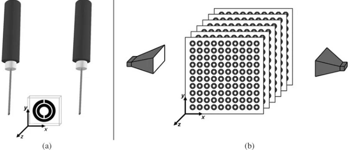
The SRR structure [3] proposed by Pendry et al. is com-monly used in LHM studies. This structure consists of two concentric rings separated by a gap, both of which have splits at the opposite sides [Fig. 1(a)]. LHMs are then fabri-cated as periodic structures of the alternating layers of SRRs and wires. In this study we focus on the magnetic re-sponse of SRR structures since they play an important role by providing the negative permeability component to the left-handed behaviour. Figure 1(a) shows a schematic drawing of a unit cell of SRR. The dark patterns belong to metal and the lighter patterns belong to the dielectric board. Metallic patterns are printed on FR4 dielectric printed cir-cuit boards (PCB). 30-mm thick copper is used for deposi-tion. The dielectric board has a thickness of 1.6 mm and di-electric constant ofå = 3.85. The width of the splits and the gap between the inner and outer rings are 0.2 mm, the metal width is 0.9 mm and the outer radius is 3.6 mm. The directions are provided in the figure. If the SRR structure is rotated along the z-axis by 90°, the SRR structure given in Fig. 1(b) is obtained.
SRR structures are subsequently arranged periodically to obtain negative permeability. The periodicity along the x and y directions is achieved by printing the 2D-arrays of SRR patterns on planar PCB boards. The periodicity in the
x and y directions are ax= ay= 8.8 mm. The periodicity in
the z direction is achieved by stacking a large number of such patterned planar substrates. The planar SRR boards
are stacked with a lattice constant of az= 6.5 mm along the z-axis. Notice that there is a 4.9 mm air region between the
neighbouring SRR boards.
3. Experimental setups
Two different experiments were performed in this study. One was the measurement of the transmission coefficients of a single SRR unit cell, and the other was that of a peri-odic array of SRRs and related structures. In order to deter-mine the magnetic resonance frequencyùm, we measured
the transmission through a single unit cell of SRR and CRR. Two monopole antennas were used to transmit and detect the EM waves through the single SRR unit cell. The monopole antenna was constructed by removing the shield around one end of a microwave coaxial cable. The exposed centre conductor, which also acted as the transmitter and receiver, was 3.8 mm long. This length is on the order of
ë/2, arranged to work at a frequency range covering the ùm
of the SRR structures. A single SRR was placed between the monopole antennas as shown in Fig. 2(a). The distance between the monopole and SRR unit cell is 6 mm. Mono-pole antennas were then connected to the HP-8510C net-work analyzer in order to measure the transmission coeffi-cients. First, we measured the transmission spectra in free space (i.e., without SRR unit cell), which is used as the cal-ibration data for the network analyzer. Then, a SRR unit cell was inserted between the monopole antennas, in which
Identifying magnetic response of split-ring resonators at microwave frequencies
Fig. 1. Single unit cell of split-ring resonators with a split-axis along the (A) y direction, (B) x direction.
ing the distance between the transmitter and receiver monopole antennas fixed.
For measuring the transmission through the periodic SRR arrays, standard high-gain microwave horn antennas were connected to the HP 8510C network analyzer. One of the horn antennas transmitted the electromagnetic (EM) wave and the other one detected the transmitted EM wave. The transmission spectrum in free space was measured and set as the calibration data for the network analyzer. Then, the structure was inserted between the horn antennas, in which the transmission measurements were performed. The distance between the horn antennas was maintained at 35 cm to ensure that the near fields would not have consider-able effects on the transmission. Both transmission mea-surements were performed in free space (air) rather than a waveguide environment.
4. Results and discussions
Before we commence to report these methods, we need to mention that the SRR structures that were used in this study were previously reported to exhibit left-handed be-haviour when combined together with a proper thin wire medium [6,9]. The LHM structure composed of these SRRs also have a negative index of refraction [6,7]. How-ever, in this study we aimed to show the magnetic response of SRRs without making use of thin wire structures, but rather focusing only on the SRR structures. The magnetic response of SRRs also could be verified by using theoreti-cal methods such as retrieval procedures and determining the field patterns inside the SRR structure. This study, however, brings attention to the experimental methods. This section is divided into 4 subsections; in each subsec-tion we show a different method to identify the magnetic response of SRR structures.
4.1. Magnetic response of SRR unit cell
The SRR structure is strongly resonant around the mag-netic plasma frequency ùm [5], which is induced by the
currents and split, which imitates magnetic poles. This res-onant behaviour is due to capacitive elements such as gaps and splits, and in turn results in very high positive and neg-ative values of permeability close toùm. If a single SRR
unit cell is excited with an EM wave with the appropriate polarization, the SRRs give a strong response to the mag-netic component of the incident field due to the magmag-netic resonance. This resonant behaviour of SRRs can be experi-mentally observed by measuring the transmission through SRRs. Subsequently, a dip in the transmission spectrum of the SRR structure can be attributed to the resonant nature of SRRs [20].
We measured the transmission through SRRs for two different orientations as seen in Fig. 1. Imagine a line that connects two splits and for the convention we name this imaginary line as split-axis. For the SRR (A) structure a
structure it is parallel to the x-axis. The incident EM wave propagates along the x direction, with an electric field E and magnetic field H along the y and z directions, respec-tively. For such a polarization, the magnetic field is perpen-dicular to the SRR plane (located at x-y plane) and there-fore excites the magnetic resonance of SRRs for both ori-entations.
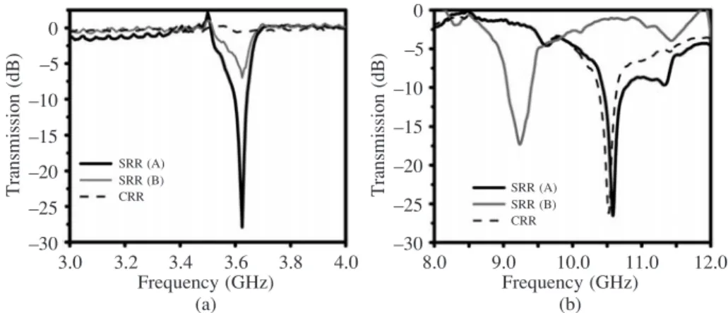
Figure 3(a) shows the measured transmission spectra for single SRR (A) and SRR (B) structures. Both of the SRR structures have dips at the transmission spectra at a frequency of 3.82 GHz. However, the dip values are quite different for these SRRs. The SRR (A) structure has a dip value of –28 dB, on the other hand, the dip value for the SRR (B) is –7 dB. Therefore, the orientation of the SRR structure with respect to an electric field may affect the strength of the resonance. This reduction in dip value for the SRR (B) structure can be explained by an electric cou-pling to the magnetic resonance, which will be explained in sec. 4.4.
Notice that the wavelength is 7.86 cm, whereas the di-ameter of the SRR structure is 7.2 mm. Therefore, by em-ploying the aforementioned SRR structure with sizes corre-sponding to the 1/11thof free space wavelength, magnetic
resonance can be obtained. The wavelength in the material (4.0 cm) is even approximately 1/6thof structure size. The
reason why SRR received a great amount of interest is not only because of being a source for negative permeability, but also for achieving resonance with subwavelength fea-tures. Therefore, an effective medium theory becomes ap-plicable for SRR media, and LHMs.
4.2. Closed ring resonator structure for verifying
magnetic resonance
The splits in the SRR structure play a key role for obtaining magnetic resonance. Removing the splits will prevent cur-rent from flowing between the inner and outer rings [21]. Since there is not any more current flowing between the concentric rings, the magnetic resonance will be destroyed [9]. We have employed a structure where the splits at the rings of the SRR are removed. The resulting structure is then two concentric rings separated by a gap. As a conven-tion we call this structure a closed ring resonator (CRR). The measured transmission spectra of a single CRR unit cell are provided in Fig. 3(a) with dashed lines. Throughout the frequencies of interest, the incident EM wave is com-pletely transmitted. This clearly proves that the resonance observed in sec. 4.1 is of magnetic origin.
The SRR structure does not only exhibit magnetic reso-nance induced by the splits at the rings. Electric resoreso-nance is also present via the dipole-like charge distribution along the incident electric field. Figure 3(b) shows the frequency response of single SRR at higher frequencies between 8–12 GHz. Evidently, we have observed sharp dip for SRR (A) and CRR structure at the same frequency, 10.6 GHz.
Closing the split did not destroy the electrical resonance for SRR (A) structure. Interestingly, the electrical resonance frequency for SRR (B) structure is observed at a lower fre-quency, 9.2 GHz. One should expect the electrical reso-nance to be at same frequencies for all structures, however, the behaviour is different for SRR (B) structure. We attrib-ute this behaviour to the orientation of the splits with re-spect to the electric field. In SRR (A) structure, the electric field does not see the splits, however, in SRR (B) case the electric field does indeed see the splits. This results a downward shift in the electrical resonance of the SRR.
A band gap in the transmission spectrum of a periodic SRR medium may be due to the negativee or negative ì, or solely due to the periodicity. The ambiguity can be lifted by using the CRR structure. This will destroy the magnetic resonance but retain the electric resonance. A frequency gap that is present in the transmission spectrum of SRR medium but not in the CRR medium will correspond to
ì < 0. We have measured transmission through the periodic
arrays of SRR and CRR structures. The number of unit cells along the x, y, and z directions are Nx= 10, Ny= 20,
and Nz= 25. The incident EM wave propagates along the x
direction, while E is along the y direction, and H is along the z direction [see Fig. 2(b) for the directions]. Figure 4 shows the measured transmission spectra of periodic SRRs (solid line) and CRRs (dashed line) between 3–13 GHz. The results provided in Fig. 4 belong to the SRR (A) con-figuration. The first band gap in the transmission spectrum of the SRR medium between 3.55–4.05 GHz is not present in that of the CRR medium. However, the second band gap (8.3–12.0 GHz) is present for both the SRR and CRR ar-rays. Therefore, the first band gap is due to the magnetic resonance induced by the splits and thus permeability be-comes negative throughout the band gap. This measure-ment clearly shows that the stop bands of an SRR medium cannot be automatically assumed as a result of “negativeì” behaviour. Some of the observed gaps (such as a second band gap in this measurement) in the transmission spectra could also originate from the electrical response of the SRRs or from Bragg gaps due to periodicity. There is an-other band gap above 13 GHz (data not shown here), where
the structure size and lattice constant becomes comparable to the wavelength and thus periodic effects becomes domi-nant in determining the band gap.
4.3. Changing effective dielectric constant of SRR
medium
In the previous section we investigated the transmission characteristics of SRR by removing the splits of the rings. The origins behind the formation of the first and second band gap of SRRs were shown to be different. The first band gap is due to magnetic resonance, whereas the second band gap is the result of electric resonance. SRRs, in addi-tion to their resonant magnetic response at wm, exhibit a
second resonant response at the higher frequencywowhich
has an electrical character [18]. The behaviour is similar to that of a periodic cut-wire medium that exhibits a stop band with a well-defined lower edge due to its discontinuous wire geometry [8]. In this section we investigate this elec-tric resonance by changing the effective dielecelec-tric constant of the SRR medium.
We first increased the lattice spacing between the SRR planes, i.e., along the z-direction. We chose the structure in sec 4.2 as the reference structure which has a lattice con-stant of az = 6.5 mm. We increased the lattice spacing to Identifying magnetic response of split-ring resonators at microwave frequencies
Fig. 3. Measured transmission spectra of single unit cell of SRR (A), SRR (B) and CRR structures (a) between 3–4 GHz and (b) between 8–12 GHz.
Fig. 4. Measured transmission spectra of periodic arrays of SRR (solid line) and CRR (dashed-dotted line) structures.
SRR array is decreased since the unit cell is filled with more air compared to the reference SRR array. The mea-surements in this section are performed by using arrays composed of SRR(A) configuration. The measured trans-mission spectra for SRRs with different lattice spacings are plotted in Fig. 5(a). The first band gap is present for both cases, although the lattice constant is increased approxi-mately on the order of 2. On the other hand, the second band gap is changed with an increase in the lattice constant. The second band gap for SRRs with az= 6.5 mm (solid) is
between 8.3–12.0 GHz, whereas for SRRs with az= 11.0
mm (dashed) the second band gap between 8.6–11.3 GHz becomes narrower.
As pointed out in sec. 2, the SRRs are deposited on a dielectric board of thickness w = 1.6 mm. We have in-creased the thickness of the dielectric board by a factor of 2, and obtained SRR planes with w = 3.2 mm thickness. Lattice spacing is kept at az= 6.5 mm, therefore almost half
of the unit cell is now filled with a dielectric board. The comparison in the transmission spectra of SRRs with dif-ferent thicknesses of dielectric board are provided in Fig. 5(b). The first band gap remains unaffected, but there is a downward shift in the second band gap for SRRs with w = 3.2 mm thick dielectric (dashed). The new frequency range of the band gap is 7.8–11.1 GHz.
As discussed in sec. 4.1, single SRR is resonant at a very narrow frequency range. Arranging SRR structures periodically in all directions increases the coupling be-tween the SRRs, therefore, a wider band gap in the trans-mission spectrum is observed compared to that of single SRR. It is worth mentioning that changing the effective di-electric constant of the medium does not affect the mag-netic resonance band gap. The coupling of SRRs mainly occurs in the SRR plane. The effect of inter-plane coupling between the neighbouring SRR planes is not as dominant as intra-plane coupling.
4.4. Observation of electric coupling to magnetic
resonance of SRRs
The first band gap in the transmission spectra of the SRR structure as discussed in sec. 4.2 was mentioned to be a fact of magnetic resonance excitation by magnetic field. How-ever, it has been recently argued that for the specific orien-tation of SRR and polarization of an incident EM wave, it is possible to obtain a resonance due to electric field excita-tion [10,21].
In this section we show the cross-polarization effect of the current SRR design. We have performed transmission measurements on periodic arrays of SRR structures. Four different measurements are performed for combinations of different orientations [(A) and (B) in Fig. 1] and different polarizations (parallel and perpendicular polarization). No-tice that magnetic permeability is only achievable via par-allel polarization, where the wave vector is parpar-allel to the
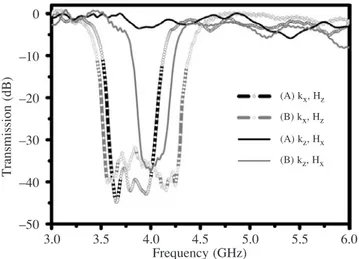
SRR plane and the H-field is along the z-axis. A magnetic field perpendicular to the SRR induces current loops at the resonance. In sec. 4.1, we investigated the resonance due to the single unit cell of SRR (A) and (B) structures for paral-lel polarization. Figure 6 gives the response of a periodic array of such structures to the incident plane wave. Both structures have a band gap at the transmission spectra. For the SRR (B) structure, a wider band gap is observed be-tween 3.5–4.3 GHz. The band gap is narrower for the SRR (A) array with a range of 3.55–4.05 GHz. Since the wave vector is parallel to the SRR plane, the type of polarization is called parallel polarization for the convention.
For the perpendicular polarization case, the wave vector is orthogonal to the SRR plane (along z-axis), the E-field is along the y-axis and the H-field is along the x-axis. In this case, the magnetic field cannot excite a magnetic resonance since it is now parallel to the SRR plane. However, an elec-tric field can induce current loops for SRR (B) orientation. We measured the transmission through a SRR periodic ar-ray with the number of unit cells along the x, y, and z direc-tions at Nx= 20, Ny= 20, and Nz=10. A band gap between
3.86–4.20 GHz was observed in the transmission spectra of the SRR (B) structure for perpendicular polarization, whereas the incident waves were completely transmitted
Fig. 5. Measured transmission spectra of (a) periodic arrays of SRR structures with lattice spacing along z directions az = 6.5 mm
(solid) and az= 11.0 mm (dashed), and (b) periodic arrays of SRR
structures with PCB board thickness wPCB= 1.6 mm (solid) and
for SRR (A) structure. In this case the SRR’s mirror sym-metry is no longer present with respect to the electric field direction; because of the orientation of the splits [10]. This structure has cross-polarization effects rendering the mag-netic resonance for a certain orientation [21]. This is a fact of bianisotropic behaviour of Pendry’s original SRR de-sign. There were several attempts in literature to obtain nonbianisotropic SRR designs [22,23,31].
This electric coupling to the magnetic resonance effect is a useful tool for obtaining magnetic responses of bianiso-tropic SRRs at higher frequencies such as THz frequencies [27–29]. For parallel polarization one needs to stack lots of SRR samples and therefore much more time is required to fabricate those structures. Additionally, the misalignment will become an important issue at those frequencies [12]. However, 5 to 10 samples are sufficient to observe the aforementioned cross-polarization effect by making use of the perpendicular polarization.
5. Conclusions
To conclude, we performed transmission measurements on split-ring resonator structures. The transmission through a single unit cell, and the periodic arrays of SRRs were mea-sured and interpreted. A single unit cell of SRR was shown to be strongly resonant at a certain magnetic resonance fre-quency with a dip value of –28 dB at the transmission spec-tra. The closed ring resonator structure is proposed to ver-ify the magnetic response of the SRRs. The band gap dis-appeared for the transmission spectrum of CRR, indicating the magnetic response, thus the negative permeability of SRRs. The magnetic resonance band gap of SRRs were shown to be unaffected by the changes in the effective di-electric constant of the SRR medium. The di-electric reso-nance band gap, however, is affected considerably with the
change in the dielectric constant of the medium. Finally, we observed the cross-polarization effect of SRR struc-tures. For certain orientation of the bianisotropic SRRs and the perpendicular polarization to the SRR plane, the elec-tric field couples to the magnetic resonance and renders the negative permeability together with the negative permitti-vity.
Acknowledgements
This work is supported by the European Union under the projects DALHM, NOE-METAMORPHOSE, EU-NOE-PHOREMOST, and TUBITAK under Project No. 104E090. One of the authors (Ekmel Ozbay) also acknowl-edges partial support from the Turkish Academy of Sci-ences.
References
1. V.G. Veselago, “The electrodynamics of substances with si-multaneously negative values of permittivity and permeabil-ity”, Sov. Phys. Usp. 10, 509–514 (1968).
2. D.R. Smith, W.J. Padilla, D.C. Vier, S.C. Nemat-Nasser, and S. Schultz, “Composite medium with simultaneously negative permeability and permittivity”, Phys. Rev. Lett. 84, 4184–4187 (2000).
3. R.A. Shelby, D.R. Smith, and S. Schultz, “Experimental verification of a negative index of refraction”, Science 292, 77–79 (2001).
4. J.B. Pendry, A.J. Holden, W.J. Stewart, and I. Youngs, “Ex-tremely low frequency plasmons in metallic mesostructu-res”, Phys. Rev. Lett. 76, 4773–4776 (1996).
5. J.B. Pendry, A.J. Holden, D.J. Robbins, and W.J. Stewart, “Magnetism from conductors and enhanced nonlinear phe-nomena”, IEEE Trans. Microwave Theory Tech. 47, 2075–2084 (1999).
6. K. Aydin, K. Guven, C.M. Soukoulis, and E. Ozbay, “Ob-servation of negative refraction and negative phase velocity in left-handed metamaterials”, Appl. Phys. Lett. 86, 124102 (2005).
7. K. Aydin and E. Ozbay, “Negative refraction through an impedance-matched left-handed metamaterial slab”, J. Opt.
Soc. Am. B23, 415–418 (2006).
8. E. Ozbay, K. Aydin, E. Cubukcu, and M. Bayindir, “Trans-mission and reflection properties of composite double nega-tive metamaterials in free space”, IEEE Trans. Antennas
Propag. 51, 2592–2595 (2003).
9. K. Aydin, K. Guven, M. Kafesaki, L. Zhang, C.M. Soukoulis, and E. Ozbay, “Experimental observation of true left-handed transmission peak in metamaterials”, Opt. Lett.
29, 2623–2625 (2004).
10. N. Katsarakis, T. Koschny, M. Kafesaki, E.N. Economou, and C.M. Soukoulis, “Electric coupling to the magnetic res-onance of split ring resonators”, Appl. Phys. Lett. 84, 2943–2945 (2004).
11. Y. Qi, B. Hou, and W. Wen, “Band gaps from ring resona-tors and structural periodicity”, J. Phys. D: Appl. Phys. 38, 590–595 (2005).
12. K. Aydin, K. Guven, N. Katsarakis, C.M. Soukoulis, and E. Ozbay, “Effect of disorder on magnetic resonance band gap
Identifying magnetic response of split-ring resonators at microwave frequencies
Fig. 6. Measured transmission spectra of SRR (A) structure with incident electromagnetic wave propagating along the x direction with a magnetic field along the z-direction (bold black line with circles), SRR (B) structure with kxand Hz(bold gray line with
circles), SRR (A) structure with kzand Hx(black solid line), and
(2004).
13. P. Markos, and C.M. Soukoulis, “Numerical studies of left-handed materials and arrays of split ring resonators”,
Phys. Rev. E65, 036622 (2002).
14. R.W. Ziolkowski, “Design, fabrication, and testing of dou-ble negative metamaterials”, IEEE Trans. Antennas Propag.
51, 1516–1529 (2003).
15. M. Kafesaki, Th. Koschny, R.S. Penciu, T.F. Gundogdu, E.N. Economou, and C.M. Soukoulis, “Left-handed meta-materials: detailed numerical studies of the transmission properties”, J. Opt. A: Pure Appl. Opt. 7, S12–S22 (2005). 16. E.A. Semouchkina, G.B. Semouchkin, M. Lanagan, and
C.A. Randall, “FDTD study of resonance processes in meta-materials”, IEEE Trans. Microwave Theory Tech. 53, 1477–1487 (2005).
17. T. Koschny, P. Markos, D.R. Smith, and C.M. Soukoulis, “Resonant and antiresonant frequency dependence of the ef-fective parameters of metamaterials”, Phys. Rev. E68, 065602(R) (2003).
18. T. Koschny, M. Kafesaki, E.N. Economou, and C.M. Soukoulis, “Effective medium theory of left-handed materi-als”, Phys. Rev. Lett. 93, 107402 (2004).
19. P. Gay-Balmaz, and O.J.F. Martin, “Electromagnetic reso-nances in individual and coupled split-ring resonators”, J.
Appl. Phys. 92, 2929–2936 (2002).
20. K. Aydin, I. Bulu, K. Guven, M. Kafesaki, C.M. Soukoulis, and E. Ozbay, “Investigation of magnetic resonances for different split-ring resonator parameters and designs”, New
J. Phys. 7, 168 (2005).
21. J. García–García, F. Martín, J.D. Baena, R. Marques, and L. Jelinek, “On the resonances and polarizabilities of split ring resonators”, J. Appl. Phys. 98, 033103 (2005).
22. R. Marques, F. Mesa, J. Martel, and F. Medina, “Compara-tive analysis of edge- and broadside-coupled split ring
reso-IEEE Trans. Antennas Propag. 51, 2572–2581 (2003).
23. R. Marques, F. Medina, and R. Rafii-El-Idrissi, “Role of bianisotropy in negative permeability and left-handed meta-materials”, Phys. Rev. B65, 144440 (2002).
24. B. Sauviac, C.R. Simovski, and S.A. Tretyakov, “Double split-ring resonators: Analytical modelling and numerical simulations”, Electromagnetics 24, 317–338 (2004). 25. M. Shamonin, E. Shamonina, V. Kalinin, and L. Solymar,
“Properties of a metamaterial element: Analytical solutions and numerical simulations for a singly split double ring”, J.
Appl. Phys. 95, 3778–3784 (2004).
26. J.D. Baena, J. Bonache, F. Martín, R.M. Sillero, F. Falcone, T. Lopetegi, M.A.G. Laso, J. García–García, I. Gil, M.F. Portillo, and M. Sorolla, “Equivalent-circuit models for split-ring resonators and complementary split-ring resona-tors coupled to planar transmission lines”, IEEE Trans.
Mi-crowave Theory Tech. 53, 1451–1461 (2005).
27. T.J. Yen, W.J. Padilla, N. Fang, D.C. Vier, D.R. Smith, J.B. Pendry, D.N. Basov, and X. Zhang, “Terahertz magnetic re-sponse from artificial materials”, Science 303, 1494–1496 (2004).
28. S. Linden, C. Enkrich, M. Wegener, J. Zhou, T. Koschny, and C.M. Soukoulis, “Magnetic response of metamaterials at 100 terahertz”, Science 306, 1351–1353 (2004). 29. N. Katsarakis, G. Konstantinidis, A. Kostopoulos, R.S.
Penciu, T.F. Gundogdu, M. Kafesaki, E.N. Economou, Th. Koschny, and C.M. Soukoulis, “Magnetic response of split-ring resonators in the far-infrared frequency regime”, Opt.
Lett. 30, 1348–1350 (2005).
30. J. Zhou, Th. Koschny, M. Kafesaki, E.N. Economou, J.B. Pendry, and C.M. Soukoulis, “Saturation of the magnetic response of split-ring resonators at optical frequencies”,
Phys. Rev. Lett. 95, 223902 (2005).
31. I. Bulu, H. Caglayan, and E. Ozbay, “Experimental demon-stration of labyrinth-based left-handed metamaterials”, Opt.