CONSTRUCTIONAL DESIGN OF CURTAIN WALL FAÇADE
INSPIRED BY “HYDRAULICS” SCIENCE
Asem Sharbaf
Department of Architecture, Iran university of Scince & Technology [email protected]
Mitra Sharbaf
Department of Architecture, Islamic Azad University of Tabriz [email protected]
Ghasem Sharbaf
Department of civil engineering, University of Hormozgan [email protected]
ABSTRACT
In recent years, the facade construction has been changed a lot. The use of curtain wall facades is the best solution to Supply the demands of the building engineering group. The curtain wall Facade has a capability to supply the expectations of the facade. There are large spectrums of construction system for curtain wall Facades that mainly concerned with the quality of their functions. Besides, we are able to mention the common points that can be seen among the facades such as: integration, lightness and particularly their transparency. The cable net façade is a new generation of Curtain wall Façade, having been previously used as a cable net structure to cover vast areas. According to the overall structure of the cable net Facade, there is a possibility that can be increased integration of façade. On the other, by increasing the façade’s area, other destructive factors such as vibration and large displacement are involved in the facade design. Many solutions have been proposed to eliminate these factors, mainly affecting the transparency of the facade. In this article, we are trying to offer a mention called ''hydraulics science'' as an appropriate solution. ''Damper'' is just one of their applications in the construction industry that is mainly used in the issue related to earthquake. Therefore, by using the structure and function of ''damper'' system as well as taking inspiration from industrial use of it, a new mention has been presented that can reduce the effects of vibration on the façade and correspondingly utilize its output energy.
Keywords: Curtain wall façade , Constructional design , hydraulics science , Damper.
PERDE DUVAR CEPHENIN YAPISAL TASARIMI:
"HİDROLİK BİLİM”
Son yıllarda, cephe inşaatı çok değişmiştir. Perde duvar cephesi kullanımı inşaat mühendisliği grubunun taleplerini tedarik için en iyi çözümdür. Entegrasyon, hafiflik ve özellikle de şeffaflık öneml ietkenlerdir. Ayrıca, cepheler arasında görülebilir ortak noktalardan söz edebiliyoruz. Kablo net cephe daha önce geniş alanları kapsayacak şekilde net bir yapı olarak kullanıma sahiptir. Kablo net cephenin, dış cephenin genel yapısına göre, cephe entegrasyonu arttırılabilme olasılığı vardır. Öte yandan, ön cephenin alanını arttırarak, bu tür titreşim ve büyük yer değiştirmesi gibi diğer yıkıcı unsurlar cephe tasarımına katılmaktadır. Birçok çözümler ağırlıklı cephe şeffaflığını etkileyen, bu faktörleri ortadan kaldırmak için ileri sürülmüştür. Bu yazıda, uygun bir çözüm olarak 'hidrolik bilimi' 'olarak adlandırılan bir araştırma ortaya konmaktadır. ''Damper'' sadece esas depreme ilişkin konuda kullanılan inşaat sektöründe kendi uygulamalarından biridir. Bu nedenle, 'amortisör' sistem yapısını ve fonksiyonunu kullanarak yanı sıra bunun endüstriyel kullanım ilham alarak, yeni bir söz cephesinde titreşim etkilerini azaltmak ve buna çıkış enerjisini kullanabileceği anlamına sunulmuştur.
Anahtar Kelimeler: Perde duvar cephe, Yapısal tasarım, hidrolik bilimi, Amortisör. INTRODUCTION
When "le corbusier" presented the idea "a house is a machine for living", it brought much criticism. So that many architects now think that he was a biased architect concerning with the industrial changes in his own time. But now, his idea considering it without any sentimental biases, could be inferred to be a part of the architecture foresight that has taken most architects' attention nowadays. In fact, le corbusier's idea says that it can provide user's convenience and welfare at home inspiring from thoughtful designings in different industries. This issue can be easily found in japanese flexible houses. Nowadays, the effects of industry in construction is undeniable. But according to the development of industry process, taking patterns and models from different industries can be an applicable solution for the architects. A specialized encounter with any structural components is appropriate for progression in construction itself. One of the important and effective bases in building is its facade, so that it is the first step to make a connection with its addressee and surroundings. Accordingly, it is considered as one of the vital bases that has many effects on interactions among addressee, surroundings and building. But according to the development in the building science, it is expected that the building facade be up to date with industry and keeps its esthetic values. If we glance at the building facade in a specialized manner, we can understand that the traditional attitude to the facade is not able to supply the architects' needs anymore. So the development of "curtain wall facade" tries to wash out the past limitations in construction process. The facade of the modern buildings including vast complexes, skyscrapers etc. needs to have capabilities more than its simple traditional kind. These facades must be able to protect privacy, provide safety and above all, to keep and save the energy. The curtain wall facade provides an independent structure from the main block of the building that helps the architects to design a facade by using modern technology and architectural creativity. These facades meets the essential demands in this area.
The curtain wall is one of the best examples of modern architecture’s quest for the incredible lightness of buildings.
Therefore, in order to fulfill the objects of this essay, at first, the kind of structure used in the facade has been discussed according to the features of curtain wall facade. "Cable net facade" is a new generation of the curtain wall facade which has increased the engineering capacitance in maintaining the constancy and the structure of facade, and it has taken the engineers' attention according to its lightness and having the power to enhance the designers' maneuver capacity. The cable net facade can cover the facade with a minimum amount of facade structural bases, so that the intruding elements to the transparency of the facade have been used in a very low degree. But according to the researches, some changes should be made in the structure of the cable net facade. A kind of hydraulic system used in the vehicle manufacturing industry has been analyzed after studying the prerequisite characteristics for designing structure. The model mentioned in this essay is the same as the one used in the hydraulic system of the vehicle manufacturing industry. So that the entire cycle of hydraulic process is applied in designing facades, and based on this method, a new system has been presented that has enough adjustment to facades and on the other hand, can fulfill the designing expectations.
As for the benefits of the hydraulic system and in consideration of present conditions in the facade structure, it's been tried to present a hydraulic system that can control and in other words, prevents the facades from transformation, and has ability to save the energy derived from the applied forces to facades. This energy must supply some of the needs of the building and heed the economic sights of this scheme.
CURTAIN WALL FAÇADE
Le Corbusier in short states the importance of the issue as: “...the history of architecture is the history of the struggle for windows.” [1].
Architecture looks like a place for crystallization and somatic ostentation, is a collection of ties, phenomenons and factors that are joined together by the power of special needs to produce a new gadget. In fact, architecture is a state of life that comes off in its own body, and architect is a life designer by building. The facade of a building is one of the most important of them all. So, it has been changed a lot during eras. But the acceptable thing is the increase in scientific power to make an
uprising balance with surroundings. It's truly impossible to do, except considering factors that affect the building constructions. Construction researchers in order to design structures being relevant with different climates, decided to use prefabricated and also adjustable systems that can supply man's need. So, they regard "curtain wall system" as the best solution to enjoy the crucial factors affecting the building facades. Curtain wall systems are vertical building envelope, composed of thin and light, transparent, semitransparent or opaque glazed components, whose dead and dynamic loads are transferred to the structure of the building with the use of adjustable connection components and thus carried accordingly [1].
The curtain wall is one of the most successful types of façade construction and widely accepted amongst architects. From a technological viewpoint, the curtain wall can be traced back to the botanical green houses of the mid-19th century. Here, the new developments of the Industrial Revolution with their extensive use of metal constructions found their way into architecture. At the end of the 19th century, the green house structures led to the metal frame construction method in architecture. In 1853, Elisha Otis invented the crash-safe elevator. That and a high readiness for investment and high land prices caused Chicago, after the great fire of 1871, to experience a building boom of ever higher buildings. However, starting with the Reliance Building by Burnham and Root, 1895, it is useful to give a brief inside into the development of the curtain wall. The Bauhaus in Dessau by Walter Gropius and Adolf Meyer heralded Modernity. Built in 1926, it is another milestone in curtain wall architecture. The building marks a transition into the modern age. It is only in the 20st century that the structure of the façade was completely separated from the load-bearing structure of buildings. After the Second World War a number of outstanding curtain wall clad buildings were erected; amongst them the Lever House by Skidmore Owings and Merril, 1952, and the Seagram Building in New York by Mies van der Rohe in collaboration with Phillip Johnson and Kahn and Jakobs, 1958 [2].
Cesar Pelli and his curtain wall design collaborators – Fred Clarke, Gregg Jones, Lawrence Ng, and (more recently) Rafael Pelli – tint their architectonic investigations of the wall with the realities of every project they work on. Of all the elements that appear to influence Pelli’s design of a curtain wall, the most important is context. While contextual response in the design of tall buildings was evident in the work of the early skyscraper architects (such as Louis Sullivan) by the post-war period it became all but lost. Architects vacillated between two extremes: the more talented (such as Mies van der Rohe) applied what they considered “universal” design solutions to every design problem they faced, replicating them without concern for local architectural character. Mies’ less-talented followers populated the skylines with cheap knock-offs that were alien behemoths. Every place became nowhere in particular [3].
As Pelli himself expresses it: “The curtain wall, like the rest of the building’s design, needs to adjust itself to the unique conditions of each place, the urban responsibility of the building, and the uniqueness of its functions.”[3].
KIND OF CURTAIN WALL:
Curtain wall facades are divided in to different parts. Some of which are mentioned below: 1.Number of skin
2.System components and the relations in between 3.Connection type between structural frame to panel 4.Type of installation
5.Type of curtain wall structure
Each part has its own subsets. It is impossible to explain them one by one in this essay. But mainly there has been a great endeavour to introduce these parts according to the used system. The kind of structure in the curtain wall facade is the most considered case among other mentioned instances that affects on the function of facades. So that, it can also affect on the methods in which, facade links to the main structure of the building and also on the panels used on the outer layer of the facade. Different structures have been surveyed based on their materials, weight, the length of their mount and the amount of transparency that they have. So, they work quite independently from the main structure of the building. So, in order to do it, if a structure has ability to create wide mounts with maximum output of materials, then it can be acceptable. And on the other hand, it doesn't decrease the amount of
transparency that architects concern. So that it can control the vibrancy of the facade and change the produced energy in to the required one.
As for the descriptions above, and according to the features of the tensional structures, the cable systems can be used in the way of increasing the output of the used materials. In respect of structures, the cable ones are putted into the category of structures with shapeable function. "Shapeable function structures" can be described as a soft material, which is so flexible that can be easily shaped by imposed loads. These structures are hold steady by terminal points and subsequently can endure its own weight and cover the space. These structures transfer the loads by simple vertical tensions, hence by pressure or strain. The freightage mechanism of the systems with shapeable function is based on the shape of their materials. In an idealistic state, the shape of structure in structure-based systems is exactly superposed with the current of tensions. After the recognition of the kind of structure that is suitable in achieving the goals concerned in this essay, we should recognize the kind of cable structure that is adjustable to the façade [4].
Tensile- resistant systems include stayed, suspended, cable truss, anticlastic, and pneumatics structures. Although compression, bending and shear may be present in some tensile structures, tensile stress is more prominent [5].
On the other hand, the cable structures relevant with the facade of building are limited. “Structure cable truss” is just one of the examples. Structure cable truss is multilayer and makes pre weaving by inner most factors and finally resists against imposed pressures. But it has a number of defects in some ways. This kind of structure allocates too much depth in facade, and the transparency that is required in facades is blotted out by means of several cables in different directions. The curve-shaped cables is a kind of limitation in designing of the interior part of a building too.
"Anticlastic" is another kind of the cable structure. It is called anticlastic, mainly because of its geometrical form. Cable net facade is one of the anticlastic structures in which the most essential used materials are porter cables and transparent covering layer. Cable net structures are tensional ones that are subdivided in to two parts: the first one is the cable structure with extra curves and the second one is the cable structure without any curve (straight line).
The cable structures with extra curves, have cables with extra curves that are able to endure heavy loads in wide mounts. This kind of structure is composed of three kinds of cables: 1. The suspention cables. 2. The stabilization cables 3.The encircling framework.
The cable-net roof for the 1972 Olympics in Munich caused a virtual renaissance for cast steel (Figure 1). A multitude of nodes had to be built as compact and as durable as possible for the coupling of locked coil cables, bundles of strands and tubular supports of various geometries. Even now, over 30 years later, these cast steel elements are in mint condition without any flaws.
Figure 1: Olympics in Munich
But cable net structures without curves (mainly in two sides and perpendicular to each other) on the contrary to the cable net structures with extra curves, are expanded in two dimensions (x.y) and they work against pressure superficially as well as concrete structures. Cable net structures without curves are used in two ways:
2. vertical: for facades.
The cable net structures without curve are the best kind of tensional structure that work exactly in the way of fulfilling the needs of the facade of building. Because they have the same advantages of the cable structure and also occupy less space than other kinds of cable structures. On the other hand, they have ability to be used on the vertical side with little problem in performance and assembly. Cable net structures provide us new areas in which we can make more varieties in designing by using miscellaneous panels, so that it matches all styles of designers. In cable net structures, there is a feasibility to make a variation among levels and there won't be any limitation in facade designing. CABLE NET FAÇADE:
Cable net facades are a new kind of structure with many advantages, such as pleasing aesthetics, easy constructability, efficient use of natural lighting, energy saving, etc. They are widely used in airport passenger terminals, exhibition centers, gymnasia and hotel halls [6].
Compared to the traditional hyperbolic cable net, cable net facade is a plane structure that does not have a negative Gauss curvature and thus has a relatively weak stiffness in the direction that is perpendicular to the plane of the cable net. The permissible deflection of the cable net facade is normally 1=50 of the span, but for some special cases it may be 1=40 of the span. This indicates that it is important to consider the geometric nonlinearity in the analyses. This feature also highlights the difference in performance between cable net facades and the other cable net structures.
In 1992, 40 x 25 m2 cable net facade was first designed for the Hotel Kempinski at Munich Airport. The mesh width and the size of the panes are 1.5 x 1.5 m (Figure 2). The lateral concrete structures together with the arch of the roof form a stiff frame as bracing for the cable net.[7]
Figure 2: Hotel Kempinski at Munich Airport
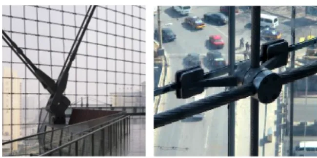
Cable net facades consist of a single-layer, plane, prestressed cable net with the glass panes directly attached to its nodes. Wind loads hitting the net at a 90° angle cause large deformations which can be controlled by prestress of the cables. The surrounding structure has to be able to absorb the net forces. The support of the panes and the cable anchorages have to be designed to allow for large deformations of the net.[7]
The cast stainless steel mounting brackets are manufactured using ceramic moulds. They hold the glass panes at the four corners, requiring no drilling of the glass, and are clamped to the cables.[8]
According to the Figure 3, the executive system of the facade in cable net has been explained. The upper and lower beams have been designed in order to keep the amount of prestressed loads of cables and they are also used to be a support for vertical cables. The internal forces of beams look almost like a simply support beams and cables as a point load, put pressure on the beams by pinned connection. The vertical cables are prestressed and joined to each other by horizontal cables. The side edges are support to the horizontal cables. In case of using these cables, they must be designed in a way that they have ability to endure the pressures from horizontal prestressed cables.
Figure 3: Load diagram of cable net façade
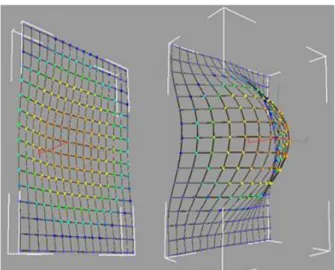
The cable net facade treats like shell structures (Figure 4) and spread any imposed pressures over its surface. And this feature raise the capabilities of the system in front of the pressures derived from earthquakes or winds, and also against pressures due to the natural or terroristic explosions. And in other words, the system destroys the imposed pressures by these features.
Figure5: Deflection of façade
We can infer from the figure 4&5 that when a load is imposed on the cable net facade, the imposed pressure spreads all over the surface so that the amount of this, reaches to its maximum level in the middle part of thesurface of facade (this part is the farthest point from the side supports), but in the edges (in supports) it reaches to its minimum level. For better understanding, we can mention a state in which a piece of cloth deforms under the pressure of something like a globe. Cloth begins to deform in the middle of the conjunction created by the diagonals from the corners and reaches its optimum in front of the imposed pressure. At this time, the deformation abates and in the recessive state, the cloth will show reaction and hurl the globe exactly at the opposite side of it. But the way in which the burden affects on the cable net facade will have a deep impression on designing of the connective nodes in cables. Because the type of connection type between structural frame to panel, it's subdivided in to two parts:
1. The point fixed systems 2. The continuously fixed system.
Continuously fixed systems are formed by the use of mechanisms that consist of pasted/glued and/or compressed based fixing mechanisms to connect the glass lite to structural frame. But in the Point fixed systems, the panels are fixed together without using metal frames or mullions. The system allowed designers to glaze large openings in buildings, to create light and space with a minimum of visual barriers [9].
But the more speculative thing is the kind and the methods in which the panels connect to the façade, and also the connection between the facade structure and the main structure. At first, the pressure imposes to the panels of facade from outside. Then, it is transferred to the facade structure by nodes, and finally, from this structure to the main one. As for our selection of cable structure in order to increase flexibility and also to raise the output of materials, we can conclude from the issue that the kind of load over the facade structure may work in "spot" mood. The nodes play the main role in the cable net facade. Because the major part of the pressures over the facade structure is initially imposed by the nodes. Therefore, the cycle of transferring energy begins. Because the connection between the facade and the main structure is pinned connections, so in the cable structures, the most important part of designing is connectors. Because the pressures act in axial mood and the secondary pressures do not have any effects on the designing of facade. For this reason, the accountant engineers pay more attention on the nodes.
The cable net facade has two kinds of connections:
1. The connection between cables and terminal beams. 2. The inter-cable connection. the first one is pin and regular, but the second one is a fixed connection that joins two separate parts from the cable net structure and the facade panels. Due to the fact that the transformation made in the facade is mainly occurs in the points of conjunction among cables and the panels of facade, so they must be taken in to consideration more and more. In this step of designing, we could contrive to use the pressures over the façade[10].
Different nodes are designed to connect the cables with each other. They are mainly fixed, because of transferring energies. But what's important here is the development of a node that decreases or at least controls the relocation rate of the cables caused by imposed pressures. There are many solutions to this
issue. One of which is the usage of the reactionary system to control the pressures in the knot. There are some reactionary factors including:
1. The springs.
2. The reactionary materials like plastics.
We can also mention the cases that are used in the designing of the nodes, like hydraulic systems created to resist against the imposed pressures from earthquakes to the building.
HYDRAULICS SCIENCE AND THEIR APPLICATION IN BUILDINGS:
The word "hydraulic" is derived from a Greek word "hydro" that means the flow of liquid substances. Shortly, it can be described as a technique that transfers and converts energy through liquids.
About 6,000–7,000 years ago, farming villages of the Near East and Middle East became urban centers. During the Neolithic age (ca. 5700–2800BC), the first successful efforts to control the flow of water were driven by agricultural needs (irrigation) and were implemented in Mesopotamia and Egypt [11]. The development of hydraulic technology has been traced, beginning with its infancy in the development of irrigated agriculture and water supply for urban centers. We have looked at some of the major advances that occurred in hydraulic technology during antiquity (before the end of the Roman Empire), long before the development of the laws of conservation used in modern day design of hydraulic structures. Considering the hydraulic structures that were built by the ancients, they had a remarkable observation of nature and were able to draw conclusions from their observations [12]. Nowadays, the science of hydraulic has a great effect on all scientific fields, so that in recent years, its impression on construction industry is quite outstanding.
The basis for all hydraulic systems is expressed by Pascal's law which states the pressure exerted anywhere upon an enclosed liquid is transmitted undiminished, in all directions, to the interior of the container. This principle allows large forces to be generated with relatively little effort.
Figure 6: Pascal’s Law apparatus
In construction industry, the science of hydraulic is mainly used to convert the big imposed pressures like earthquakes in to the smaller pressures. So that, it could control the great vibrancies. Viscosity damper is one of them. In the Dampers, the energy is absorbed by sticky oil inside the cylinder. These tools use the hydraulic system to control vibrancies.
But what is focused and explained in this essay, is the usage of the hydraulic science to convert small energies like wind in different measure to big ones, whose abilities can change and produce the required energies. Therefore, we try to use the cycle of hydraulic system and subsequently find an appropriate solution in which, by using the vibrancies produced through the imposed energies like wind, we can supply some of the required energies for building. This system is mainly used in mechanics. For example, in the vehicle manufacturing industry and the hydraulic jacks. So, at first the entire cycle of hydraulic system is studied.
Figure7: hydraulic system in vehicles
As you can see, in spite of the fact that the hydraulic system in vehicles is a little sophisticated, but it completely matches the things we desire in the building facade issues[13]. The hydraulic system is consisted of the ingredients below:
1. The cylinder. 2. The Check ball.
3. The regulator of pressure. 4. The pump.
5. The engine. 6. The tank. 7. The filter.
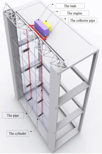
Cylinder and engine are some of the most important parts in the process of hydraulic system. Because they are directly related to the places where the pressures are applied. Accordingly, our argument about the development of hydraulic system in facade should be focused on this matter. In the cable net facade, the part of cylinder is the same as the connected parts of cables and the panels of facade, so that the wind and other imposed pressures create our propulsion. But what's clear is that the cylinder is fixed. So, it should be placed in a way that be kept without any movement in the terminal points. Because of the fact that the cable net structure in the facade is chosen, so the required preparations should be made to contrive the mentioned cylinder in the right place. Because the cable net structure has just single layer, so an extra layer is needed. The reason is that the initial and the terminal points of the extra layer must not match the identical points in the structure of the facade. In the system, the cable net structure has two layers that the inner one is used to maintain the constancy and stability of the interior panels. Because the movements made by the imposed pressures to the exterior layer of the façade, and "dampers" control these pressures and would not let them move toward the interior layer. By using this system, the safety and the convenience of the habitats will be spectacularly guaranteed. In Figure8, the function of the facade against the imposed pressure is shown.
The inneer and the outer layers are linked to each other by a mid-element. But in order to control the imposed pressures, we can enjoy the function of the dampers.
Figure9:Schematic diagram of fluid viscous damper
The dampers are mainly used to control the vibrancies derived from earthquake in building. According to the kind and the direction of the imposed pressures, the dampers have different subdivisions. One of these divisions is based on the function of cylinders. The placement of a cylinder head among the hydraulic fluid is the prevalent system of damper. Because the movements in earthquakes are sweeping, so they must be controlled in different directions. These kinds of dampers have single action cylinders. But in the system that is required in the cable net facade, the pressure is transferred from outside of the building. In this case, we need an open system to reach our goals in designing. So, "the accumulator housing" is deleted and attached to the total hydraulic system of facade. The single action cylinders impose pressures in just one direction, and it occurs only when the oil enters in to the cylinder by pumping. These cylinders do not have any hydraulic return and consequently, it will happen by gravity or the recurrent power of the spring to come back to the status quo. The single action cylinders are the most simple linear operators in function. The body of these cylinders is a kind of shaft-shaped shield in which the piston bar is placed in one side, and the oil entrance is placed in another side of it. In order to caulk the piston over cylinder well, the surface of the interior layer is precisely done and elostomery flood gates or metal rings are used for caulking. There is a small duct at the end of the cylinder that evacuates the probable leakage from the side wall of the piston. and if this duct is closed, the length of the course of cylinder will decrease. Some of these cylinders are called "ram". They have some piston bars in large diameters and are used to lift heavy loads. These cylinders are used in the buffer systems, the hydraulic presses and the automobile lifter jacks (Figure10).
This kind of cylinder has a spring to return back the cylinder head to its status quo. This spring has also the power to resist against the movement of outer layer of the facade toward the outside of the building.
Figure10: single action cylinder
In this step, the pressure is transferred to the hydraulic oil by the cylinder head attached to the outer layer of facade. The pressure is moved and flowed in to the system by a hole that is clung to the hydraulic net facade. The hole attached to the both cylinder and hydraulic net, has a control tap for flowing that controls the flowing of fluids in the hydraulic net. There are different kind of taps that can control the pressure of oil, to specify the direction of flowing and also has ability to shut off the system in case of probable errors. There are also simple kind of control taps having two holes that are attached to a one-sided switch that let the fluid come in or vice versa by controlling the existing pressure. After entering the hydraulic oil in to the cycle, its transference is done through pipes that have required resistance against the burden and the erosion due to the flowing. In order to have enough constancy, this pipe is connected to the cable of inner layer of the facade by holders.
Figure 11: conction of pipe and cylinder
But the pipes must transfer the hydraulic oil to the last part to complete the cycle of the hydraulic system. At first, we need a tap to control pressure in the place where the pipe is connected to the tank. This tap looks like the one that was in the place where the pipe and cylinder met each other. The tank is at the end of the facade and acts like the collector. The tank collects all of the hydraulic fluid to be able to produce the required energy. The tank has an entrance and an exit duct with a generator engine. This part of designing is directly based upon the used system of engine.
Figure 12: entire hydroulic system
In this step of designing, all of the hydraulic oil is gathered in the tank. Now, the produced energy can reproduce a greater energy to be used in the generator engine in different ways. The required energy can enter in to the engine directly. For example, the hydraulic system of an automobile is just one of these kinds that directly start up the gears inside the engine. So, we need a pump to transfer the hydraulic fluid in to the cycle of hydraulic facade. But occasionally, the energy produced by the pressure of hydraulic oil is changed in to the mechanical power and subsequently this power can start the engine.
For example, the produced energy is finally connected to the cylinder and make it move by creating a pressure zone. This process can be easily seen in the hydraulic lifters or other similar systems (Figure 13).
Figure 13: Functional hydroulic syatem
In this case, we don’t need any pump, and the energy is transferred in to the engine through the terminal pistons. Automobile crank shafts are indeed clear examples that gain their powers from the cylinders[14].
Figure 14: Function of end of system
According to the requirements and also the styles of other interested engineers, the end of the system is mainly variable. But the most important thing is the tap that controls the pressure. It's located in the entrance of the pipe in to the tank to control the system generally. It's located in the entrance of the pipe in to the tank to control the system generally.
RESULTS AND DISCUSSION
It can be inferred from the passage that the hydraulic system has a great adaptation in the designing of building facade and can be used to increase the productivity of the curtain wall facade system. Some of the general features of the project are presented in the following table.
Table1:Kind of Curtain Wall Facade Double skin façades 1.Number of skin
Combined systems 2.System components and
the relations in between
Point fixed systems (Kind of damper system)
3.Connection type between structural frame to panel
Semi panel system 4.Type of installation
Cable net 5.Type of curtain wall
structure
The used cable net facade are more heavy than the cable net facade in the single skin form. But in order to develop a terminal beams to make a hydraulic connection between two layers, there should be an extra inner layer. On the other hand, this system has less energy waste and the users feel safety more
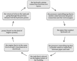
and more. and finally, we can divide the entire hydraulic system used in the facade in to the parts below(Figure 15):
1. the hydraulic-piston connection between two layers.
2. the pressure controlling tap that is double-sided between the pistol connection and the vertical pipes. 3. the pipes that conduct hydraulic oil.
4. the pressure controlling tap that is double-sided in connection between pipes and tank. 5. the tank that is placed on the highest point of the building.
6. the engine that is in the same level as tank’s (mechanical or electrical). 7. pump (based on the kind of engine system)
8. the return of oil in to the tank and going through the previous distance till the hydraulic piston.
Figure 15: Instruction of hydraulic system function CONCLUSIONS
In constructions, the hydraulic science, the lifters and the resistant systems against earthquake take most of the specialists' attention to themselves. The high costs of designing and the administration of this system is just one of the reasons. But it is quite obvious that the usage of hydraulic system in building facade is somewhat justifiable. Because it can supply some of the required energies for building. On the other hand, it will result in increasing the stability and the resistance of building facade in front of different pressures. In this system, the loss of energy has decreased, the safety factor has increased and finally it provides the habitats' convenience. All of the vibrancies are controlled by the outer layer and the hydraulic connections in the farthest side from the residence span.
Also, we can easily control the building facade by this system. One of the advantages of the system is “dynamic façade”. Because the panels of facade can be led and moved in any direction by using the pressure control of hydraulic oil. Generally, these advantages can raise the application of the hydraulic science in constructions in big deals, and can resolve most of the designing limitations.
REFERENCES
[1]. Yusuf Ýlhan, Murat Aygün, 2006, “Constractional classification of continuously and point fixed curtain wall system”, 1st International CIB Endorsed METU Postgraduate Conference Built Environment & Information Technologies, Ankara, , pp569-579.
[2]. Tillmann Klein, 2013, Integral Facade Construction: Towards a new product architecture for curtain walls, TU Delft, ISSN 2212-3202.
[3]. MICHAEL J. CROSBIE, 2005, Curtain walls, Birkhäuser Architecture; 1 edition, Printed in Germany, ISBN-13: 978-3-7643-7083-1.
[4]. Heino Engel, 2007, Structure Systems, ISBN-13: 978-3775718769.
[5]. G. schierle, 2007, Structure in Architecture, Modern steel construction, ISBN 0181965097
[6]. Ruo-qiang Feng, Lin-lin Zhang, Yue Wu, Shi-zhao Shen, 2009, “Dynamic performance of cable net facades”, Journal of Constructional Steel Research 65, pp2217-2227.
[7]. J. SCHLAICH , H. SCHOBER , 2002, “Design principles ofF glass roofs”, Lightweight structures in civil engineering, June, Warsaw, Poland , 24-28.
[8]. Hans Schober, 2007, “Steel casting in architecture and engineering, advances in construction materials” , pp 83-108
[9]. BUTTON, D. and PYE, B. ,1993 , Glass In Building: Guide to Modern Architectural Glass Performance, Butterworth Architecture, Oxford.
[10]. Karol Kazmierczak, 2010, “Review of curtain walls, Focusing on design problems and solutions, Design and Rehabilitation - Session EE4-1.
[11]. Larry W. Mays, 2008, A very brief history of hydraulic technology during antiquity, Department of Civil and Environmental Engineering, Arizona State University, Tempe, AZ 85287-5306, USA, Environ Fluid Mech 8: 471–484
[12]. Fahlbusch H.,2004, “the archaeology of water in the Middle East”, International Symposium held at Petra, Wadi Musa (H.K. of Jordan),pp 15–20,
[13]. Research of TORO University, Hydraulics circuits, components, schematics, hydrostatic drives and test equipment, PART NO. 09169SL.
[14]. Andrew Parr MSc., 2006, CEng., MIEE, MlnstMC, Hydraulics and Pneumatics A technician's and engineer's guide, ISBN - 13:978-0-7506-4419-9.