GRADUATE SCHOOL OF NATURAL AND APPLIED SCIENCES
A PRACTICAL AND FORMAL ANALYSIS OF
DISTRIBUTED PRIVATE KEY GENERATION FOR
IDENTITY BASED CRYPTOGRAPHY
G¨orkem KILINC
¸
Thesis Advisor: Assoc. Prof. Ahmet Hasan KOLTUKSUZ, Ph.D
Department of Computer Engineering
Bornova-˙IZM˙IR June 2012
K˙IML˙IK TABANLI KR˙IPTOGRAF˙IK S˙ISTEMLER
˙IC¸˙IN DA ˘
GITIK G˙IZL˙I ANAHTAR ¨
URET˙IM˙IN˙IN
˙IS¸LEVSEL VE B˙IC¸˙IMSEL AC¸IDAN ˙INCELENMES˙I
KILINC
¸ , G¨orkem
Y¨uksek Lisans Tezi, Bilgisayar M¨uhendisli˘gi B¨ol¨um¨u Tez Danıs¸manı: Doc¸. Dr. Ahmet Hasan KOLTUKSUZ
Haziran 2012, 77 sayfa
Temelleri gizlilik paylas¸ımı y¨ontemlerine dayanan da˘gıtık gizli anahtar ¨uretimi(DGA ¨U) kriptografide gizli anahtarların da˘gıtık olarak g¨uvenli bir s¸ekilde ¨uretilmesi amacıyla kullanılmaktadır. DGA ¨U kullanımına en uygun olan kriptografik sistemlerden bir tanesi kimlik tabanlı kriptografik sistemdir. DGA ¨U kullanımı, kimlik tabanlı krip-tografik sistemlerde var olan ve sistemin pratik olarak kullanımında engel tes¸kil eden anahtar emaneti probleminin bir c¸¨oz¨um¨u olarak bilinmektedir. Her ne kadar bilinen matematiksel problemler ¨uzerine oturmus¸ olsa da, ¨ong¨or¨ulmeyen ac¸ıklar ic¸erebilece˘gi ic¸in protokol¨un do˘grulanması c¸ok ¨onemlidir. Bu tezde, DGA ¨U pro-tokol¨un¨un hem is¸levsel hem de bic¸imsel ac¸ıdan analizi hedeflenmis¸tir. Bu amac¸la ¨oncelikle DGA ¨U protokol¨u, end¨ustriyel kontrol sistemleri ¨uzerinde b¨uy¨uk ¨olc¸¨ude kullanılmakta olan SCADA protokol¨unde eksik olan kimlik denetimi sa˘glanarak g¨uvenli hale getirilmesi ic¸in uygulanmıs¸tır ve is¸levsel analiz bu uygulama ¨uzerinde yapılmıs¸tır. Bic¸imsel (formal) analiz ic¸in ise protokol basit Petri a˘gları kullanılarak modellenmis¸tir. Daha sonra bu model ¨uzerinde yapısal ve davranıs¸sal analizler yapılarak protokol¨un bic¸imsel olarak do˘grulanması ic¸in gerekli g¨uvenlik ¨ozellikleri ispatlanmıs¸tır.
Anahtar Kelimeler: Da˘gıtık Gizli Anahtar ¨Uretimi (DGA ¨U), Kimlik Tabanlı Krip-tografi, End¨ustriyel Kontrol Sistemleri, SCADA, Basit Petri A˘gları, Bic¸imsel (For-mal) Analiz, Kriptografik Protokollerin Bic¸imsel (For(For-mal) Do˘grulaması.
A PRACTICAL AND FORMAL ANALYSIS OF
DISTRIBUTED PRIVATE KEY GENERATION FOR
IDENTITY BASED CRYPTOGRAPHY
KILINC
¸ , G¨orkem
M.Sc. in Computer Engineering
Supervisor: Assoc. Prof. Ahmet Hasan KOLTUKSUZ, Ph.D June 2012, 77 pages
The basis of distributed private key generation (DPKG) scheme lies on secret shar-ing and it has been used in cryptography for generatshar-ing keys distributively and se-curely. One of the most suitable cryptographic system for DPKG is identity based cryptographic system. DPKG is enormously used for generating private keys for the clients of an identity based cryptographic system. The scheme is claimed to be a solution for the key escrow problem which exists in the identity based cryptogra-phy and leads to impractical cryptographic systems. It is highly important to verify the protocol even though the protocol lies on well known mathematical problems. Clearly, the protocol might always preserve some unforeseen flaws. In this thesis, we aimed to analyze DPKG protocol in both practical and formal manners. For this aim, we implemented the protocol on industrial control systems (ICS) in order to se-cure the widely used ICS protocol SCADA by providing it with authentication and performed a practical analysis on the implementation. In order to perform formal analysis, we first modeled the DPKG protocol by using elementary Petri nets then we performed structural and behavioral analysis on the model for proving essential security properties of the protocol with the eventual aim of formal verification. Keywords: Distributed Private Key Generation (DPKG), Identity Based Cryptogra-phy, Industrial Control Systems, SCADA, Elementary Petri Nets, Formal Analysis, Formal Verification of Cryptographic Protocols.
Acknowledgements
First and foremost, a very special thanks is due to my supervisor, Assoc. Prof. Ahmet Koltuksuz, Ph.D for his invaluable guidance, patience and encouragement. I feel very fortunate for having had the chance to work with him. He is such an exceptional advisor that I will always be honored to be his student.
I also want to present my sincere thanks to European Commission Joint Research Centre (JRC), Ispra. An important part of the work has been done during the year I spent there as a trainee. Many thanks for the opportunity.
I would like to thank Carlo Ferigato, Ph.D who introduced me with Petri nets and Igor Nai Fovino, Ph.D. They had been devoted advisors to me during my traineeship in JRC. I am enormously thankful to them for their still-continuing support from overseas.
I owe my deepest gratitude to Asst. Prof. Serap S¸ahin, Ph.D who has always stood by me with her never ending support, guidance and positive energy. She was the one who uplifted me during the hard times.
Many thanks go to Asst. Prof. H¨useyin Hıs¸ıl, Ph.D for his huge support. He helped me study abstract algebra, elliptic curves and cryptographic pairings which formed an important part of the mathematical basis for my study.
I also want to express my appreciations to my dear friends and classmates Burak Ekici and C¸ a˘gatay Y¨ucel. For many years we have studied together and they have been always very helpful and supportive.
Last but not the least I owe more than thanks to my mother S¸eng¨ul Kılınc¸, my father Hasan Kılınc¸, and two very special and valuable people in my life; Egemen Soylu and Burcu Ezgi ¨Ozdemir. They have always believed in me and supported me. Without them I might never have finished this thesis.
I declare and honestly confirm that my study titled “A Practical and Formal Anal-ysis of Distributed Private Key Generation for Identity Based Cryptography”, and presented as Master’s Thesis has been written without applying to any assistance in-consistent with scientific ethics and traditions and all sources I have benefited from are listed in bibliography and I have benefited from these sources by means of mak-ing references.
11 / 06 / 2012
Contents
¨
Ozet v
Abstract vi
Acknowledgements vii
Text of Oath viii
List of Figures xi
1 Introduction 1
1.1 Motivation and Related Work . . . 1
1.2 Roadmap . . . 2
2 Identity Based Cryptography and Distributed Private Key Generation 5 2.1 Mathematical Background . . . 5
2.1.1 Preliminaries . . . 5
2.1.2 Elliptic Curve over a Finite Field . . . 8
2.1.3 Cryptographic Pairings . . . 9
2.1.4 Verifiable Secret Sharing . . . 12
2.2 Identity Based Cryptography . . . 12
2.2.1 Encryption . . . 13
2.2.2 Signature . . . 14
2.2.3 Key Escrow Problem . . . 15
2.2.4 Distributed Private Key Generation . . . 15
2.2.5 Setup . . . 15
2.2.6 Distribution . . . 16
2.2.7 Extraction . . . 20
3 An Implementation and Practical Analysis of Distributed Private Key Generation for Identity Based Cryptography 23 3.1 Distributed Private Key Generation Implementation . . . 23
3.2 Case Study: Implementing DPKG on Industrial Control Systems . . 24
3.2.1.2 Modbus Vulnerabilities . . . 27
3.2.1.3 Distributed Identity Based Secure Modbus . . . . 28
3.2.2 Prototype Overview. . . 29
3.2.3 Experimental Tests . . . 31
3.2.3.1 Distribution . . . 31
3.2.3.2 Extraction . . . 32
3.2.3.3 Signature & Verification . . . 33
3.2.4 Conclusion for the Case Study . . . 34
4 Using Petri Nets for Modeling and Analyzing Cryptographic Protocols 37 4.1 Introduction to Petri Nets . . . 37
4.2 Modeling with Elementary Petri Nets . . . 40
4.3 Properties of Petri Nets . . . 43
4.3.1 Behavioral Properties. . . 43
4.3.2 Structural Properties . . . 44
4.4 Analysis of Elementary Petri Nets . . . 45
4.5 Modeling and Analyzing Cryptographic Protocols with Elementary Petri Nets . . . 46
5 Formal Model of Distributed Private Key Generation for Identity Based Cryptography 49 5.1 Modeling Distributed Private Key Generation for Identity Based Cryptography . . . 49
5.1.1 Modeling Overall Distributed Private Key Generation and Analysis of the Model . . . 49
5.1.2 Model of Setup and Distribution Step . . . 50
5.1.3 Model of Key Extraction Step . . . 53
5.1.4 Analysis on the DPKG model . . . 55
5.1.5 Intruder Model . . . 56
5.1.6 Analysis on the Intruder Model . . . 58
6 Results and Conclusion 61
List of Figures
2.1 Addition on an elliptic curve . . . 9
2.2 Identity based encryption scheme . . . 13
2.3 Identity based signature scheme . . . 14
2.4 Block schema of the distribution step of private key generation. . . . 18
2.5 Block schema of the extraction step. . . 20
3.1 A typical SCADA system embedded into a turbogas power plant facility . . . 26
3.2 Distribution step . . . 30
3.3 Key extraction step . . . 30
3.4 Distribution phase performance test (Time in ms.) . . . 31
3.5 Key extraction phase performance test (Time in ms.) . . . 32
3.6 Simultaneous answer performance test (Time in ms.) . . . 33
3.7 Time spent for signing and verifying a Modbus package . . . 34
4.1 Demonstration of firing rule: (a) t0is enabled (b) t0is fired . . . 38
4.2 Demonstration of firing rule: (a) t0is not enabled (b) t0cannot fire . 39 4.3 Sequence of events in a Petri net system. . . 40
4.4 Conflict case in a Petri net system . . . 41
4.5 Concurrency of two events in a Petri net system . . . 41
4.6 Case of synchronization in a Petri net system . . . 42
4.7 Two mutually exclusive processes modeled with Petri nets . . . 42
5.1 A net representing simple overall look to the DPKG. . . 51
5.2 Petri net model of distribution step of distributed private key gener-ation. . . 52
5.3 Petri net model of extraction step of distributed private key generation. 54 5.4 Petri net model of an intruder in the distribution step of DPKG. . . . 57
5.5 Petri net model of an intruder in the extraction step of DPKG. . . 58
5.6 The sequence of events for making Formula 5 true. . . 59
Chapter 1
Introduction
1.1
Motivation and Related Work
In 1984, Adi Shamir [1] put forward the idea of identity based cryptography. This cryptographic scheme was not very practical because of the need for a private key generator which is responsible for generating keys for the users. Generating private keys for the user, private key generator can sign or decrypt a message on behalf of any user and it can make users’ private keys public. This problem of identity based cryptography is called key escrow problem. A solution to the key escrow problem was proposed by Boneh and Franklin [2] in 2001. Their solution was distributing the private key generation among multiple private key generators.
On the other side another concept was being developed which is called Petri nets. The concept was first defined by Carl Adam Petri in his Ph.D. thesis in 1960 [3]. Petri net is a powerful modeling tool especially for distributed, concurrent, asyn-chronous systems. It is intensively used for modeling communication and in the last years it is being used for analysis and verification of cryptographic protocols as well. However there is no known Petri net model for distributed private key generation.
Considering all, the aim of the work is to provide a formal model of distributed pri-vate key generation (DPKG) for identity based cryptography, to analyze the struc-tural and behavioral properties, to use model checking methods on the model for more detailed analysis and finally to verify some security properties of DPKG to make a step for the verification of the protocol.
Given the possibility to represent, at the lowest level, the communication flow and for their intuitive graphical presentation, Petri Nets are used ever since for the de-tailed analysis of communication protocols. Starting from the work of Nieh and Tavares [4], Petri Nets have been applied to the analysis of security protocols as well. While in [4] the construction of the model is based on a refinement process involving Place/Transition net systems for the conceptual level and high-level nets for the functional level, in more recent works, almost exclusively high-level nets have been used. For example, in [5], Colored Petri Nets are used for re-discovering known flaws in the Andrew secure RPC protocol while in [6], a special class of composable high-level Petri Nets is used for showing flaws in the Kao-Chow au-thentication protocol. In all of the cases, model checking techniques are applied to the protocol model in order to generate the cases witnessing the flaw in the protocol. In this study, a different approach to model a security protocol is chosen since the application domain, Information and Communication Security (ICS), is quite spe-cific and low level control flow should be represented. Consequently, we decided to model the protocol with low-level nets starting with Elementary Net Systems. In this way, we have at least three advantages: 1) leave the representation open to the inclusion of low-level signal processing; 2) use basic tools for proving structural properties of the model like invariants analysis at the level of basic signals; 3) con-struct abstractions of the model easily by passing to higher-level nets. Moreover, this choice allows for the use of powerful model checking tools like LoLA [7].
1.2
Roadmap
The rest of the thesis is structured as follows.
Chapter 2provides operational description of identity based cryptography and dis-tributed private key generation (DPKG) after giving a brief mathematical back-ground.
Chapter 3presents a practical specification of DPKG for identity based cryptogra-phy. The chapter includes an implementation of DPKG on industrial control sys-tems. In the implementation DPKG is used for generating identity based private keys then these keys are used for performing identity based signature in the aim of providing the system with authentication.
In Chapter 4, after an introduction to Petri nets, the definition and properties of elementary Petri nets are given. In the end of the chapter we discuss how elementary Petri nets are used for modeling and analyzing cryptographic protocols.
In Chapter 5, Petri net models of DPKG are introduced. First, a basic model of the protocol is presented and then an intruder is added into the model. In addition to traditional structural analysis, model checking methods are also used to prove security properties of the protocol.
Chapter 2
Identity Based Cryptography and
Distributed Private Key Generation
2.1
Mathematical Background
2.1.1
Preliminaries
Definition2.1. A group is a pair (G, ∗) where G is a nonempty set closed under the binary operation ∗, such that the following axioms are satisfied:
• ∗ is associative; (P ∗ Q) ∗ R = P ∗ (Q ∗ R), where P, Q, R ∈ G
• There is an identity element e such that; e ∗ P = P ∗ e = P where e, P ∈ G • Each element Q in G has a unique inverse Q′ in G with the property that;
Q ∗ Q′=Q′∗Q = e
Definition2.2. A group G is an abelian group if its binary operation ∗ is commu-tative.
Example2.1. The set Z+is not a group, because there is no identity element in Z+. Example2.2. The set of all nonnegative integers Z+⋃{0} is still not a group. It has an identity element which is 0 but not all the elements in the set has an inverse. Example2.3. The set of integers Z, rational numbers Q, real numbers R and com-plex numbers C with the operation + are abelian groups.
Definition2.3. If G is a finite group, the order of G, denoted by ∣G∣, is the number of elements in G.
Definition 2.4. A subset H is a subgroup of G, if H is closed under the binary operation of G and if H is a group itself.
Theorem2.1. Let G be a group and P ∈ G. Then,
• H = {Pn∣n ∈ Z} is a subgroup of G.
• H is the smallest subgroup of G which contains P. • Every subgroup containing P contains H.
Proof. See [8] page 64.
Definition2.5. The group H of Theorem2.1is the cyclic subgroup of G generated by P and it is denoted as H = ⟨P⟩.
Definition2.6. If ⟨P⟩ = G, P generates group G and P is a generator for G. Definition2.7. A group G is cyclic if some element P of G generates G. Let P ∈ G, if the cyclic subgroup ⟨P⟩ is finite, the order of P is the order ⟨P⟩. Theorem2.2. Every cyclic group is abelian.
Proof. See [8] page 70.
Theorem2.3. A subgroup of a cyclic group is cyclic.
Proof. See [8] page 72.
Discrete Logarithm Problem. Let (G, ×) be a cyclic group of order n and let P be a generator of it. The Discrete Logarithm Problem (DLP) for G is to find the unique ksuch that; Q = Pk= ktimes ³¹¹¹¹¹¹¹¹¹¹¹¹¹¹¹¹¹¹¹¹¹¹¹¹¹¹¹¹¹·¹¹¹¹¹¹¹¹¹¹¹¹¹¹¹¹¹¹¹¹¹¹¹¹¹¹¹¹¹¹µ P × P ×. . . × P (2.1) where Q ∈ G and 0 ≤ k ≤ n − 1.
Note that it becomes finding k such that kP = Q if the group is defined additive. k exists since P is a generator of the group.
The complexity of finding k depends on the selection of the group and the binary op-eration. Discrete Logarithm Problem (DLP) is used as an underlying hard problem in many cryptographic protocols (i.e. Diffie Hellman Key Exchange Protocol).
Diffie Hellman Problem. For arbitrary k, m, r, Diffie Hellman Problem is closely related to DLP. Given P, Pk and Pm, finding Pkm is called Diffie Hellman Problem
(DHP). For certain groups it is assumed that the DHP is hard. Computing Pkm is
also referred as Computational Diffie Hellman Problem (CDHP) in order to sepa-rate it from Decisional Diffie Hellman Problem (DDHP) which is the problem of distinguishing between the distributions ⟨P; Pk; Pm; Pkm⟩and ⟨P; Pk; Pm; Pr⟩.
Definition2.8. A set F together with two operations, which are addition (denoted by +) and multiplication (denoted by ⋅) is said to be a field if it satisfies the following properties;
• (F,+) is an abelian group with additive identity element denoted by 0.
• (F/{0},⋅) is an abelian group with multiplicative identity element denoted by 1.
• (P + Q) ⋅ R = P ⋅ R + Q ⋅ R for all P, Q, R ∈ F.
If F has finite number of elements then F is said to be a finite field.
Field Operations. A field is equipped with addition and multiplication. The other operations are done by means of these two operations. Subtraction is defined by means of addition as P − Q = P + (−Q) where P, Q ∈ F. −Q is the negative of Q which is the unique element in F such that Q + (−Q) = 0. Division is defined by means of multiplication. Let P, Q ∈ F and Q ≠ 0. P/Q = P ⋅ Q−1 where Q−1 is the inverse of Q which is a unique element in F such that Q ⋅ Q−1=1.
Definition 2.9. There exists a finite field F of order q if and only if q is a prime power such that q = pnwhere p is a prime number and n ∈ Z+. If n = 1, F is called a prime field and denoted by Fp. The prime p is the modulus of Fp. If n > 1, the field
F is said to be an extension field.
Example2.4. In the following there are some examples of arithmetic operations in prime field F13.
• Addition: 12 + 3 = 2, (15 mod 13 = 2) • Multiplication: 5 ⋅ 4 = 7, (20 mod 13 = 7) • Subtraction: 8 − 11 = 10, (−3 mod 13 = 10) • Inversion: 4−1=10, ( 4 ⋅ 10 mod 13 = 1)
2.1.2
Elliptic Curve over a Finite Field
The idea of using elliptic curves for cryptography was put forward independently by N. Koblitz [9] and V. S. Miller [10] in 1985. The security of elliptic curve based cryptographic systems depends on easy calculation of point multiplication on an elliptic curve and inability to compute multiplicand back knowing resulting point and the beginning point.
Simply, an elliptic curve is a cubic curve defined over two variables. Every elliptic curve can be represented in Weierstrass form (2.2). As it can be defined over real numbers, it can also be defined over a finite field.
Let p be a prime number and Fpa prime field, elliptic curve E over prime field Fp,
denoted by E(Fp), can be defined by the following equation;
y2=x3+ax + b (2.2)
where a, b ∈ Fpshould satisfy 4a3+27b2≡/0( mod p). An elliptic curve can be used
to form a group. Let x, y ∈ Fp, a pair (x, y) is a point on the curve if it satisfies the
equation. On an elliptic curve, there is also a special point called point at infinity which is denoted by ∞ or O.
An elliptic curve group over Fpconsists of the points on the corresponding elliptic
curve, together with the point at infinity and a properly defined addition operation. Informally, the addition operation is defined in the following way; suppose that P and Q are two distinct points on an elliptic curve. In order to add P and Q, a line is drawn through these two points. This line will intersect the elliptic curve in another point, −T . When we draw a perpendicular line to the x-axis we will find reflection of point −T which is T . T is the resulting point as T = P + Q.
With this addition rule, the set of points E(Fp) forms an additive abelian group whose identity element is the point at infinity and each element P has its inverse −P such that;
f or P = (x, y) and −P = (x, −y), it is written,
FIGURE 2.1: Addition on an elliptic curve
Elliptic Curve Discrete Logarithm Problem. Let E be an elliptic curve defined over a finite field Fp. Let P and Q be points in E(Fp). Finding an integer m ∈ Z+ such that;
Q = mP
is called the Elliptic Curve Discrete Logarithm Problem (ECDLP). The complexity of ECDLP depends on the selection of the curve. There are different algorithms to calculate the discrete logarithm. The fastest known algorithm to solve ECDLP in E(Fp)takes approximately
√
psteps [11].
2.1.3
Cryptographic Pairings
Bilinear pairings are used in many cryptographic applications such as Boneh and Franklin’s identity based encryption scheme [2]. The main idea of using pairings in cryptography is to construct a mapping between two groups which provides a reduction of one problem in one group to an easier problem in the other group. The most well known cryptographic pairings are the Weil pairing and the Tate pairing. Let p be a prime, G1 and G2 be additive cyclic groups. Suppose that the order of
G1and G2are p and G3is a multiplicative cyclic group of order p then a pairing is
a map as :
Note that G1and G2can also be the same groups.
Definition2.10. Let G1 and G2 additive groups of order p with identity O. Let G3
is a multiplicative group of order p with identity 1. If the following properties are correct for all P, P′∈G1and all Q, Q′∈G2then e is said to be bilinear pairing:
• e(P + P′, Q) = e(P, Q) ⋅ e(P′, Q) • e(P, Q + Q′) =e(P, Q) ⋅ e(P, Q′) • e(mP, Q) = e(P, Q)m
In addition to bilinearity, if there is an efficient algorithm to compute e(g1, g2)for
any g1∈G1, g2∈G2and if e is non-degenerate which means the map does not send
all pairs in G1×G2 to unity in G3, then e is called admissible bilinear pairing.
Admissible bilinear pairings are preferred in cryptographic systems because it is efficient to compute and hard to invert.
Pairings are also used over elliptic curves since they can be used to form groups as mentioned in2.1.2. A pairing function maps a pair of points in one elliptic group to some elliptic curve group.
Definition2.11. Let E be an elliptic curve defined over a field K0then the set
µn= {u ∈ (K0)∗∶un=1 } (2.4) is called nthroot of unity set.
(K0)∗=K0− {0} (2.5)
where K0is a field, K0∗is the multiplicative group of K0, K0is the algebraic closure
of K0and (K0)∗is the multiplicative group of K0.
Let K = K0(µn)be the extension of K0 generated by the nth root of unity. n-torsion
of E(K) is defined as;
E(K)[n] = {P ∈ E(K) ∶ [n]P = O}. (2.6)
E(K) = {(x, y) ∈ K × K ∣ y2=x3+ax + b} ∪ {O}. (2.7) Tate Pairing. Let Fqbe a finite field with q = pnelements where p is prime and E
be an elliptic curve defined over Fq. The identity of E is denoted by O.
Consider a large prime r such that r ∣ #E(Fq)and let k be the smallest integer such
that r ∣ qk−1 with r2∤qk−1.
If all conditions defined above are satisfied then
E[r] ⊆ E(Fqk) (2.8)
where k is called embedding degree or security multiplier. When the embedding degree gets bigger, known algorithms for solving DLP in Fqk gets slower.
Let f be a function on E then the intersection function of f and elliptic curve E can be defined as:
div( fr,p) =r(P) − r(O) (2.9)
or
div( fr,p) =s(P) − ([s]P) − (s −1)(O) (2.10) where fr,pdefines a function which is having s roots on point P and div( fr,p)shows
the points on f which intersect E.
Let P ∈ E(Fqk)[r]and Q ∈ E(Fqk)then Tate Pairing t(., .) is defined as;
t(P, Q) ∶ E(Fqk)[r] × E(Fqk) rE(Fqk) →µr (2.11) (P, Q) ↦ fr,p(Q) qk−1 r (2.12) where rE(Fqk) = {[n]P ∶ P ∈ E(K)} (2.13)
The Tate pairing is well defined, bilinear, non-degenerate and efficiently computable. See Miller’s algorithm [12] for computing the Tate pairing.
The Weil pairing [13] [12] is another bilinear pairing which is used in Boneh and Franklin’s Identity Based Encryption scheme [2] which relies on Bilinear Diffie Hellman Problem.
Bilinear Diffie Hellman Problem. Let G1, G2 be two groups of prime order q.
Let e ∶ G1×G2→G3 be an admissible bilinear map and let P be a generator of
G1. The Bilinear Diffie Hellman Problem (BDHP) in ⟨G1; G2; e⟩ is computing
W = e(P, P)kmr∈G
2while ⟨P; Pk; Pm; Pr⟩for some k, m, r ∈ Z∗qare given.
DDHP in G1is easy and cannot be used to build cryptographic systems while CDHP
can still be hard. The security of Boneh and Franklin’s Identity Based system is based on BDHP which is a variant of CDHP. BDHP is hard in some certain groups, see [2].
2.1.4
Verifiable Secret Sharing
Secret sharing is a method of distributing a secret among multiple players as no player knows the whole secret but each player has a share for the secret. The secret can be reconstructed only if a sufficient number of shares are retrieved. In 1979 Shamir put forward a scheme called (n, k) threshold scheme [14]. The scheme is based on polynomial interpolation. Given k points in the form (xi, yi) where each xi
is distinct , there is only one polynomial f (x) of degree k − 1 such that f (xi) =yifor
all i.
Verifiable secret sharing was first introduced by Chor, Goldwasser, Micali, and Awerbuch in 1985 [15]. In such a scheme each player can verify its share. Feld-man’s verifiable secret sharing scheme [16] is based on Shamir’s scheme and it improves Shamir’s scheme by including verifiability. By using a verifiable secret sharing scheme any dishonest or malicious node in the system can be found.
2.2
Identity Based Cryptography
In an identity based cryptographic system, unlike the other public key cryptographic systems, a publicly known string such as e-mail address, domain name, a physical IP address or a combination of more than one strings is used as public key. Shamir’s
scheme enables users to communicate securely and verify signatures without ex-changing any private or public key. Consequently, there is no need for a certification authority to verify the association between public keys and users.
In 2001, Boneh and Franklin devised the first practical implementation of such an Identity-Based Encryption scheme [2]. Their approach uses bilinear maps and relies on the BDH Assumption.
2.2.1
Encryption
Encryption using identity based cryptography works as in Figure2.2. Node A wants to send an encrypted message to node B. In order to encrypt the message M, instead of asking for B’s public key it uses the identity string which defines B. H is a hash function, which is known by each node in the system and used for creating public keys of equal length and same form from the id strings. It is important to note that, A can perform the encryption even if B doesn’t have its private key yet. After receiving the cipher-text C, B can use its private key to decrypt the message if it already has its private key. Otherwise, B asks to the private key generator (PKG) for its private key. PKG generates the private key dIDB for node B using hashed value
of B’s identity string H(IDB)and the master private key s.
2.2.2
Signature
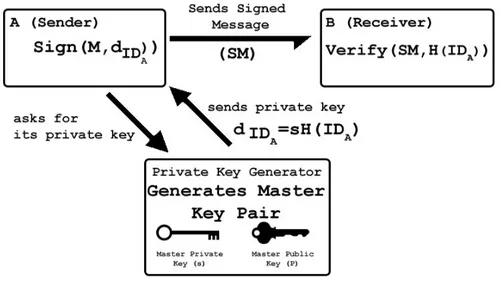
Figure 2.3 shows how the identity based signature scheme works. When node A wants to send a signed message to node B, it uses its own private key to sign the message. It is worth to note that, if it doesn’t have, node A should ask private key generator for its private key to be able to sign a message. Private key generation is the same as it is in the encryption - decryption scheme.
After receiving the signed message SM, node B can use the hashed value of A’s identity string to verify the signature. Verification of the signature doesn’t require any certification authority or other trusted third parties.
Private key generation is only performed in such cases like the establishment of the system, adding a new node to the system, when a renewal is needed, etc.
FIGURE2.3: Identity based signature scheme
In section 3.2 an implementation of identity based signature on industrial control systems is presented. The possibility to provide the low level devices of Super-visory Control And Data Acquisition (SCADA) infrastructures with a mechanism allowing to obtain automatically a private key for signing their own network packets while limiting at the minimum interactions with the external world to verify a signed packet, is extremely appealing. Since each entity in a SCADA system already has a unique identity string known by everyone in the system (e.g. the PLC id for the low
level components and, eventually the MAC address for the SCADA servers), iden-tity based cryptography is a very useful and suitable scheme to provide authenticity, integrity and confidentiality for SCADA systems.
2.2.3
Key Escrow Problem
Although an identity based cryptographic system does not require a certification authority, there is a need for a PKG. Basically, a trusted third party signs user’s publicly known string using the master private key in order to generate a private key for the user. Since the PKG can generate private keys for users, it can sign or decrypt messages of any user or it can make users’ private keys public. This problem about private key generation is called key escrow problem. Distributed private key generation (DPKG) is one of the solutions to the key escrow problem. In both schemes described in [2] and [17], secret sharing methods are used for distributing private key generation among multiple PKGs.
2.2.4
Distributed Private Key Generation
As it is explained in section 2.2.3 the problem to be solved about identity based scheme is the key escrow problem. In this thesis, in order to eliminate the problem, a completely distributed private key generation scheme is performed. In this scheme, a number of PKG nodes participate while they share the responsibility equally. The private key generation scheme consists of three steps: setup, distribution and extrac-tion. A bulletin board, n PKG nodes and clients who need to have private key are the players in the distributed private key generation process. Algorithms presented here are based on schemes described in [17], [2] and [16].
2.2.5
Setup
This step is a preparation step to create the system parameters and to get ready for creating the master key pair distributively and extraction of private keys. It is performed by the bulletin board application. The algorithm for setup phase of DPKG is displayed in the algorithm1.
To perform the setup for DPKG, given K as the security parameter, a prime q of size Kis selected. An elliptic curve group G of order q and a cyclic multiplicative group
Algorithm 1 Bulletin Board setup
Require: security parameter K and cryptographic hash function H ∶ {0, 1}∗→ G∗
1: q ←generate prime of size K
2: G ← choose elliptic curve group of order q
3: GT ←choose cyclic multiplicative group of order q
4: g ←find a generator of G
5: choose pairing function e ∶ G × G → GT 6: C[n][k] ← createcommitments() 7: for i = 0 → n do 8: for j = 0 → k do 9: C[i][ j] ←0 10: end for 11: end for 12: Cf[k] ← create f inalcommitment() 13: for i = 0 → k do 14: Cf[i] ←0 15: end for 16: while system is on do 17: broadcast(q, G, GT, e, H, g) 18: end while
of order q GT are also selected. A cryptographic hash function has to be chosen as
H ∶ {0, 1}∗→ G∗. Then a generator g of group G is chosen. It is important to note that any element of group G except the identity element can be a generator since G is a cyclic additive group of a prime order. A bilinear pairing function e ∶ G × G → GT
is chosen to be used in the verification part of the key extraction. Commitment vectors for PKG nodes, C[i][ j] and the final commitment vector Cf[j] are created
and initialized by setting to zero, where i = 1, 2, . . . , n and j = 0, 1, . . . , k − 1. All above public system parameters are broadcasted by the bulletin board.
2.2.6
Distribution
In this step, n PKG nodes create a master private key together without using any dealer in a way that the key cannot be reconstructed without retrieving k shares from these n PKGs. To do this, we use an improved version of (n, k) Feldman’s secret sharing scheme which is stated in [17].
Since the private key generation for a client means to sign client’s hashed ID with the master private key, no one is allowed to have access the master private key. Thus, we distribute master private key among PKG nodes in a way nobody knows it by using secret sharing approach. The idea behind secret sharing without a dealer
is to make each PKG node create a secret of their own and calculate subshares to distribute among other PKG nodes. At the end, each PKG node will have n subshares including the one it calculated for itself . The sum of these subshares will be the share of the PKG node for the master private key.
The following steps are performed by every node PKGiwhere i = 1, 2, . . . , n.
Algorithm 2 PKGi distribution Require: i
Require: system parameters (q, G, GT, e, H, g) are broadcasted on Bulletin Board
1: //create a polynomial fi(x) = ai0+ai1x + ai2x2+. . . + ai(k−1)x(k−1)
2: for j = 0 → k − 1 do
3: fi[j] ←random element( )
4: end for
5: //calculate commitments to be broadcasted on Bulletin Board
6: for j = 0 → k − 1 do
7: Ci[j] ← fi[j]g
8: end for
9: send Cito Bulletin Board
10: for j = 1 → n do 11: subshare[j] ← evaluate ( fi, j) 12: end for 13: for j = 1 → n do 14: if j ≠ i then 15: send(PKGj, subshare[j]) 16: end if 17: end for
18: while not receive all do
19: wait for subshares from other PKG nodes 20: end while
21: subshares from n-1 PKG nodes are received
22: //subshares[k] is the set of subshares received
23: //num[k] is the set of PKG numbers. i.e. subshare[3] is sent by PKG num[3]
24: si←0
25: for j = 1 → n do
26: si←add(si, subsharej)
27: //where subsharejwas calculated by PKGj for PKGi
28: end for 29: check1 ← sig 30: check2 ← 0 31: for j = 0 → k − 1 do 32: check2 ← add(check2, ijC f[j]) 33: end for
34: if check1 = check2 then 35: //share siis correct 36: else 37: for m = 0 → n do 38: check1 ← subshare[m]g 39: check2 ← 0 40: for l = 0 → k − 1 do
41: check2 ← add(check2, ilC[num[k][l]]
42: end for
43: if check1 = check2 then
44: //share subshare[m] is correct
45: else
46: //PKG num[m] sent incorrect subshare
47: //ask PKG num[m] again
48: //or mark PKG num[m] as malicious exclude it and repeat distribution
49: end if
50: end for
51: end if
To perform the distribution step of DPKG, first of all a random polynomial is created by PKGias:
fi(x) = ai0+ai1x + ai2x2+. . . + ai(k−1)x(k−1) (2.14) where fi(x) ∈ Zq[x]and the degree of the polynomial is k − 1. ai0is PKGi’s
contri-bution to the master private key and ai0gis the contribution to the master public key.
Node PKGi computes subshares by evaluating Function (2.14) for j = 1, 2, . . . , n. It
then sends si j = fi(j) mod q to node PKGj over a secure channel. It also sends
commitment vector Cil =ailg for l = 0, 1, . . . , k − 1 to be broad casted. Final
com-mitment values Cf are updated and broad casted for as Cf[l] ← Cf[l] + C[i][l]
l =0, 1, . . . , k − 1. After each node receives n − 1 subshares from other nodes, it cal-culates its secret share as sj= ∑nj=1si j. Then it verifies its secret share by checking;
sjg=?
k−1
∑
l=0
jlCfl (2.15)
If the secret share is not verified, node PKGj checks the subshares it received from
each node PKGiby using Formula (2.16) in order to find the dishonest node.
si jg=?
k−1
∑
l=0
jlCil (2.16)
Bulletin Board collects commitments from all n PKG nodes then it updates final commitment Cf for each PKGi as Cf[j] ← Cf[j]+C[i][ j] j =0, 1, . . . , k −1 . After all
the commitments are collected and final commitment is calculated, Bulletin Board broadcasts all commitments.
Note that, the master secret key is s = ∑ni=1ai0but none of the PKG nodes knows it since each of them has only its own secret, ai0. Master public key is Pub = ∑ni=1ai0g =
Cf[0]. Public key share for the node PKGjis Pubj= ∑k−1l=0 jlCf[l]. Cf, Cil, Pub and
Pubimust be known by all the PKG nodes, where i = 1, 2, . . . , n and l = 0, 1, . . . , k − 1.
These are broad casted by bulletin board application.
Keeping the threshold number (k) constant while incrementing the number of nodes increases the reliability of the system as well. Indeed a client has a wide range of available PKG nodes to choose the k needed to compute its private key.
FIGURE2.5: Block schema of the extraction step.
2.2.7
Extraction
Let O be the set of available PKG nodes and g, e, H, Pub, Pubi are known by both
PKG nodes and clients where i = 1, 2, . . . , n.
Client A with identity IDA contacts k alive nodes from O. Each node PKGireturns
a private key piece as siH(IDA) over a secure and authenticated channel. After
receiving k pieces from k available PKG nodes, client A constructs its private key by following Algorithm3.
After receiving k pieces, client A constructs its private key by evaluating the for-mula;
dIDA= ∑
PKGi∈O
λisiH(IDA) (2.17)
where the Lagrange coefficient is;
λi= ∏
PKGj∈O/{i}
j
Algorithm 3 Client extraction
Require: O, k pieces, g, e, H, Pub[n] to be known, where i = 1, 2, . . ., n and master public key Pub.
Require: PKG numbers are known
1: //s[k] is the set of pieces received
2: //num[k] is the set of PKG numbers which sent a piece to the client
3: //s[1] is the piece received from PKG num[1]
4: d ← ∑PKGi∈OλisiH(IDA)
5: // where λi= ∏PKGj∈O/{i} j−ij
6: check1 ← pairinge(d, g)
7: check2 ← pairinge(H(ID), Pub)
8: if check1 = check2 then 9: //the key is verified
10: else
11: //key is not verified find the malicious node
12: m ←0
13: for j = 0 → k − 1 do
14: check1 ← pairinge(s[ j]H(ID), g)
15: check2 ← pairinge(H(ID), Pub[num[ j]])
16: if check1 ≠ check2 then
17: //PKG num[j] sent malicious piece
18: m ← num[ j]
19: end if
20: end for 21: if m ≠ 0 then
22: //ask PKG node m to send the piece again and repeat calculation of d
23: // or exclude PKG node m and start again
24: else
25: // repeat extraction starting from asking to k PKG nodes for pieces
26: end if 27: end if
The client A can verify the its private key by checking;
e(dIDA, g)=? e(H(IDA), Pub) (2.19) In the algorithm e is a bilinear pairing function. As a result of bilinearity prop-erty of the pairing function, the dishonest node can be recognized by observing an inequality in the pairing checks.
e(dIDA, g) = e(H(IDA), Pub)
If the verification is unsuccessful, it then can verify each received piece siH(IDA)
by checking;
e(siH(IDA), g)=?e(H(IDA), Pubi) (2.20) The dishonest node PKGican be recognized by observing an inequality in Formula
(2.20).
Whenever a new node is included to the system it performs this extraction part to have a private key so that it can start communicating with the other system nodes. However when the system requires a change of the master key, all three steps (setup, distribution, extraction) have to be executed from the beginning.
Chapter 3
An Implementation and Practical
Analysis of Distributed Private Key
Generation for Identity Based
Cryptography
3.1
Distributed Private Key Generation
Implementa-tion
Distributed private key generation (DPKG) is needed to generate keys for Identity Based Cryptography however it is used in some other cryptographic systems as well. Identity based cryptography is advantageous when the public key management is difficult for the system. In our work we have used the DPKG implementation for securing Supervisory Control and Data Acquisition (SCADA) systems since it is highly appropriate area due to its security need and its shortcomings that makes the traditional key management methods not feasible to implement. In this section after a short look at the implementation, a case study on SCADA systems is presented.
3.2
Case Study: Implementing DPKG on Industrial
Control Systems
This part of the study has been done in European Commission Joint Research Cen-tre, Ispra, in collaboration with Igor Nai Fovino and Marco Taddeo.
In this digital age, one of the most important problems is the security threats related to the Information and Communication Technologies (ICT). All systems deploy-ing ICT are prone to failures and vulnerabilities that can be exploited by malicious software and agents. Modern Critical Infrastructures (e.g. Power Plants, Water Grids etc.) largely use ICT in order to provide new services and offer new fea-tures. In particular, according to a relatively new trend, several of the maintenance and management operations related to such installations are conducted remotely taking advantage of public networks (i.e. the Internet). Using these facilities con-tributes to make many operations taking place in critical infrastructures faster and easier. It also reduces maintenance costs (less operators, unified control centers etc.) and improves efficiency. Despite the advantages, ICT and Internet expose the critical infrastructures to new range of security threats. Since the security of the critical infrastructures have great importance and effect on the security of citizens, the problem described above requires urgent solution.
The use of traditional ICT protection techniques (Firewalls, Intrusion Detection Systems, Anti-viruses etc.) for securing process networks only mitigates the risk of successful attacks [18], mainly limiting those caused by traditional issues in the office environment. In fact, traditional firewalls and anti-virus can easily, if well configured, stop known ICT attacks, for which they have the proper signatures and detection rules. However those networks remain exposed to other threats (for more details please refer to the subsection3.2.1). The motivation of such level of exposure is mainly connected to the intrinsic weakness of the communication protocols used in the “Supervisory Control And Data Acquisition” (SCADA) systems to monitor and control the field devices.
Several SCADA systems are geographically very sparse (e.g., a gas pipeline) and composed by thousand of elements, making the key management process extremely complex and resource consuming. The use of certification authorities and the use of centralized repositories for public key management etc. result generally in a too heavy and complex burden to be considered a valid solution for distributed SCADA systems. To solve this problem, we use a key management scheme that deploys
an identity-based approach. Identity based cryptographic schemes are commonly based on using a rather sophisticated mathematical concept, e.g. pairings defined over elliptic curves.
3.2.1
Process Control System Vulnerabilities
Process Control Systems (PCS) are used in industrial installations to control the production process. In other words, they are used to monitor and manage the field devices (valves, pumps heaters etc.) in charge of performing operations on the field. PCSs are normally used to control installations such as power plants, nuclear plants, chemical installations, gas pipelines etc. It is evident that how their security should be considered critical. In the following we firstly provide brief description of the relevant bricks of a PCS, then we present the related vulnerability problems and finally we discuss the desirable features that a possible countermeasure should implement.
3.2.1.1 PCS Architecture
The core of PCSs is normally the Supervisory Control and Data Acquisition system (SCADA). The basic components characterizing a SCADA system are:
• Master Terminal Unit (MTU): The MTU presents data to the operator, gath-ers data form the remote Programmable Logic Controllgath-ers (PLCs) and actua-tors site, and transmits control signals. It contains the high level logic of the industrial system under control.
• Remote Terminal Unit (RTU): It acts as a slave in the master/slave architec-ture.It sends control signals to the device under control, acquires data from these devices, receives commands from the MTU and transmits the data gath-ered to the MTU. An RTU may be a PLC.
• Field Devices: They are the physical devices in charge of executing the oper-ations requested by the PLCs and the MTU.
Figure3.1shows how a SCADA system is integrated in a typical turbo-gas power plant facility: SCADA servers are located into a process network, while the RTUs (or the PLCs) are located into the field network. Between these networks exists
the control network. The masters are also controlled remotely by systems into the company intranet, or through a remote connection using typically a site to site VPN through the public network.
DMZ M SCADA Servers Diagnostic Systems Central Switch Field Network Process Network Power Plant Intranet INTERNET Router Power Plant A Power Plant B Power Plant C Production Regulation Services Secondary Regulation Network RTUs DATA NETWORK Router Process Firewall High Performance Firewall Company Intranets Router Power Plant D Analogic Line
FIGURE 3.1: A typical SCADA system embedded into a turbogas power plant facility
The core of the control network of every SCADA system is the communication protocol (e.g. Modbus, Profibus, DNP3 etc.) used to collect data and dispatch commands. In this study we focus our attention on the Modbus protocol but the architecture proposed can be easily applied to all the other known SCADA pro-tocols. Modbus is an application layer messaging protocol, positioned at level 7 of the OSI model (in the case of Modbus over TCP), which provides client/server communication between devices connected on different types of buses or networks. Communications can be (i) query/response type (communication between a master and a slave), or (ii) broadcast response type where the master sends a command to all the slaves. A transaction comprises one single query and single response frame, or one single broadcast frame. A Modbus frame message contains the address of the intended receiver (e.g. PLC number), the command to be executed by the receiver and eventually the data needed for the execution of such a command. Modbus/TCP embeds a Modbus frame into a TCP frame [19]. All the functions supported by the Modbus protocol are identified by an index number (e.g. 01 (0x01) Read Coils is a function used to read the status of the coils in a remote device). These func-tions can be operational (write/read registers, coils etc.) or diagnostic. The Modbus communication interface was originally designed for a multi-drop network based
on a master/client serial architecture. Due to the fact that, when designed, the de-ployment was in isolated, tightly controlled systems. All security aspects such as integrity, authentication, non-repudiationetc. were not taken into consideration.
3.2.1.2 Modbus Vulnerabilities
The porting of Modbus over TCP/IP has obviously introduced new layers of com-plexity in the management of the reliable delivery of control packets in an environ-ment with strong real time constraints. In addition, it has opened new possibilities to attackers motivated to cause damages to target industrial systems. In particular, this protocol (and generally all the SCADA protocols):
1. Do not apply any mechanism for checking the integrity of the command pack-ages sent by a master to a slave and vice-versa.
2. Do not perform any authentication mechanism between master and slaves, i.e. everyone could claim to be the “master” and send commands to the slaves. 3. Do not apply any non-repudiation and anti anti-replay mechanisms.
These security shortcomings can be used by malicious users for performing different kind of attacks:
• Unauthorized Command Execution: The lack of authentication between master and slave can be used by attackers to forge packets which can be di-rectly sent to a pool of slaves. This is, specifically considering the use of SCADA system in critical infrastructures like Nuclear plants, and extremely dangerous class of threats, allowing to a well determined attacker to change the entire configuration of a field network.
• SCADA-DOS: On the basis of the same principle, an attacker can also forge meaningless Modbus packets, always impersonating the master, and consume the resources of the RTU
• Man-in-the-Middle attacks: The lack of integrity checks allows attackers to access the production network for implementing typical Man-in-the-Middle (MITM) attacks, modifying the licit packets sent by the master.
• Replay-Attacks: The lack of anti-replay mechanisms allows attackers to re-use captured legitimate Modbus/DNP3 packets.
Huitsing et all [20] presented a wide overview of the Modbus vulnerabilities; more-over Nai et all [21] presented a first proof of concept of a ad-hoc created malware able to take the control of an entire power plant field network (i.e. able to directly send commands to the actuators of the power plant), by taking advantage of the vulnerabilities of Modbus.
3.2.1.3 Distributed Identity Based Secure Modbus
As it is possible to guess from the previous section, several of the vulnerabilities related to the PCS are due to the weaknesses of the industrial communication proto-cols used to control the field devices. An apparently quick solution to the problem would be to introduce in the communication channel in between master and slaves a cryptographic layer allowing to guarantee the traditional properties of:
• Authentication • Confidentiality • Integrity
Among those requirements, the confidentiality can be considered as an unnecessary issue for the security of SCADA, since the knowledge of the fact that a certain command sent from a master to a slave is not considered a sensible information. The most important and urgent requirement is authentication to prevent unauthorized command executions since it can cause severe damage on a critical infrastructure in case an attacker finds a way to sneak to the system and sends the SCADA devices malicious commands.
A signature implementation can be used for providing the system with authentica-tion but the public key management is a problem for a SCADA system considering the low power computation of the field devices, low memory space available and limited network bandwidth. In addition, several of these systems are very sparse and composed by thousand of elements, making the key management process a complex problem.
The traditional way of public key management is using Certification Authorities (CA) but using a CA requires to open the critical infrastructure to external world which makes the infrastructure open to external attacks. In this point building a private Certification Authority for the system can be considered. However, it is still unlikely to use CA for the following reasons:
• PLCs are not capable of handling certificates • For each message public key verification is needed • PLCs do not have enough memory for local repositories • Open to single point of failure
Instead of CA, using identity based approach is more advantageous for a SCADA system considering the below facts:
• Each element in a SCADA system has an identity string (i.e. PLC number) • SCADA communication protocols already use these id strings in messages • Verification is done only during system establishment and when master key is
needed a renewal
• Distributed key generation eliminates the key escrow problem and single point of failure risk
In the following, we present the first working prototype of a secure Modbus protocol based on identity based signature with distributed private key generation.
3.2.2
Prototype Overview
Our Distributed PKG is implemented as sequential steps where different parts com-municate each other by the TCP/IP protocol in a Linux environment. In this envi-ronment, we have a bulletin board, n PKG nodes and numerous clients as system entities. The prototype is implemented in C for two main reason: The first is that the Pairing Based Cryptography (PBC) library [22] is used for the underlying low level elliptic curve and finite field operations and the second reason is the low level control of the information exchanged by the nodes.
FIGURE3.2: Distribution step
FIGURE3.3: Key extraction step
In the start-up phase, the bulletin board loads the parameters and generates ran-domly the curve generator. This value is public and is stored in a file shared by the entire system and will never change once initiated. A list containing the network topology information is shared between all the PKG nodes available in the system. In particular, each node has a special file with a name, an IP and a listening port of the system’s PKG.
No client can contact the nodes until the build-up phase is completed and master-key is created and shared because the system is closed and there are no sockets opened
to the outside.
Figure3.2and Figure3.3demonstrates the prototype we have developed.
3.2.3
Experimental Tests
To verify the efficiency and the validity of our approach, several comparative tests were performed on a protected environment which reproduces the network of a typical Gas Power Plant. The test was organized in three steps:
• In the distribution step, the distribution phase performance were tested. • In the extraction step, we focused our attention on the client key extraction. • In the signcryption step, we performed some tests on signing Modbus
pack-ages.
All the computers that the tests ran on were Linux based (Ubuntu 10.10).
3.2.3.1 Distribution
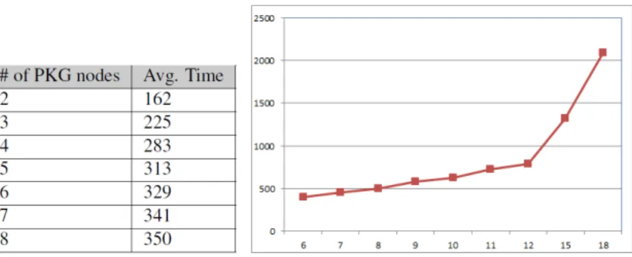
In order to measure the time required for completing the distribution phase with different numbers of PKG nodes, we performed several tests by keeping all other system parameters constant. More specifically, we changed the number of nodes (n) from 6 to 18 while keeping the threshold number (k) and other system parameters constant in order to see how the number of nodes effects the start-up time (time for completing the setup and the distribution steps).
Graph displayed in Figure3.4shows how the time increases exponentially with the number of nodes (n). PKGs exchange n × n messages during setup and distribution steps. Considering that this setup phase needs to be executed only during system establishment or whenever a master key renewal is needed, an average time of 2 seconds is considered acceptable.
3.2.3.2 Extraction
In this test phase we focused on the time required by the client for extracting its pri-vate key. We changed the threshold number (k) from 2 to 8 while keeping the num-ber of nodes (n) and the other system parameters constant. Changing the threshold value, the number of PKG nodes that the client needs to contact for key extrac-tion changes. The value displayed in Figure3.5 indicates the total extraction time together with the network delay and the .
FIGURE3.5: Key extraction phase performance test (Time in ms.)
This test shows that the performance of the key extraction phase mostly depends on the network delay. The time increases logarithmically with the threshold value. In fact the client has to contact k PKG nodes and every signed piece (siH(ID))
retrieval increases the total time. Keeping the threshold value too low will cause the system to be more exposed to an attacker trying to capture the user’s private key, while keeping it too high will slow down the key extraction process. When the threshold value is higher than k = ⌊n/2⌋ + 1 we also sacrifice reliability considering the case that some of the PKG nodes crashes.
By using a (n, k) threshold scheme for secret sharing which is summarized in Sec-tion2.1.4with n = 2k − 1 we get a robust key management scheme. Even if ⌊n/2⌋ = k −1 of the n pieces are destroyed, we still can recover the original key. On the other hand, our opponents cannot reconstruct the key even if they retrieve ⌊n/2⌋ = k − 1 of the remaining k pieces.
According to the practical analysis performed, it can be said that the selection of n between 7 and 14 and k between 4 and 7 (complying with the equation n = 2k − 1) is acceptable and applicable in terms of security, reliability and speed.
100 200 300 400 500 600 0 4 8 12 16 20 24 28 32
FIGURE3.6: Simultaneous answer performance test (Time in ms.)
In most environments, many PLCs and masters can be turned on or connected to the system simultaneously. In order to verify the performance of the DPKG system we performed several test increasing the number of clients that simultaneously com-municate with the DPKG system. Different numbers of clients contact the DPKG system to extract their private keys. The test is performed contacting 8 PKG nodes and number of clients that simultaneously contact to the PKG nodes rages from 2 to 32. The results displayed in Figure3.2.3.2show that there is not an explicit limit to the simultaneous requests. The implicit limits are only due to the computational resources of the machines.
3.2.3.3 Signature & Verification
The goal of this test is to present some preliminary values of a signature imple-mentation between two SCADA entities: master and slave. The communication is performed through the Modbus protocol [23] [19]. In particular, a master signs a Modbus package by using the private key generated in the previous step and sends it to a slave (PLC). The client verifies the data integrity and sender’s identity by following the identity based signature scheme described in Section2.2.
Throughout the testing phase we used type A elliptic curves. This type of curve is described by the equation
(a) Read coils command (b) Write coils command
FIGURE3.7: Time spent for signing and verifying a Modbus package
The curve is defined over the field Fqfor some prime q = 3 mod 4. The order r is
some prime factor of q + 1. Moreover, we used a symmetric pairing where G1and
G2are the set of points E(Fp).
The test is performed in two parts as:
• Master sends a ReadCoilsRequest to slave and waits ReadCoilsResponse; • Master sends a WriteCoilsRequest to slave and waits WriteCoilsResponse.
Tables below show the total time spent (in msec) for signing and verifying Modbus packages according to the length (in bits) of selected security parameters r and q where q + 1 = r ∗ h.
As it is possible to see in Figure3.7(a) and 3.7(b) the total time spent rages from minimum 17 msec to maximum 380 msec. Considering that we used a non-optimized prototype, we can consider that these results are quite promising.
3.2.4
Conclusion for the Case Study
SCADA systems are usually used to control critical infrastructures which makes security of them highly essential. The most important vulnerability of SCADA systems is the lack of authentication mechanism due to the SCADA protocols. In this study after proposing the use of an identity based signature scheme to secure SCADA protocols, we presented a completely distributed scheme for generating identity based private keys for the entities involved in a SCADA system. The ad-vantages of this approach are not negligible. The use of identity based signatures makes the use of certificates and certification authorities unnecessary as well as it
makes the use of centralized repositories for storing public keys also unnecessary. It provides SCADA systems with authenticity efficiently. Moreover, after performing a private key generation the keys can also be used for encryption to provide confi-dentiality if it is needed. The presented distributed architecture provides robustness against ICT attacks and finds its perfect application in those geographically sparse SCADA systems composed of a huge number of active elements. The tests pre-sented show how this approach is applicable for the SCADA environment in terms of security, reliability and time.
Chapter 4
Using Petri Nets for Modeling and
Analyzing Cryptographic Protocols
4.1
Introduction to Petri Nets
The mathematical concept to describe systems with distributed states was developed by Carl Adam Petri in 1962 in his thesis [24]. With his dissertation he laid the basis of Petri net theory.
Petri net is a mathematical and graphical modeling tool useful for modeling con-current, distributed, asynchronous, parallel, nondeterministic, and/or stochastic sys-tems. As a graphical tool, it can be used as a visual-communication aid similar to flow charts, block diagrams and networks. Tokens are used in these nets to simu-late the dynamic and concurrent activities of systems. As a mathematical tool, it is possible to set up state equations, algebraic equations, etc.
The concept of Petri nets is a result of searching methods for describing and ana-lyzing information and control data flow in information processing. The Petri net theory is well suited to describe the dynamic behavior of complex concurrent sys-tems based on graph theoretical concepts.
In this chapter a brief summary of Petri net theory is given with respect to the nota-tion and terminology of [25] and [26].
Definition 4.1. Formally, a net is a bipartite, non-empty, directed graph without isolated nodes and it is represented as;
FIGURE4.1: Demonstration of firing rule: (a) t0is enabled (b) t0is fired
where
• B = b1, b2, . . . bmis a finite set of places,
• E = e1, e2, . . . , enis a finite set of transitions,
• F ⊆ (B × E) ⋃(E × B) ∈ is a set of arcs, • B ∩ E = ∅ and B ∪ E ≠ ∅.
Set B is also considered as the set of atomic (local) states / conditions while set E is the set of atomic (local) transitions/ events. It is important to note that states and transitions are distinct. Global (distributed) state is the case set of conditions hold-ing concurrently while global (distributed) transition is the set of events occurrhold-ing concurrently.
There is also a graphical notation for the elements of Petri nets. State elements are drawn as circles , the transition elements are represented with boxes and the flow relation is shown as edges
If X = B ∪ E and x ∈ X , as usual●x denotes the set {y ∈ X ∣ (y, x) ∈ F}; x● is defined similarly. A net is pure when ∀x ∈ X ●x ∩ x●= ∅. A net is simple when (∀x, y ∈ X )
●x =●yand x●=y●implies x = y. In this study pure and simple nets are used.
A set of conditions c ⊆ B is called a case. An event e ∈ E can occur at a case c when
●e ⊆ cand e●∩c = ∅; we say that e is enabled at case c. When e occurs at c, the case
following c will be c′= (c ∖●e) ∪ e●. When e occurs and transforms case c in c′we say that event e is fired. Cases are graphically represented by black tokens in the conditions belonging to c.
FIGURE4.2: Demonstration of firing rule: (a) t0is not enabled (b) t0cannot fire
Example4.2. Another example shown in Figure 4.2 demonstrates a case that vio-lates firing rule.
In Figure4.2 (a) t0 cannot fire since its preconditions are not held. In other words
p1 must hold a token so that t0 would be enabled. In Figure 4.2 (b) t0 cannot fire
because its postcondition is not empty.
There are many types of Petri Nets including place – transition nets, condition – event nets / elementary nets , colored Petri nets, timed Petri nets and stochastic Petri nets.
In this thesis only the elementary Petri nets are used. In an elementary Petri net system there are conditions, that can either be true or false represented by places and events, that can occur represented by transitions.
In this work elementary Petri nets are used due to the below considerations:
• Elementary nets leave the representation open to the inclusion of low-level signal processing;
• They provide use of basic tools for proving structural properties of the model like invariants analysis at the level of basic signals;
• By using elementary nets one has the properties of interest represented as boolean variables;
• Use of Elementary Petri Nets allows researchers to use powerful model check-ing tools like LOLA [7] [27].
4.2
Modeling with Elementary Petri Nets
In this work we used elementary Petri nets for modeling DPKG for the formal anal-ysis of the protocol. The reasons for choosing elementary nets are stated in previous section.
Definition4.2. An elementary net is a 4-tuple
EN = (B, E, F, m0)
where (B, E, F) is the underlying net of EN denoted by und(N) and m0is the initial
marking (initial case) of EN, inc(EN)
Let EN be an elementary net system and BEN, EEN and FEN denote respectively
the set of conditions in EN, the set of transitions in EN and the set of arcs in EN. Furthermore, MEN= [m0>EN the set of markings (cases) of EN.
While m ∈ MEN and e1, e2∈EEN e1and e2can be related to each other at m in five
ways at least: 1. Sequence:
FIGURE4.3: Sequence of events in a Petri net system
e1 can occur but e2 cannot occur until e1 occurs. e1and e2 are in sequence at m if
and only if m[e1>, ¬(m[e2>), andm′[e2>m′. Sequence of events is demonstrated
in Figure4.3. 2. Conflict (choice):
e1 and e2 can occur individually at m but they cannot occur together at the same
time. e1 and e2 are in conflict at m if and only if m[e1>, m[e2>and¬(m[e1, e2]).
An example of conflict case is displayed in Figure4.4. 3. Concurrency:
FIGURE 4.4: Conflict case in a Petri net system
e1and e2 can occur at m without interfering each other. No order is specified over
the occurrence. e1 and e2can occur at m if and only if m[e1, e2>. Concurrency of
two events e1and e2can be seen in Figure4.5.
FIGURE4.5: Concurrency of two events in a Petri net system
In addition to sequence, conflict and concurrency many other characteristics of a distributed system activities can be modeled by elementary Petri nets such as syn-chronization and mutually exclusion.
In a distributed event system an event may require multiple resources. The resulting synchronization of resources can be captured by transitions of the type shown in Figure 4.6. In the figure, e1 is enabled only when each of p1 and p2 receives a
token. The arrival of a token into each of the two places could be the result of a sequence of events elsewhere in the rest of the Petri net model.
FIGURE4.6: Case of synchronization in a Petri net system
5. Mutually exclusion:
Two processes are mutually exclusive if they cannot be performed at the same time due to constraints on the usage of shared resources. Demonstration of this situation in Petri nets is given in Figure4.7.