Lyotropic Liquid-Crystalline Mesophase of Lithium Tri
flate−Nonionic
Surfactant as Gel Electrolyte for Graphene Optical Modulator
Fadime M. Balci,
†Sinan Balci,
*
,‡Coskun Kocabas,
*
,§and Ömer Dag
*
,† †Department of Chemistry and UNAM, Bilkent University, 06800 Ankara, Turkey‡Department of Astronautical Engineering, University of Turkish Aeronautical Association, 06790 Ankara, Turkey §Department of Physics and UNAM, Bilkent University, 06800 Ankara, Turkey
*
S Supporting InformationABSTRACT: Lithium salt (noncoordinating anions, such as lithium triflate (Ltf)) gel electrolytes may be key for the practical use of electrochemical devices. We introduce a new lyotropic liquid-crystalline (LLC) mesophase using Ltf, a small amount of water (as low as 1.3 water per Ltf), and nonionic surfactant (C18H37(OCH2CH2)10OH, C18E10). The LLC phase forms over a broad range of Ltf/C18E10mole ratios, 2−18. The clear ethanol solution of the ingredients can be either directly spin-coated over a glass substrate to form a gel phase or it can be prepared as a gel by mixing Ltf, water, and C18E10. The mesophase leaches out surfactant molecules at low salt concentrations, but at a salt/surfactant mole ratio of above 8, the phase is homogeneous with a cubic mesostructure, fully transparent in the visible optical region, mechanically flexible, and an effective gel electrolyte. We have observed a large electrostatic doping on graphene with the Fermi energy level of∼1.0 eV using Ltf-C18E10
gel electrolytes. The Ltf-based gels demonstrate better properties than commonly used ionic liquid electrolyte in graphene optical modulators. The stability of the new gel electrolytes and their superior performance make them suitable electrolytes for use in graphene-based optical modulators.
■
INTRODUCTIONLyotropic liquid-crystalline (LLC) mesophases consist of at least two components, such as a solvent and a surfactant. The solvent may be water,1,2 water−oil,3 aqueous solutions,4 ionic liquids,5−7acids,8,9and salts.10−12The salts can be alkali metals (LiX, X is NO3−, Cl−, Br−, I−),11,12alkaline earth metals (CaX2, X−is Cl−and NO3−),12transition metals ([M(H2O)n](NO3)2, where M represents Mn(II), Co(II), Ni(II), Zn(II), and Cd(II)),10or lanthanides (Eu(II) and La(III)).13The common properties of these salts are their low melting point or high solubility.11,12 It is also important to note that the melting points of the salts drop10and their solubility is enhanced11,12in confined spaces, such as in the hydrophilic domains of the mesophases, known as soft confinement effect.14Even though most lithium salts have a high melting point, because of their high solubility, they form LLC phases with nonionic surfactants.11,12
The salt−surfactant LLC mesophases are important in the development of gel-electrolytes for practical electrochemical devices,15such as solar cells,16batteries,17supercapacitors,8and so on. Therefore, it is important to investigate the salt− surfactant mesophases, especially the lithium salt−surfactant mesophases, toward the development of gel-electrolytes for electrochemical systems. Moreover, the lithium salts of noncoordinating anions (such as BF4−, PF6−, and CF3SO3−) are very important due to their high ionic conductivity.18−20 However, the supersaturated solutions of lithium salts of these
ions have not been investigated as a solvent in the salt− surfactant LLC mesophases. For instance, LiCF3SO3is a very soluble salt in water and can be a good candidate for a stable LLC mesophase, which may be used as the gel-electrolyte in various super capacitors and battery systems.
For example, a phosphoric acid−surfactant mesophase, used as a gel-electrolyte, has been recently tested in a graphene optical modulator, a supercapacitor consisting of two graphene electrodes and a gel-electrolyte, with excellent results.8 Polarizing the electrolyte by an applied electricfield between the two graphene electrodes effectively dopes the graphene and significantly shifts its Fermi level to effectively modulate the optical transmittance of graphene.8,21 Major challenges in the device configuration include finding an electrolyte that (i) has a large electrochemical window, (ii) shifts the Fermi level of graphene greater than 1 eV for visible optoelectronic applications, (iii) reaches very large charge densities on graphene, (iv) is transparent in the visible region, and (v) is mechanically flexible for solid state device applications. For these reasons, ionic liquids have been considered target materials.21 However, gel-electrolytes that perform as well as ionic liquids may be more beneficial for use in practical applications.
Received: April 18, 2017
Revised: May 11, 2017
Published: May 12, 2017
than 3 months as measured in this study), and so on.
■
EXPERIMENTAL PARTPreparation of Ltf-C18E10 Solutions. In a typical preparation, the required amount of Ltf wasfirst dissolved in ethanol, and following that the required amount of C18E10was added and stirred overnight at RT to obtain a clear solution. For example, the sample with 2Ltf/C18E10 was prepared as follows. First, 2 mmol (312 mg) of Ltf was dissolved in 5 g EtOH. Subsequently, 1 mmol (711 mg) of C18E10was added to the above solution and stirred overnight to obtain a homogenized solution. The clear solutions were then coated on glass slides via spin coating at 1000 rpm for 15 s to obtain LLC mesophases.
Preparation of Ltf-C18E10 LLC Mesophases. The required amounts of Ltf, water, and C18E10 were placed in a vial and sealed using Teflon tape. As an example, the sample with 4Ltf/C18E10 and 3H2O/Ltf was prepared by mixing 4 mmol (624 mg) of Ltf, 1 mmol (711 mg) of C18E10, and 12 mmol (216 mg) of H2O in a vial. The vial was kept at 80°C in a water bath for 24 h to obtain homogenized gels.
Synthesis of Graphene. Graphene layers on ultrasmooth copper foil substrates (Mitsui Mining and Smelting Company, B1-SBS) were synthesized using chemical vapor deposition (CVD), as described in our previous publications.8,21We are able to synthesize single and multilayer graphene in a large area (several cm2). During the annealing step, the copper oxide on the copper substrate was removed by sending H2 gas with a flow rate of 100 sccm. The graphene layer on the copper substrate was synthesized at 1035°C and 5 Torr under a CH4 flow rate of 10 sccm. After 30 s of growth, the growth was stopped and cooled to room temperature.
AC Conductivity Measurements. AC conductivity measurements were taken using a Gamry G750 potentiostat/ galvanostat operating at an AC voltage of 10 mV and 100 kHz. The FTO glass electrodes were prepared as described in our previous publications.16The cell constant was determined using standard KCl solutions with a known conductivity, each time before the measurement of the gels. The solutions were dropped over the prestretched line over FTO glass. Upon evaporation of the solvent (∼24 h), the counter and reference electrodes were attached to one side and working electrode was attached to the other side for the conductivity measurements.
XRD Measurements. Small-angle XRD patterns were collected using Miniflex diffractometer, equipped with
high-power Cu Kα source operating at 30 kV/15 mA and
wavelength of 1.5405 Å. Film samples that were spin-coated over glass slides were used for the XRD measurements.
1813 photoresist liquid and then annealed at 60°C overnight. To transfer the graphene from photoresist layer to a glass surface, the copper film attached to the graphene was chemically etched in 1 M FeCl3 aqueous solution and then washed with excessive amount of water. Subsequently, the graphene layers attached to the photoresist were placed on a glass surface and heated to 80°C for a few minutes on a hot plate. Following this the photoresist layer was removed with acetone and washed with an ample amount of isopropanol. Another glass substrate with a ∼100 nm gold film and graphene-covered glass substrate were then joined. The counter electrodes were separated by a 100μm thick plastic spacer, a double-sided adhesive tape stripe. The space between the graphene and gold electrodes wasfilled with an electrolyte. The ionic liquid electrolyte used in this study is diethylmethyl(2-methoxyethyl) ammonium bis(trifluoromethylsulfonyl)imide. Under the applied bias voltage, the electrolyte generates electrical double layer (EDL) at the interface between graphene and electrolyte. The optical properties (transmission) of single-layer graphene were measured in the visible and near-infrared wavelength as a function of the applied bias voltage using a Fourier transform infrared spectrometer (Bruker VERTEX 70v). Lithium-salt-based LLC gel electrolytes were inserted into the graphene supercapacitor by heating the device and electrolyte to 70 °C. ∼20 μL of the synthesized electrolyte was placed at the edge of the device; then, the electrolyteflows in the narrow space between the electrodes due to the capillary forces; see Figure S1 for the details. Capacitance and total resistance of the graphene capacitor were measured by using LCR Meter (Hewlett-Packard, 4284A). Bias voltages to graphene and gold electrodes were applied by using a Source Meter (Keithley, 2400).
■
RESULTS AND DISCUSSIONThe LLC mesophases of lithium triflate (LiCF3SO3, Ltf) and brij 76 (C18H37(OCH2CH2)10OH, C18E10) form over a broad range of salt/surfactant mole ratios (2−18, denoted as #-Ltf-C18E10, where# represents Ltf/C18E10mole ratio), correspond-ing to a ratio as high as 82% (w/w). This indicates that a major component of the mesophase could be the salt species. The mesophases can be prepared as a solution in excess ethanol, which can be completely evaporated upon spin coating over any substrate to obtain the gel LLC phase or prepared as a gel starting from salt, surfactant, and small amount of water. In general, when using the second method, it is more difficult to produce a homogeneous mixture of the LLC phase; however, it is more practical to use as a gel electrolyte in electrochemical applications.
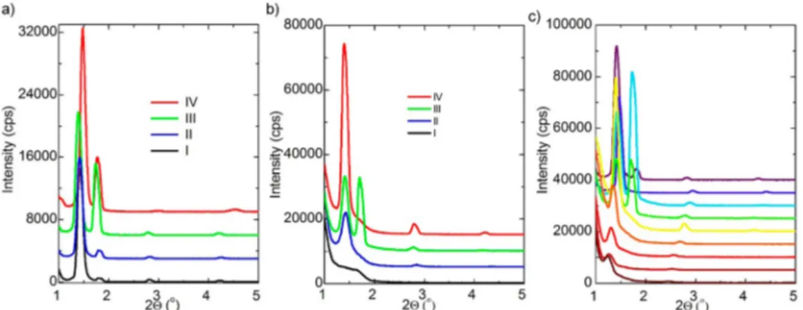
Both mesophases, prepared as gels and solutions, were characterized using POM, XRD, and FTIR techniques to elucidate the structural details as well as AC conductivity measurements for the electrical characterization.Figure 1shows a series of small-angle XRD patterns of samples with different concentration of Ltf. Notice that bothfilms, prepared by spin coating or spreading over a substrate, diffract at small angles with no diffraction at high angles. In fact, both preparation methods provide the same LLC phase upon aging.
The samples, prepared using ethanol solution, have been monitored by recording their XRD patterns over 5 weeks to ensure homogeneous LLC phase through complete ethanol evaporation. Figure 1a,b shows the aging process of two
samples, namely, 2 and 8 Ltf and 1 C18E10. The diffraction lines observed immediately after spin coating undergo some changes, while keeping the line position relatively constant. At low Ltf concentrations, there are two sets of diffraction lines at small angles, which eventually become a single set at higher concentrations; seeFigure 1. The small-angle XRD pattern of 2-Lt-C18E10 displays lines at 1.48, 1.77, 2.99, and 4.54°, 2θ values. The diffraction line at 1.77° likely corresponds to a free surfactant, which gradually disappears at higher Ltf concen-trations. The free surfactant line appears upon coating a clear solution of the salt-surfactant, gradually increases after 1 h, and then gradually decreases over time with further aging the gel films. It is likely that the mesophase leaches out crystalline
Figure 1.XRD pattern of (a) 2-Ltf-C18E10with aging (I) fresh, (II) 1 day, (III) 1 week, and (IV) 2 weeks. (b) 8-Ltf-C18E10mole ratio with aging (I) fresh, (II) 1 day, (III) 1 week, and (IV) 5 weeks. (c)#-Ltf-C18E10with increasing# from 2 (top) to 18 (bottom) with an increment of 2.
Figure 2. Normalized ATR-FTIR spectra of (a,b) #-Ltf-C18E10 with increasing Ltf (Ltf/C18E10 mole ratio increases from 2 to 18 with four increments, bottom is the spectrum of pure C18E10). ATR-FTIR spectra of xLtf/C18E10during aging: x is (c) 2, (d) 10, and (e) 18 (fresh and 4 h). (f) Normalized spectra after 24 h of aging of the same samples.
concentrations but is metastable and undergoes phase separation into salt-rich LLC and salt-free surfactant domains over time. Therefore, the salt concentration in the LLC domains is much higher than 2Ltf/C18E10. The free surfactant line gradually disappears with an increasing Ltf/C18E10 mole ratio in the samples, and at a mole ratio above 8Ltf/C18E10, all diffraction lines can be indexed to a cubic mesophase. Also, this behavior correlates with the POM images that appear dark between the two crossed polarizers. Note that the diffraction lines gradually shift to lower angles with an increasing Ltf/ C18E10 mole ratio. If we consider the line at ∼1.34°, 2θ, originating from the (200) plane of the cubic phase, the unit -cell parameter increases from 120 to 142 Å by increasing Ltf/ C18E10 mole ratio from 2 to 18, respectively; see Figure 1c. However, the changes of the unit-cell parameters, at low Ltf/ C18E10ratio, are negligibly small and gradual at higher ratios. It is likely that the Ltf/C18E10 ratio in the LLC mesophase is constant to a mole ratio around 8 and then gradually increases at higher salt concentrations, where the extra surfactant molecules in the low Ltf concentrations are leached out from the media to compensate for a constant salt/surfactant ratio.
Furthermore, the salt−surfactant mixtures display meso-phases in the following order V1(bicontinuous cubic), H1(normal hexagonal), and I1 (micellar cubic), with a dominating hexagonal phase, with an increasing salt/surfactant mole ratio. Therefore, it is reasonable to conclude that the hexagonal phase of the Ltf-C18E10 system is metastable and undergoes a phase separation into micellar cubic phase and free surfactant at low Ltf/C18E10mole ratios. Besides, the diffraction patterns in Figure 1c show some variations during the aging process; however, all diffraction lines are indexed to a micellar cubic phase, where the lines at 1.39, 1.70, 2.77, and 4.16°, 2θ, correspond to (200), (211), (400), and (600) planes, respectively. The line, corresponding to the (200) plane, remains in all of the samples but gradually loses its intensity and shifts to smaller angles due to increase in unit-cell size in the mesophase to accommodate the excess salt species. Interest-ingly, the mesophase in the Lft-C18E10 is cubic in all compositions, which is quite unusual for salt surfactant mesophases.
In addition, we recorded the ATR-FTIR spectra of a series of samples during solvent evaporation with different Ltf/C18E10 mole ratios.Figure 2a,b shows a series of spectra after aging the samples for 24 h, where the mesophase no longer undergoes changes. The peaks due to the Ltf species increase with an increasing salt concentration in the media. However, it is difficult to spectroscopically quantify the free surfactant in the media because the spectrum of the surfactant changes to the final spectrum upon the addition of as little as 0.1 salt/
two components at∼1272 and ∼1300 cm , originate from the asymmetric stretching mode of the SO3unit of the free and coordinated triflate ion, respectively.23,24
Figure 2c−f shows the surfactant νCH stretching and water-bending and -stretching regions of three samples in two different stages of the aging process. The fresh samples display weak water bending at ∼1649 cm−1 and a broad water-stretching feature at 3440 cm−1with a shoulder around 3200 cm−1, characteristic of the bulk water (hydrogen-bonded network of water). TheνCH stretching region displays peaks related to the surfactant molecules and ethanol. However, upon complete evaporation of ethanol, both the bending and stretching modes of the water display drastic changes; compare the spectra in Figure 2c−e. The bending mode gradually red shifts and becomes more intense and sharper, while stretching modes are blue-shifting, from 1649 to 1635 cm−1and 3440 to 3510 cm−1, respectively, indicating that the water is becoming free or hydration-only water;25compare the spectra inFigure 2f. The bending mode also becomes sharper with an increasing Ltf in the media. The stretching to bending intensity ratio also displays drastic changes, from 2.5 to 1.0 increasing from 2 to 18Ltf/C18E10 mole ratio, likely indicating the change in the bulk/hydration water ratio in the media. To support this observation and also to determine the water content of the samples, we monitored the weight change over a four-digit balance during ethanol evaporation of the solutions. Owing to the very fast evaporation of ethanol, the mass of the solution decays exponentially; seeFigure 3a. After mesophase formation, the mass of the solution becomes constant. Indeed, the LLC mesophase stabilizes at around 2H2O/Ltf for both 2-Ltf-C18E10
Figure 3.Variation of (a) the mass and (b) the conductivity of the samples with a Ltf/C18E10mole ratio of between 2 and 18.
and 4-Ltf-C18E10 and at around 1.3H2O/Ltf for both 8-Ltf-C18E10 and 18-Ltf-C18E10.
Remarkably, the water/Ltf mole ratio decreases to almost 1.3 around 8 Lft/C18E10 and remains constant above a mole ratio of 8. These observations are consistent with the behaviors observed in the XRD patterns as well as the discussions in the
XRD Measurements section. Therefore, it is reasonable to conclude that the Ltf-C18E10 system is metastable up to an 8 Ltf/C18E10 mole ratio and leaches out surfactant with some bulk-like water.
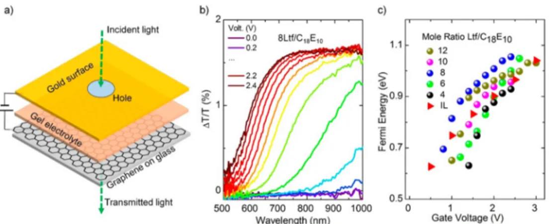
Additionally, we recorded the AC conductivity of a set of #-Lft-C18E10 during aging using an FTO substrate that was designed for this purpose.16 The AC ionic conductivity increases slowly in samples with a low Lft concentration and increases gradually after a mole ratio of 6; see Figure 3b. Notably, the Ltf-C18E10 mesophase displays the highest AC ionic conductivity among all lithium salt−surfactant systems investigated in the literature.12,22The highest conductivity was reported for the 18-Lft-C18E10 to be 2.6 mS/cm. Notice that there is a factor of 3 compared with the polyelectrolytes of Lft using poly(ethylene oxide)s.26−28There, the Lft has a limited solubility and also a stronger ion−ethylene oxide interaction that likely reduces the mobility of lithium ion in the media. However, in the lithium salt−surfactant systems, the salt is in the molten phase in the presence of a small amount of water with better ionic conductivity. It is likely that the lithium ion mobility is also enhanced in the confined space due to thermodynamic effects that need to be further investigated.29,30 We employed the Ltf-C18E10 LLC mesophase as a gel electrolyte in a graphene optical modulator to evaluate the electro-optical performance of the LLC gels. For this purpose, five compositions were chosen with an Ltf/C18E10mole ratio of 4, 6, 8, 10, and 12. Figure 4a displays the schematic representation of the graphene-based supercapacitor structure used as an optical modulator. A goldfilm on a glass surface and graphene layer on an another glass surface form the capacitor structure (Figure S1). The electrodes are separated by an insulating spacer layer. The gel electrolyte was placed between the capacitor plates by heating to a temperature higher than gel electrolyte’s melting point (∼75 °C) and then placing the liquid electrolyte on preheated graphene capacitor device; seeFigure S1. It should be noted that the graphene−gold supercapacitor works by ion gating. Owing to the electric double-layer (EDL)
formation, the electric field is screened very close to the graphene surface (only a few nanometers) by the mobile ions in the medium. The fractional variation of the transmission of the incident light through the device as a function of the applied gate voltages is shown inFigure 4b andFigure S2. It should be noted that the ideal suspended graphene in air absorbs onlyΠα = 2.3% (α is the fine structure constant) of the incident light.31 When graphene is placed on a substrate such as a glass substrate in our case, the graphene absorbs 1.45% (corrected absorption =Πα(2/(1 + n)),2where n is the refractive index of BK7 glass at 600 nm, 1.5163) of the incident light,32which is in close agreement with our observed variation (∼1.6%) inFigure 4b. This value should decrease with increasing the defect density on graphene. Because of the Pauli blocking, the graphene becomes transparent for incoming light at energies smaller than twice the Fermi level shift.33Note that the Pauli blocking happens when the final optical transition states are occupied because of the increase in the charge density on graphene. The observed Fermi level shift increases linearly with the applied gate voltages. The mole ratio of the Ltf/C18E10gel electrolyte used inFigure 4b is 8. Also, a series of samples with varying composition of Ltf/C18E10 mole ratio were prepared and their electro-optical performances have been tested (Figure 4c). Remarkably, we observed that the Ltf/C18E10mole ratio of 8 has the best performance in the graphene optical modulators. In addition, the fabricated device showed a similar performance after 3 months; seeFigure S6. The capacitance and resistance of all compositions have been measured (see the Supporting Information, Figures S2−S6). In addition to the Ltf salt, we also prepared and used LiCl, LiBr, and LiNO3 salt-based LLC mesophases as electrolytes in graphene supercapacitors. However, we were only able to insert an LiCl-based electrolyte (due to high melting points of those mesophases) into the device, which performed very weakly when compared with the Ltf-based gel electrolytes; see Figure S2f. Figure 4c demonstrates the optical performance of all Ltf/C18E10 compositions and a commonly used ionic liquid in graphene supercapacitors; seeFigure S7as well. We observed that an Ltf/ C18E10 mole ratio of 8 displays the best performance in graphene optical modulators.
Figure 4. Application of Ltf based LLCs gel electrolytes for graphene optical modulators. (a) Schematic representation of a graphene-gold supercapacitorfilled with Ltf salt-based liquid-crystalline gel electrolyte. The LLC system has Ltf/C18E10mole ratio of 8. (b) Variation of normalized transmission of the graphene supercapacitorfilled with Ltf salt-based liquid-crystalline gel electrolyte versus the wavelength of the incident light for various applied bias voltages. (c) Variation of Fermi energy level of graphene as a function of applied bias voltages for varying Ltf/C18E10mole ratio in LLC gel electrolytes and typical ionic liquid used in graphene optical modulators.
18 10
electrolyte displays good ionic conductivity and an excellent electro-optical performance in the graphene-based optical modulators. Maximum Fermi energy shift in graphene is observed in the 8Ltf/C18E10. The LLC gel electrolyte has many advantages in terms of device fabrication, electrolyte leakage, electrochemical properties, etc. The results pave the way for the development of gel electrolytes, which can increase the Fermi energy level shift of graphene to allow for the realization of graphene-based optoelectronics in the visible region of the electromagnetic spectrum.
■
ASSOCIATED CONTENT*
S Supporting InformationThe Supporting Information is available free of charge on the
ACS Publications websiteat DOI:10.1021/acs.jpcc.7b03622. Schematic representation and photographs of the electrodes. More electrical and optical characterization data of the electrodes with gel electrolytes and ionic liquid. (PDF)
■
AUTHOR INFORMATIONCorresponding Authors
*S.B.: E-mail:[email protected].
*C.K.: E-mail:[email protected]. *O.D.: E-mail:[email protected].
ORCID
Coskun Kocabas: 0000-0003-0831-5552 Ömer Dag:0000-0002-1129-3246
Notes
The authors declare no competingfinancial interest.
■
ACKNOWLEDGMENTSWe thank the Scientific and Technological Research Council of Turkey (TÜBİTAK) under project numbers 13F278 and 215Z193 for the financial support and Dr. Osman Balci (Bilkent University) for his fruitful discussions. O.D. is a member of the Science Academy, Istanbul, Turkey.
■
REFERENCES(1) Mitchell, D. J.; Tiddy, G. J. T.; Waring, L.; Bostock, T.; Mcdonald, M. P. Phase-Behavior of Polyoxyethylene Surfactants with Water-Mesophase Structures and Partial Miscibility (Cloud Points). J. Chem. Soc., Faraday Trans. 1 1983, 79, 975−1000.
(2) Dong, R. H.; Hao, J. C. Complex Fluids of Poly(oxyethylene) Monoalkyl Ether Nonionic Surfactants. Chem. Rev. 2010, 110, 4978− 5022.
(3) Alexandridis, P.; Olsson, U.; Lindman, B. A Record Nine Different Phases (Four Cubic, Two Hexagonal, and One Lamellar
(7) Greaves, T. L.; Drummond, C. J. Ionic Liquids as Amphiphile Self-assembly Media. Chem. Soc. Rev. 2008, 37, 1709−1726.
(8) Tunkara, E.; Albayrak, C.; Polat, E. O.; Kocabas, C.; Dag, Ö. Highly Proton Conductive Phosphoric Acid-Nonionic Surfactant Lyotropic Liquid Crystalline Mesophases and Application in Graphene Optical Modulators. ACS Nano 2014, 8, 11007−11012.
(9) Olutaş, E. B.; Balcı, F. M.; Dag, Ö. Strong Acid-Nonionic Surfactant Lyotropic Liquid-Crystalline Mesophases as Media for the Synthesis of Carbon Quantum Dots and Highly Proton Conducting Mesostructured Silica Thin Films and Monoliths. Langmuir 2015, 31, 10265−10271.
(10) Çelik, Ö.; Dag, Ö. A New Lyotropic Liquid Crystalline System: Oligo(ethylene Oxide) Surfactants with [M(H2O)nXm Transition Metal Complexes. Angew. Chem., Int. Ed. 2001, 40, 3800−3803.
(11) Albayrak, C.; Cihaner, A.; Dag, Ö. A New, Highly Conductive, Lithium Salt/Nonionic Surfactant, Lyotropic Liquid-Crystalline Mesophase and Its Application. Chem. - Eur. J. 2012, 18, 4190−4194. (12) Albayrak, C.; Barım, G.; Dag, Ö. Effect of Hygroscopicity of the Metal Salt on the Formation and Air Stability of Lyotropic Liquid Crystalline Mesophases in Hydrated Salt-surfactant Systems. J. Colloid Interface Sci. 2014, 433, 26−33.
(13) Zakharova, L. Y.; Ibragimova, A. R.; Valeeva, F. G.; Kudryavtseva, L. A.; Konovalov, A. I.; Zakharov, A. V.; Selivanova, N. M.; Osipova, V. V.; Strelkov, M. V.; Galyametdinov, Y. G. Self-organization and Catalytic Activity of the Poly(ethylene Glycol)(10) Monododecyl ether/poly(ethyleneimine)/lanthanum Nitrate System. J. Phys. Chem. C 2007, 111, 13839−13845.
(14) Wang, L. M.; He, F.; Richert, R. Intramicellar Glass Transition and Liquid Dynamics in Soft Confinement. Phys. Rev. Lett. 2004, 92, 095701−4.
(15) Kato, T.; Yoshio, M.; Ichikawa, T.; Soberats, B.; Ohno, H.; Funahashi, M. Transport of Ions and Electrons in Nanostructured Liquid Crystals. Nat. Rev. Mater. 2017, 2, 17001.
(16) Yılmaz, E.; Olutaş, E. B.; Barım, G.; Bandara, J.; Dag, Ö. Lithium Salt-Nonionic Surfactant Lyotropic Liquid Crystalline Gel-Electrolytes with Redox Couple for Dye Sensitized Solar Cells. RSC Adv. 2016, 6, 97430−97437.
(17) Song, J. Y.; Wang, Y. Y.; Wan, C. C. Review of Gel-type Polymer Electrolytes for Lithium-ion Batteries. J. Power Sources 1999, 77, 183− 197.
(18) Tarascon, J. M.; Armand, M. Issues and Challenges Facing Rechargeable Lithium Batteries. Nature 2001, 414, 359−367.
(19) Rosol, Z. P.; German, N. J.; Gross, S. M. Solubility, Ionic Conductivity and Viscosity of Lithium Salts in Room Temperature Ionic Liquids. Green Chem. 2009, 11, 1453−1457.
(20) Croce, F.; Appetecchi, G. B.; Persi, L.; Scrosati, B. Nano-composite Polymer Electrolytes for Lithium Batteries. Nature 1998, 394, 456−458.
(21) Polat, E. O.; Kocabas, C. Broadband Optical Modulators Based on Graphene Supercapacitors. Nano Lett. 2013, 13, 5851−5857.
(22) Barım, G.; Albayrak, C.; Yılmaz, E.; Dag, Ö. Highly Conducting Lyotropic Liquid Crystalline Mesophases of Pluronics (P65, P85, P103, and P123) and Hydrated Lithium Salts (LiCl and LiNO3). Langmuir 2014, 30, 6938−6945.
(23) Ferry, A.; Jacobsson, P.; Stevens, J. R. Studies of Ionic Interactions in Poly(propylene Glycol)4000 Complexed with Triflate Salts. J. Phys. Chem. 1996, 100, 12574−12582.
(24) Frech, R.; Chintapalli, S.; Bruce, P. G.; Vincent, C. A. Crystalline and Amorphous Phases in the Poly(ethylene Oxide)-LiCF3SO3 System. Macromolecules 1999, 32, 808−813.
(25) Cammarata, L.; Kazarian, S. G.; Salter, P. A.; Welton, T. Molecular States of Water in Room Temperature Ionic Liquids. Phys. Chem. Chem. Phys. 2001, 3, 5192−5200.
(26) Lightfoot, P.; Mehta, M. A.; Bruce, P. G. Crystal-Structure of the Polymer Electrolyte Poly(Ethylene Oxide)3LiCF3SO3. Science 1993, 262, 883−885.
(27) Volel, M.; Armand, M.; Gorecki, W. Influence of Sample History on the Morphology and Transport Properties of PEO-Lithium Salt Complexes. Macromolecules 2004, 37, 8373−8380.
(28) Zardalidis, G.; Ioannou, E.; Pispas, S.; Floudas, G. Relating Structure, Viscoelasticity, and Local Mobility to Conductivity in PEO/ LiTf Electrolytes. Macromolecules 2013, 46, 2705−2714.
(29) Kerr, R. L.; Miller, S. A.; Shoemaker, R. K.; Elliott, B. J.; Gin, D. L. New Type of Li Ion Conductor with 3D Interconnected Nanopores via Polymerization of a Liquid Organic Electrolyte-Filled Lyotropic Liquid-Crystal Assembly. J. Am. Chem. Soc. 2009, 131, 15972−15973. (30) Lee, J. H.; Han, K. S.; Lee, J. S.; Lee, A. S.; Park, S. K.; Hong, S. Y.; Lee, J. C.; Mueller, K. T.; Hong, S. M.; Koo, C. M. Facilitated Ion Transport in Smectic Ordered Ionic Liquid Crystals. Adv. Mater. 2016, 28, 9301−9307.
(31) Nair, R. R.; Blake, P.; Grigorenko, A. N.; Novoselov, K. S.; Booth, T. J.; Stauber, T.; Peres, N. M. R.; Geim, A. K. Fine structure constant defines visual transparency of graphene. Science 2008, 320, 1308−1308.
(32) Fang, H.; Bechtel, H. A.; Plis, E.; Martin, M. C.; Krishna, S.; Yablonovitch, E.; Javey, A. Quantum of Optical Absorption in Two-Dimensional Semiconductors. Proc. Natl. Acad. Sci. U. S. A. 2013, 110, 11688−11691.
(33) Wang, F.; Zhang, Y. B.; Tian, C. S.; Girit, C.; Zettl, A.; Crommie, M.; Shen, Y. R. Gate-Variable Optical Transitions in Graphene. Science 2008, 320, 206−209.