A
NEW
APPROACH TO TIME-FREQUENCY LOCALIZED SIGNAL DESIGN
Ahmet Kemal Ozdemir, Zafer Aydm and Orhan Ankan
Department of Electrical
and
Electronics Engineering,
Bilkent University,
Ankara, TR-06533
TURKEY.
Phone:
90-312-2664307,
Fax:
90-312-2664192
e-mail:
{kozdemir.aydinz.oarikan}@ee.bilkent.edu.tr
ABSTRACT
A novel approach is presented for the design of signals in Wigner
Domain. In this method, the desired signal features in the time frequency domain are specified in two stages. First the user speci fies the spine curve around which the energy of the desired signal is distributed in the time-frequency plane. Then, the user specifics the spread of the desired signal energy around the spine. In addi tion to this fundamentally new way of defining the time-frequency features of the desired signal, the actual synthesis of the signal is perfonned in a warped fractional Fourier transfonn approach [I]. After obtaining the designed signal, it is transformed back to the original time domain providing the final result of the new signal synthesis technique. In contrast to the conventional algorithms, the proposed method provides very good results even if the iMer cross-term structure
of
the desired signal is not specified1. INTRODUCTION AND REVIEW OF THE EXISTING APPROACHES
Time-frequency domain based signal design refers to synthesis
of
a signal from its time-frequency (t-t) distribution which is con structed by the designer to describe the desired localization of the signal energy as a joint function of time and frequency. In many fields people utilize
from
time-frequency domain based signal de sign and synthesis techniques with the purpose of filtering[2, 3],
component extraction[4]
and noise reduction[5]!n
the t-f plane.Design of signals in Wigner domain received considerable in terest throughout the study
of
time-frequency domain based signal synthesis. In the classical WD-based signal designapproach the
user specifies a model
WD
WM (t,
I),
which describes the desired distribution of signal
energy
in the time-frequency plane and then finds a signalZWD(t)
whose WD resembles the model WD. Since, in general, modelWD
is not a valid WD, the desired signalZWD(t)
is obtained by synthesizing a signal whose WD best fitsthe model WD in the least squares sense
ZWD(t)=argm:n IIIW.M(t,f)-W,,(t,fWdtdf ,
(I)
where'theWD
W)(t,
f) of
the signalX(t)
is defined by[5]
W,,(t, f) = I X(t
+t' /2)X"(t - t' /2)e-;2Tr/t' dt'.
(2)
This method provides acceptable results when the auto-term of the desired signal has a linear time-frequency support, which corre sponds to no or negligible cross-term interference
[5].
Howeverif the model WD has a curved time-frequency support and the de sired signal is expected to have significant cross-term interference, then the overall performance of this method is adversely affected To illustrate this phenomenon, in Fig. I(a), a model WD is shown to describe the auto-term structure of a desired signa\. If it were possible to accurately model cross-terms, i.e., inner-interference
terms
[6]
associated with this modelWD
, the designer wouldrun
the synthesis algorithm on thefull WD model given in Fig. I(b) which captures
both
the auto and cross-terms of the desired sig nal. However, because of difficulty of modeling the cross-terms, in practice the desired signal is synthesized from just the auto-term modelWD
given in Fig. l(a). The WD of the synthesized signalZW D (t)
obtained by this way is given in Fig. I(c), where the same color encoding is used in all plots in this figure. As expected, in this example, the auto-term of the designed signal deviates from the model WD given in Fig. I(a), especially at the middle portion where the auto-term has a large curvature.Because of the high sensitivity of the classical WD-based sig nal design algorithm to inaccurate modeling
of the
cross-terms, amasked
WD
(MWD)
based
signal design algorithm has been developed [7].
In this approach, the fit errorbetween the modeled
and the designed WDs is minimized only at those regions of the time-frequency plane which do not contain any cross-term inter
ference.
Assuming that all the troublesomeinterference
terms lie in thedon
'Icare region
1) of the time-frequency plane, the desired signal is synthesized by)ZMWD(t)
=argm�n II IW.M(t,f)-W)(t,f)12dtdl (3)
(t,J)�1)where
ZMWD(t)
is the designed signal. In[7],
a quasi-power al gorithm is given to solve(3)
iteratively. However, no convergence proof for this iterative procedure is given so far.The MWD-based signal design algorithm usually provides bet
ter results
than
the classical WD-based signal design algorithm. As an illustration, the results of the classicalWD
and MWD-basedsignal design algorithms on the model of Fig. I (a) are given in Fig.
I
(c)-(d), respectively. In these plots, it is apparent that the auto-term of the designed signal by the latter algorithm providesa
better fit to the model WD given in Fig. I(a). However, the perfor mance
of
the MWD-based signal design algorithmdegrades
if the support of the expected inner interferenceterms
overlap with the time-frequency support of thedesired
signal as shown in Fig. 2(a). In this case, there is no clear choice for the don't care region. If) When the extent of the don'l care region is relatively large, an
energy
penalty
factor is incorporated into (3) to prevenl the appearance of spurious terms in the synthesized signal [7].these regions
are
not included in
'D,the performance of the MWD
based iterative design method would be close
to
the perfo
rman
ce
of the classical WD-based synthesis algorithm, which is' not go
ing to
be
satisfactory. On the other hand, if they
are
included
in
'D,this algorithm may fail
to
synthesize those portions of the
model
WD
.This can be observed in Fig.
2(b),
where the WD of
the designed signal XMWD{t) is plotted
after
convergence of the
quasi-power algorithm about in
100
iterations. Furthermore, for
complicated inner interference
structure, determining the extent
of
the
don't
care
region can
be very
difficult and tedious. In addition
to the difficulty
i
n
choosing the
right
mask,
'the complexity of
the
MWD-based synthesis algorithm· is considerably higher because
of
its
i
te
rati
v
e computational procedure [7].
2. A NOVEL WIGNER DISTRIBUTION BASED DESIGN MEmOD USING FRACJ'IONAL DOMAIN WARPING
In this paper we propose a novel and highly
efficient
time-frequency
domain based signal design algorithm to alleviate the shortcom
ings of the conventional
signal
design methods when complicated
interference
terms
are
expected in
the
WD
of the ,desired signal.
The new algorithm is based on a recently developed warped frac
tional Fourier transformation (FrFT) algorithm
[i], w
hi
c
h
can
be
used to map signals with, complicated inner interference terms as
shown in Fig. 3{a) into signals with approximately linear time
frequency
supports as
shown in Fig. 3{ d). In the proposed method,
the desired signal
is synthesized in
the warped FrFT
domain, where
its WD has considerably
less interference
terms
.After synthesis
of the signal in the transform domain, it is mapped back
into
time
domain providing the
result of the propose4 algorithm. Since
in
the
new method,
the synthesis is performed in the warped
FrFT
domain, there should be an
easy
way of characterizing the desired
signal
features
in the transform domain instead of the original
time
domain. Furtheimore, the mappings between the time and the
warped FrFT domains
should
beefficient To this
purpose, the
relation
between the
time
and the
transform doniains should
bei
nve
s
tiga
t
ed in depth in the signal design context.
2.1. Fractional Domain Warping
The fractional domain warping concept
was
first introduced in
[I]
to provide high resolution time-frequency representation for sig
nals
with non-linear time-frequency supports. It
is
the general
ization
of the time-domain
warping
to fractional domains. The
warped fractional Fourier transform (FrFT) of a signal
z( t)
is com
puted
by
replacing the
time-dependence
of its FrFT
wi
th
a
warpin
l
function
(t).
Thus,if
x{t)
is
the time
domain si
gnal with the
aorder FrFT
Xa(t),
a ER,
and
(t)
is the warping function, then
the
warped
FrFT
oftJie
signal is
given
by xa
,d
t)
=xa('(t».
The
FrFT
ofthe signal
x{t)
u
se
d in this definition is computed
by
Za(t)
=={P
zHt) �
/
Ka(t, t')z(t') dt'
,(4)
where
the kernel
of the
transformation
Ka(t,t')
is given
in [8].
The FrFT
hasa number of interesting properties
[8].
In this paper,
we make use of
its
rotation
property
which
states
that, the WD
of the
alborder
FrFT of
a
signal is
thesame
as
the
WD
of the
original signal rotated by
an angle
of
a1l'/2
radians in the
clock
wise dire
cti
on[8]
asillustrated in Fig. 3{a)-(b) for
a =-0.8.
In order to establish the mathematic;al details of the appropri
ate warping transformation, a spine should
be defined
for signals
with localized time-frequency supports. In this paper, we define
the spine
as
a curve around which the signal energy is concen
trated
in
the time-frequency plane. As an illustration, the spines of
the signals
x{t),
Xa{t) with
WDs shown in
Fig. 3(a)-(b)
are
given
in Fig. 4(c) and Fig. 3(c), respectively. In the context of signal de
sign, warping transformation is most useful in fractional domains,
w
h
ere
the spine
,pa{t)
of the FrFT
Xa(t)
is
a
singled valued func
tion of time as shown in Fig. 3(c) .. When the time domain support
of
.,pa
(t)
is
ft
S t S tN,
the
warping function
and its inverse
are
computed by ,
=
it
[.,pa(t') +
�/l dti , tt S t S tN
tl
=
r(t)//",,. +tl , tl S t S tN
r-1U",,.{t'-ft» ,tl StStN
where
/",,.
i
s the mean of the spine
(5)
(6)
(7)
(8)
and
�
Ii
s
the required frequency shift on the spine to
ensure
the
invertibility of the warping operation. The amount of sh
i
ft
� I
i
s
chosen such that, the frequency translated sp�e
I/J!.m (t)
�,pa (t)+
�
I isa strictly positive function of time. Thus if.,pa
(t)
is already
positive,
�I
is set to
O.Note that, when a non-zero amount of
shift is
used
in (5),
instead of
Xa
(t)
it is more appropriate to
warp
its frequency modulated version
x;{m(t)
�Xa(t)e32"'�/t
whose
spine is
.,p!m(t).
The effect of warping in time-frequency plane is illustrated in
Fig. 3. Although the
WD
of
x{t)
shown in Fig. 3(a)
is cluttered
with cross-terms, the
WD
of the warped signal
x!,(t)
which is
given in
Fig.
3(d) for
a=-
0
.8, �I = 2.8
has a linear t-f support
around the
center frequency /",.
=2.8
wi
th negligible cros
s
-term
.Thus after the warping operation the inner
interference
terms
of
the
si
gna
l
are
considerably reduced. In the next section, by utiliz
ing this warping transformation we provide
an
innovative way
of
signal design, where the us
er does not
have wony about the trou blesome interference terms. Forthe
sake
of cl
arity
,the steps
ofthe
pr
op
os
ed algoritlmi
will beillustrated on
a
simulated example�2.2. Signal Design Using Fractional Domaln Warping
In the new
signa
l
designmethod, instead of directly
constructing
a 2-D model time-frequency distribution and synthesizing
asignal
based on this model, the model parameters
are
specified
in two
s
tage
s. Inthe first
stage the designer specifies the spine
curve
around
which
the signal energy
i
s
spread inthe time-frequency
plane. For instance, to design
a signal with
an auto-Wigner
term
shown in Fig. 2(a), an appropriate spine would be as shown in
Fig. 4(c). Note that, the user specifies a
few
points on the desired
spine and spline interpolation
[9]
on the specified points provide
the
continuous curve for the spine. The appropriate FrFfangle
</I
is also shown on this figure. Then by using this FrFr angle, the
spine
.,pa (t)
of
the
FrFT of the desired signal is computed, which is
shown
in Fig. 3( c) forthe
current designexampleZ.
In that figure,the
amount of
required
frequency
translation
�
Ion the
rotated
spine
toensure the invertibility of the
warp
i
ng
transformation is 2For simplicity, we assume thattA. (t)
is a single valued function of time. Otherwise, the spinecan
be di
v
ided
into segments which satisfy thiscondition. After designing signals for each spine segment, the resultant
signal is obtained by combining these individual sub-signals.
also shown. Then by using
(S)-(8),
thewarping
function,(t),
its inverse,
-1(t)
and the mean frequencyl.po are
computed .After specifying the spine and identifying an appropriate FrFT domain, the level and spread of the signal
energy are
specified in the warped fractional Fourier transform domain in the fonn of an envelopem( t)
and adouble-sided
instantaneous bandwidth13; (t).
Theuser can
chosemet)
andBi(t) from
a large variety ofI-D
functions. In the current design example, theyare
chosen as shown in Fig. 4(a) and Fig. 4(b), respectively. Then, based on these1-D �
parameters, the 2-D model time-frequency distributionW M (t,
f)
is constructed in the warped domain asWWM(t f) = met)
exp{
(f -1"'0)2
}
(9)
'
'\I'27rO'(t)
20'2(t)
'
where
O'(t)
=Bi(t)/4.
In this construction, at each time instantthe model time frequency representation is a Gaussian signal with a double-sided bandwidth
40'(t)
as a function of frequency. Fur thennore, the signal energy on the time-frequency plane around timet
is proportional tomet).
In Fig. 4(d), the model time frequency distribution constructed by using(9)
is given when the amplitudemet)
and the instantaneous frequencyaCt) are
chosen as shown in Fig. 4(a)-(b), respectively. Note that, thereare
other al ternative ways of building the signal energy in the warped domain. Further researchis
required on this subject.Since, in the warped domain, the constructed signal model has a linear time-frequency support, the designer
can
choose anyof the synthesis algorithms which produces good results for this class of signals. In this paper, the WD-based signal synthesis al gorithm is preferred because of its speed, robustness and good per fonnance for this type of model time-frequency distributions with linear time-frequency supports. Thus the desired signal is synthe sized in the warped FrFT domain by solving
:c!�(t)
= srgm;n
!!
IWM (t, f) - W,,(t,
IW
dt dl
.(10)
It is well known that, the solution of above problem is given by:c!�(t)
=y'XlQ1(t),
where A1 is the maximal eigenvalue ofD(t, t') =
/
WWM«t + t')/2,f)e'2or(t-�')' dj,
(11)
andQl (t)
is
thecorresponding
eigenfunction[3].
Finally, the time domain representation of the designed signal is computed by in version of the warping, frequency modulation and the fractionalFourier transformation operations
respectively:(12)
:ca(t)
=x!m(t)
e-32orA/t(13)
:c(t)
={F(-a) :Ca}(t)
,(14)
where the FrFT order is a=
-0.8
in the current design example and r is the fraCtional Fourier transfonn operator which is de fined in (4 ). The resultant signal obtained after these operations and its WDare
shown in Fig. 4(e)-(f), respectively. Note that the auto-term of the WD in Fig. 4(f) fits very closely to the model WD of the MWD-based signal design algorithm given in Fig. 2(a).3. CONCLUSIONS
An efficient and versatile algorithm is proposed to design signals
with
localized time-frequency supports.In this
new method, thesynthesis is performed in a
warped
FrFT domain where the Wignerdistribution of the desired signal has considerably less inner inter
ference
terms
. On a simulation example it has been shown that, theproposed method is quite practical and easy to use. Furthennore, because there is no iterations involved, it is considerably efficient.
Although it is in the class of the most efficient signal design tech niques, the perfonnance of the proposed method is superior to any
of the known Wigner distribution based signal design techniques.
APPENDIX
In this appendix, steps of the proposed algorithm is given to
compute samples
:c(nT.)
of the desired signal. To avoid alias ing, sampling ratel/T.
is chosen as at least twice the Nyquist's rate.Steps of the algorithm
I.
The user specifies desired signal parameters such as the spine, rotation anglecp, Bi(t)
andmet)
as shown in Fig. 4.2.
Determine t::., then compute the warping function,(t),
its in verseCl(t)
and the center fre�
ncyI",,. by
using(S)-(8).
3.
Construct the model WDWW (t, f)
by using(9).
4. Compute the entriesD[m, nJ
of the matrix D as:�[n,mJ:= !WWM(nT., /)i'21rmT., dl
hIm,
n] := sinc(m-1/2) sinc(n-1/2)
D[m, n]
:=E(m'
,n)'h[
m-m
',
n-n']� [m'-tn' +1', m'-n']
+�[m+n,m-n]
S. Obtain the maximum eigenvalue A1 of the matrix D
+
DHand the corresponding eigenvalue
Ql'
Then the even and the odd indexed samples of:c!� (nT.) are
obtained by::c!�«2n)T.)
=$tQl[n]/2
:c!�«2n + l)T.) = En' sinc(n-n' + 1/2) :Ca,<C2n'T.)
6.
Interpolate samplesx!�(nT.)
to obtain:c!m(nT.) := x!�(Cl(nT.»
7.
Demodulate samplesx!m(nT.)
to obtain:c1l(nT.)
:=:c!m(nT.) e-32",A/"T.
8.
Compute samples of:c(t)
by using fast FrFT algorithm[10]:
x(nT.)
:={F(-a) :c}(nT.)
4. REFERENCES
[I]
A. Kemal Qzdemir, L. Durak, and O. Ankan, "High res olution time-frequency analysis based on fractional domain warping,"Proc. IEEE Int. Con! Acoust. Speech Signal Pro
cess.,
vol.
6,pp. 3SS3-3SS6,
May2001.
[2] F.
Hlawatsch ed W.F.
G. Mecldenbrauker,The Wigner
distribution-theory and applications in Signal processing,
Elsevier Science Publishers,1997.
[3]
G.F.
Boudreaux-Bartels and T. W. Parks, ''Tune-varying fil tering and signal estimation using W igner distribution syn thesis techniques,"IEEE '!rans. Acoust., Speech. and Signal
Process.,
vol. ASSP-34, no.3,
pp.442�SI,
June1986.
[4]
W. Krattenhaler and F. Hlawatsch, ''Time-frequency design and processing of signals via smoothed wigner distributions,"IEEE 7rans. Signal Process.,
vol. 41, no.I,
pp.278-287,
May1993.
[S]
L. Cohen,7ime-frequency analysis,
Prentice Hall,1995.
[6]
F. Hlawatsch and G. F. Boudreaux-Bartels, "Linear andquadratic time-frequency signal representations,"
IEEE Sig
nal Processing Magazine,
vol.9,
no. 4, pp.21
-67
, Apr.1992.
[7)
F. Hlawatsch,A.
H.Costa, and
W.Krattenhaler, �'Time
frequency signal synthesis wi$ time-frequency extrapola
tion and don't-care regions;� IEEE'Irans. Signal Process.,
vol. 42, no. 9, pp. 2513-2520, Sept. 1994.
[8]
Haldun
M. Ozaktas,
Zeev Zalevsky, and
M.Alper Kutay,
The Fractional Fourier Transform with Applications in Op
tics and Signal Processing, John Wiley
&Sons, 2001.
[9]
M.Unser, "Splines a perfect fit for signal and image process
ing," IEEE Signal Processing Magazine, vo
l.16, no. 6, pp.
22-38, Nov. 1999.
[10]
H. M. Ozaktas, O. Ankan, M.A. Kutay, and
G.Bozdagi,
"Digital computation of the fractional Fourier transform,"
IEEE 'Irans. Signal Process., vol.
44,no. 9,
pp.2141-2150,
Sept. 1996.
(8) (b)
5
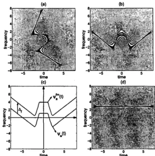
Fig. 3.
(a) The
WD
of the signal
:z:(t),
(b) the
WD
of the
a =(-0.8)1b
order FrFT
:Z:a(t)
of
:z:(t),
(c) the spines
"'a(t), ",lm(t)
of the signals
:z:
..(t)
and
:z:£m(t)
=:Z:a(t)eJ2orA/C
for
dj =2.8,
(d) the
WD
of the warped signal
:z:�:C(t)
=:z:£m«(t».
�
tineL=====--_
�(b)�]
(c)
jt2
Fig. I.
(a)
Amodel
WD and(b)
the correspondingjUllWD model
I
oI----�+r---I
including inner-interference terms, (c)-(d) The
WDs
of the syn-
:-thesized signals by using the
WD
and MWO-based signal design
algorithms on the model
WD
given in (a), respectively.
(b)
Fig. 1.
(a)
Amodel
WD
andsupport
of expected interference
terms
in the desired signal,
(b)
the result of the MWD-based signal
design algorithm
onthe model
WD
given in (a).
tlma
Fig. 4.