MECHANOCHEMICAL RADICAL FORMATION IN
CELLULOSE BALL MILLING AND PRODUCTION OF
CELLULOSE-METAL NANOPARTICLES COMPOSITES
A THESIS SUBMITTED TO
THE GRADUATE SCHOOL OF ENGINEERING AND SCIENCE OF BILKENT UNIVERSITY
IN PARTIAL FULFILLMENT OF THE REQUIREMENTS FOR THE DEGREE OF MASTER OF SCIENCE IN CHEMISTRY By Özge BAYRAK December 2017
MECHANOCHEMICAL RADICAL FORMATION IN CELLULOSE BALL MILLING AND PRODUCTION OF CELLULOSE-METAL
NANOPARTICLES COMPOSITES By Özge BAYRAK
December 2017
We certify that we have read this thesis and that in our opinion it is fully adequate, in scope and in quality, as a thesis for the degree of Master of Science.
______________________________ Bilge BAYTEKİN (Advisor)
______________________________ Yunus Emre TÜRKMEN
______________________________ İrem EREL GÖKTEPE
Approved for the Graduate School of Engineering and Science:
______________________________ Ezhan KARAŞAN
i
ABSTRACT
MECHANOCHEMICAL RADICAL FORMATION IN
CELLULOSE BALL MILLING AND PRODUCTION OF
CELLULOSE-METAL NANOPARTICLES COMPOSITES
Özge BAYRAK M.S. in Chemistry Advisor: Bilge BAYTEKİN
December 2017
Cellulose is the most abundant biopolymer in nature, which contains linear chains of repeating D-glucose molecules connected by 𝛽-1,4-glycosidic linkages. Over the past decades, due to growing interest in sustainability and green chemistry, cellulosic materials have received much attention. Since cellulose is highly abundant, light weight, strong, biodegradable, and nonabrasive, composite materials including cellulose can be environmental friendly, biocompatible, low cost, low weight, and multifunctional. Cellulose composites including metal nanoparticles (cellulose-metal NPs composites) find application in many fields due to the combined properties of both metal NPs and cellulose matrices. However, current production methods of cellulose-metal NPs composites have generally multistep, long, and non-environment friendly procedures due to their requirement for hazardous chemicals to reduce the metal ion precursor and stabilize the metal NPs that form.
This thesis work focuses on the investigation of cellulose mechanoradicals formation produced by ball milling qualitatively and quantitatively with the changes occurred in cellulose samples after mechanical treatment, and using formed cellulose mechanoradicals as reducing agent to reduce metal cations in cellulose matrices to obtain cellulose-metal NPs composites. Firstly, formation of cellulose mechanoradicals -free radicals that are formed by the homolytic breaking of the bonds in cellulose chains under mechanical input (ball milling)- was analyzed
ii
qualitatively and quantitatively. Qualitative analysis of cellulose mechanoradicals by ESR spectroscopy showed that, formed radicals could be generally peroxyl and alkoxyl types. The numbers of mechanoradicals formed by milling cellulose samples (cotton and microcrystalline cellulose) in wet and dry conditions were detected by using DPPH solutions with UV-Vis spectroscopy. It was shown that, dry grinding method led to the higher number of mechanoradicals formation. Changes in cellulose samples occurred after milling probed by using SEM, XRD, and FTIR-ATR analyses were found to follow the mechanoradical formation. Due to more efficient grinding in dry conditions, with increasing milling time, the progressive decrease in fiber size leading more accessible regions with smaller particle size of cellulose samples, and forming mostly amorphous cellulose samples were observed. FTIR-ATR analyses of ground cellulose samples, especially dry ground samples, showed the breaking of intra and intermolecular hydrogen bonds and 𝛽-1,4-glycosidic linkages. Lastly, cellulose-metal NPs composites were produced by using cellulose mechanoradicals as reducing agent for the first time. The composites were characterized by SEM, EDX, XRD, and XPS analyses. Au, Ag, Pt, and Pd NPs in their metallic forms, and Cu NPs in its metallic form Cu0 or in 1+ oxidation state as Cu2O, and Co in 2+ oxidation state as CoO NPs are successfully produced in
cellulose matrices. This mechanochemical method can be proposed as a new and green method for cellulose-metal NPs composites production. Consequently, our findings can contribute to the area of mechanochemistry and composite materials.
Keywords: mechanoradicals, cellulose composites, ball milling, cryomilling, mechanochemistry
iii
ÖZET
BİLYELİ ÖĞÜTME İLE SELÜLOZDA MEKANOKİMYASAL
RADİKAL OLUŞUMU VE SELÜLOZ-METAL
NANOPARÇACIK KOMPOZİTLERİNİN ÜRETİMİ
Özge BAYRAK Kimya, Yüksek Lisans Tez Danışmanı: Bilge BAYTEKİN
Aralık 2017
Selüloz, tekrar eden 𝛽-1,4-glikosidik bağlarla birbirine bağlı D-glikoz moleküllerinden oluşmuş doğada en çok bulunan bir biyopolimerdir. Son on yılda sürdürülebilirlik ve yeşil kimya alanına olan artan ilgi nedeniyle selülozlu malzemeler dikkat çekmektedir. Selülozun bol miktarda bulunması, hafif, dayanıklı ve biyobozunabilir olması nedeniyle selüloz içeren kompozit malzemeler de doğa dostu, biyouyumlu, düşük maliyetli, hafif ve çok fonksiyonlu olabilmektedir. Metal nanoparçacıkları (NP) içeren selüloz kompozitleri (selüloz-metal NP kompoziti), metal NP ve selüloz matrisinin birleşmiş özelliklerinden dolayı birçok kullanım alanına sahiptir. Ancak selüloz-metal NP kompozitlerinin mevcut üretim metotları, metal iyonlarını indirgemek ve stabilize etmek için kullanılan zararlı kimyasalları gerektirdikleri için, genellikle çok adımlı, uzun ve çevre dostu olmayan yöntemler içermektedirler.
Bu tez çalışması, bilyeli öğütme ile selüloz mekanoradikalleri üretiminin kalitatif ve kantitatif olarak, mekanik etki sonrası selüloz örneklerinde meydana gelen değişiklerle birlikte incelenmesi ve üretilen selüloz mekanoradikallerinin metal katyonlarını selüloz matrislerinde indirgenmesi için indirgen madde olarak kullanılarak selüloz-metal NP kompozitlerinin elde edilmesine odaklanmaktadır. İlk olarak, selüloz mekanoradikalleri -selüloz zincirindeki bağların mekanik etki altında (bilyeli öğütme ile) homolitik olarak kırılması sonucu oluşan
iv
serbest radikaller- kalitatif ve kantitatif olarak analiz edilmiştir. ESR spektroskopisi ile yapılan kalitatif analiz, oluşan radikallerin genellikle peroksil ve alkoksil radikalleri olduğunu göstermiştir. Selüloz örneklerinin (pamuk ve mikrokristal selüloz) ıslak ve kuru koşullarda öğütülmesi ile oluşan mekanoradikallerin sayısı DPPH çözeltisi kullanılarak, UV-Vis Spektroskopisi ile tayin edilmiştir. Kuru öğütme yönteminin daha fazla sayıda mekanoradikal üretimine neden olduğu gösterilmiştir. Öğütme sonrasında SEM, XRD ve FTIR-ATR analizleri ile izlenilen selüloz örneklerinde meydana gelen değişikliklerin mekanoradikal oluşumu ile paralellik gösterdiği rapor edilmiştir. Kuru koşullarda öğütmenin daha etkili olmasından dolayı, artan öğütme zamanı ile selüloz liflerinin boyutlarının sürekli azalması sonucu erişilebilir alanların artması yanında daha küçük parçacık boyutlu selülozun ve çoğunlukla amorf selülozun oluştuğu gözlemlenmiştir. Öğütülmüş selüloz örneklerinin, özellikle de kuru olarak öğütülmüş örneklerin FTIR-ATR analizleri, moleküller içi ve moleküller arası hidrojen bağları ve 𝛽-1,4-glikosidik bağların kırıldıkları göstermiştir. Son olarak selüloz mekanoradikalleri ilk defa indirgen madde olarak kullanılarak selüloz-metal NP kompozitleri üretilmiştir. Bu kompozitler SEM, EDX, XRD ve XPS analizleriyle karakterize edilmiştir. Au, Ag, Pt ve Pd NP metalik formlarında, Cu NP metalik veya +1 yükseltgenme basamağında ve Cu2O
formunda, Co ise 2+ yükseltgenme basamağında ve CoO NP formunda selüloz matrislerinde başarıyla üretilmiştir. Bu mekanokimyasal yöntem, selüloz-metal NP kompozitleri üretimi için yeni ve yeşil bir metot olarak önerilebilmektedir. Sonuç olarak bulgularımız mekanokimya ve kompozit malzeme alanına katkı sağlayabilmektedir.
Anahtar sözcükler: mekanoradikaller, selüloz kompozitleri, bilyeli öğütme, soğuk öğütme,
v
ACKNOWLEDGEMENT
First and foremost, I would like to thank to my advisor Asst. Prof. Bilge Baytekin for not only for her excellent supervising and guidance throughout my studies. She always supported me throughout my research with her motivation, enthusiasm, patience, kindness, and unlimited energy. She was always open to new perspectives. The door to Asst. Prof. Bilge Baytekin was always open whenever I need her advices or I had a question or any problem. I will always remember her and the things she has thought me not only in academic areas but in all areas of life, in my future academic life, and follow her lead.
I would also like to thank to the examining committee members, Asst. Prof. Yunus Emre Türkmen, and Assoc. Prof. İrem Erel Göktepe, for their valuable time and feedback. I would also like to acknowledgement TÜBİTAK for the financial support under project no: 115Z452.
I am thankful to all of present and former Baytekin Research Group members; Doruk Cezan, Tutku Bedük, Atakan Arda Nalbant, and Rahym Ashirov for their friendships, and supports. I also wish to thank to my friends in chemistry department members; Pınar Alsaç, and Gülbahar Saat for their endless support and friendships. I also want to thank my dear friend Bedirhan Laçin for his endless support, and encouragement throughout my years of study.
Last but not the least, I would like to thank my parents Ayşe, and Nevzat Bayrak, and my sister İrem Bayrak for their unfailing support, love, sacrifices and continuous encouragement throughout my education and life.
vi
TABLE OF CONTENTS
CHAPTER 1 ... 1
INTRODUCTION ... 1
1.1 Cellulose: as a Promising Material ... 1
1.2 Brief History, Important Derivatives and Application Areas of Cellulose ... 1
1.3 Sources, Types, and Properties of Cellulose ... 4
1.4 Molecular and Supramolecular Structure of Cellulose ... 7
1.5 Cellulose Composites ... 12
1.5.1 Cellulose-Metal Nanoparticle Composites ... 13
1.5.1.1 Application Areas of Cellulose-Metal Nanoparticle Composites ... 15
1.6 Polymer Mechanochemistry ... 16 1.6.1 Polymer Mechanoradicals ... 18 1.7 Mechanochemistry of Cellulose ... 21 1.8 Aim of Thesis ... 22 CHAPTER 2 ... 25 EXPERIMENTAL ... 25 2.1 Materials ... 25
2.2 General Experiment Conditions and Setup ... 25
2.2.1 Wet Grinding of Cellulose Samples ... 26
vii
2.3 Experiment Conditions and Setup for Production of Cellulose–Metal NPs
Composites ... 28
2.4 Instrumentation ... 29
2.4.1 Cryomill ... 29
2.4.2 UV-Vis Spectroscopy Analysis ... 29
2.4.3 Scanning Electron Microscopy (SEM) and Energy Dispersive X-Ray (EDX) Analyses ... 29
2.4.4 Electron Spin Resonance (ESR) or Electron Paramagnetic Resonance (EPR) Spectroscopy Analysis ... 30
2.4.5 Fourier Transform Infrared Attenuated Total Reflectance (FTIR-ATR) Spectroscopy Analysis ... 30
2.4.6 X-Ray Diffraction (XRD) Analysis ... 30
2.4.7 X-ray Photoelectron Spectroscopy (XPS) Analysis ... 30
CHAPTER 3 ... 32
RESULTS & DISCUSSION ... 32
3.1 Investigation of Radical Production and Radical Amount ... 32
3.1.1 Quantitative Determination of Produced Radicals by UV-Vis Spectroscopy ... 32
3.1.1.1 Cellulose Mechanoradicals From Wet Grinding Method ... 33
3.1.1.2 From Dry Grinding Method ... 38
3.1.2 Qualitative Determination of Produced Radicals by Electron Spin Resonance (ESR) Spectroscopy Analysis ... 44
viii
3.2 Morphological Changes in Cryomilled Cellulose Samples by Scanning Electron
Microscopy (SEM) Analysis ... 47
3.2.1 Morphological Changes in Cryomilled Cellulose Samples by SEM Analysis - Wet Grinding Method ... 48
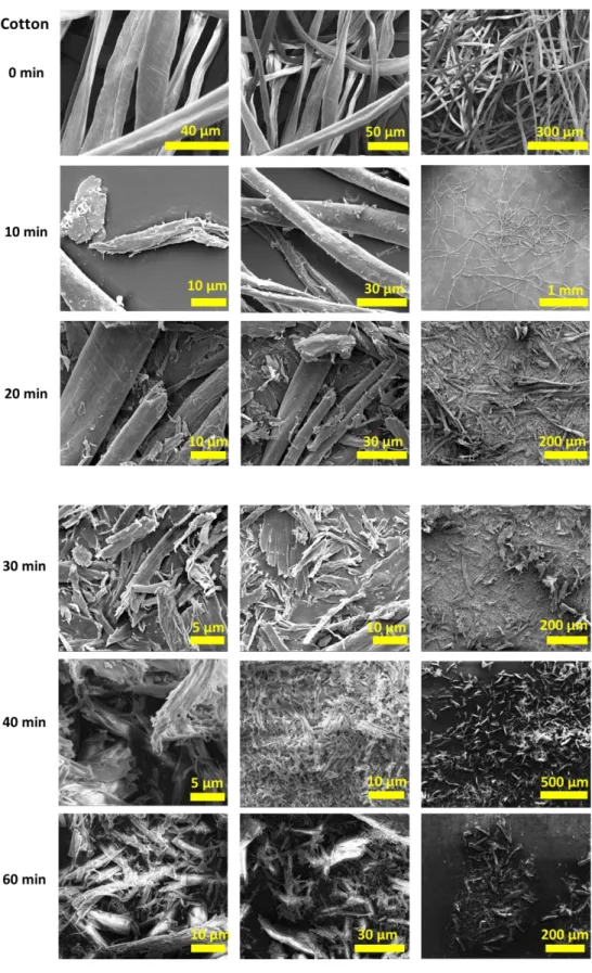
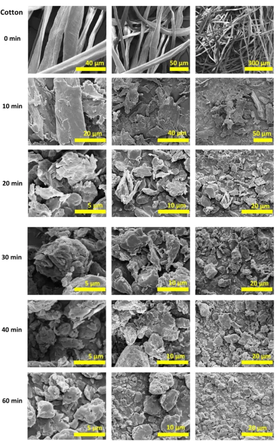
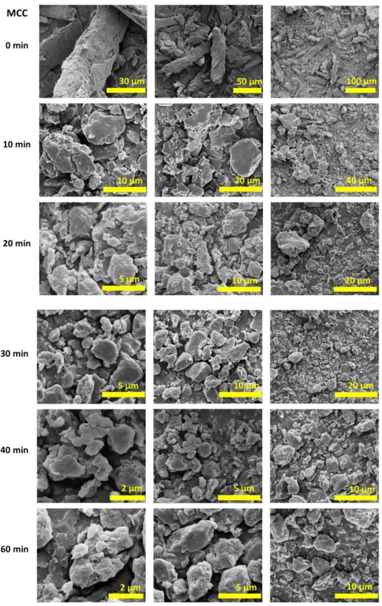
3.2.2 Morphological Changes in Cryomilled Cellulose Samples by SEM Analysis - Dry Grinding Method ... 51
3.3 Changes in Crystalline Structure of Cryomilled Cellulose Samples by X-Ray Diffraction (XRD) Analysis ... 54
3.3.1 Changes in Crystalline Structure of Cryomilled Cellulose Samples by XRD - Analysis Wet Grinding Method ... 54
3.3.2 Changes in Crystalline Structure of Cryomilled Cellulose Samples by XRD - Dry Grinding Method ... 60
3.4 Structural Changes of Cryomilled Cellulose Samples by Fourier Transform Infrared Attenuated Total Reflectance (FTIR-ATR) Spectroscopy Analysis ... 63
3.4.1 Structural Changes of Cryomilled Cellulose Samples by FTIR-ATR Spectroscopy Analysis - Wet Grinding Method ... 64
3.4.2 Structural Changes of Cryomilled Cellulose Samples by FTIR-ATR Spectroscopy Analysis - Dry Grinding Method ... 69
3.5 Production of Cellulose-Metal NPs Composites by in-situ Reduction with Cellulose Mechanoradicals ... 74
3.5.1 Cellulose-Gold Nanoparticles Composite ... 75
3.5.2 Cellulose-Silver Nanoparticles Composite ... 81
ix
3.5.4 Cellulose-Palladium Nanoparticles Composite ... 93
3.5.5 Cellulose-Copper Nanoparticles Composite ... 99
3.5.6 Cellulose-Cobalt Nanoparticles Composite ... 105
3.6 Possible Formation Mechanism of Cellulose-Metal NPs Composites ... 111
3.7 Crystalline Transformation from Cellulose I to Cellulose II ... 112
CHAPTER 4 ... 117
CONCLUSION ... 117
x
LIST OF FIGURES
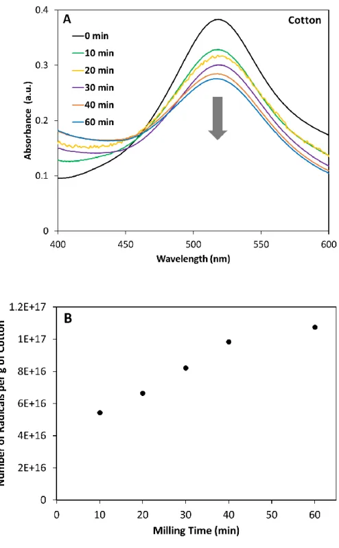
Figure 1. Morphological properties and structure of different types of cellulose [27]. ... 6 Figure 2. Molecular structure of cellulose (n: degree of polymerization)... 7 Figure 3. Cellulose chains forming inter and intramolecular hydrogen bonds. ... 9 Figure 4. Supramolecular arrangements of the chains of cellulose I and cellulose II crystalline structures [6]. ... 11 Figure 5. Schematic illustration of cellulose fibers. ... 12 Figure 6. The illustration of the formation of cellulose mechanoradicals on broken cellulose chain after cryomilling of cotton sample. ... 23 Figure 7. DPPH reaction with radical R●. ... 33 Figure 8. (A) UV-Vis spectra of the DPPH solutions (initial concentration after dilutions was 3.2x10⁻⁵ M) that were wet cryomilled (30 Hz frequency in the presence of 6 zirconia balls in the zirconia sample chamber at 77 K) with 500 mg cotton samples for 10, 20, 30, 40, and 60 minutes, and (B) calculated number of radicals per gram of cotton from the UV-Vis measurements for each milling time. ... 35 Figure 9. (A) UV-Vis spectra of the DPPH solutions (initial concentration after dilutions was 3.2x10⁻⁵ M) that were cryomilled (30 Hz frequency in the presence of 6 zirconia balls in the
zirconia sample chamber at 77 K) with 500 mg MCC samples for 10, 20, 30, 40, and 60 minutes, and (B) calculated number of radicals per gram of MCC from the UV-Vis measurements for each milling time. ... 36 Figure 10. (A) Number of radicals per gram of cotton calculated just after the addition of DPPH solutions (initial concentration after dilutions was 3.2x10⁻⁵ M) on dry cryomilled 500 mg of cotton samples for 10, 20, 30, 40 and 60 minutes of milling (30 Hz frequency in the
xi
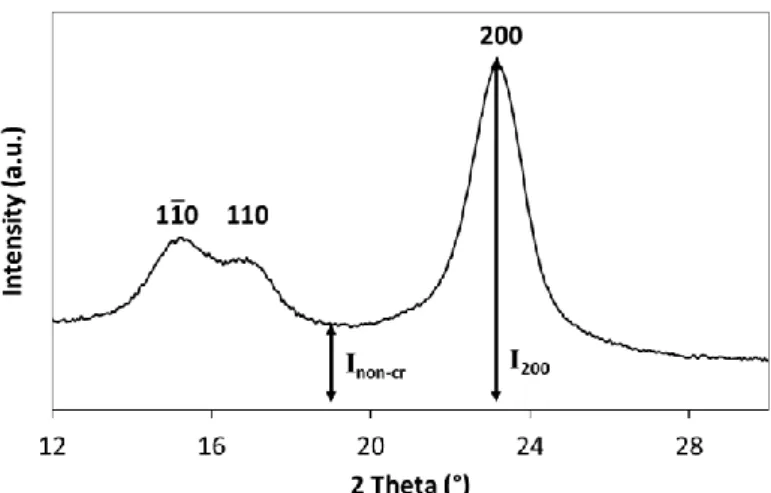
presence of 6 zirconia balls in the zirconia sample chamber at 77 K), and (B) number of radicals calculated after designated waiting times. ... 40 Figure 11. (A) Number of radicals per gram of MCC calculated just after the addition of DPPH solutions (initial concentration after dilutions was 3.2x10⁻⁵ M) on dry cryomilled 500 mg of MCC samples for 10, 20, 30, 40 and 60 minutes of milling (30 Hz frequency in the presence of 6 zirconia balls in the zirconia sample chamber at 77 K), and (B) number of radicals calculated after designated waiting times. ... 42 Figure 12. Structures of cellulose mechanoradicals produced by ball milling, Modified from [108], [119], [120]. ... 45 Figure 13. Room temperature ESR spectrum of cryomilled cotton (500 mg) sample (30 Hz frequency in the presence of 6 zirconia balls in the zirconia sample chamber at 77 K). ... 46 Figure 14. SEM images of cotton and wet cryomilled cotton (500 mg) samples (30 Hz frequency in the presence of 6 zirconia balls in the zirconia sample chamber at 77 K) for 10, 20, 30, 40, and 60 minutes. ... 49 Figure 15. SEM images of MCC and wet cryomilled MCC (500 mg) samples (30 Hz frequency in the presence of 6 zirconia balls in the zirconia sample chamber at 77 K) for 10, 20, 30, 40, and 60 minutes. ... 50 Figure 16. SEM images of cotton and dry cryomilled cotton (500 mg) samples (30 Hz frequency in the presence of 6 zirconia balls in the zirconia sample chamber at 77 K) for 10, 20, 30, 40, and 60 minutes. ... 52 Figure 17. SEM images of MCC and dry cryomilled MCC (500 mg) samples (30 Hz frequency in the presence of 6 zirconia balls in the zirconia sample chamber at 77 K) for 10, 20, 30, 40, and 60 minutes. ... 53 Figure 18. XRD pattern of cotton sample having the intensities used in peak height method for percent crystallinity analysis. ... 57
xii
Figure 19. XRD patterns of cotton and wet cryomilled cotton (500 mg) samples (30 Hz frequency in the presence of 6 zirconia balls in the zirconia sample chamber at 77 K) for 10, 20, 30, 40, and 60 minutes. ... 59 Figure 20. XRD patterns of MCC and wet cryomilled MCC (500 mg) samples (30 Hz frequency in the presence of 6 zirconia balls in the zirconia sample chamber at 77 K) for 10, 20, 30, 40, and 60 minutes. ... 60 Figure 21. XRD patterns of cotton and dry cryomilled cotton (500 mg) samples (30 Hz frequency in the presence of 6 zirconia balls in the zirconia sample chamber at 77 K) for 10, 20, 30, 40, and 60 minutes. ... 62 Figure 22. XRD patterns of MCC and dry cryomilled MCC (500 mg) samples (30 Hz frequency in the presence of 6 zirconia balls in the zirconia sample chamber at 77 K) for 10, 20, 30, 40, and 60 minutes. ... 63 Figure 23. FTIR spectrum of cotton with band assignments from corresponding literature (also in Table 7). ... 65 Figure 24. FTIR spectra of cotton and wet cryomilled cotton (500 mg) samples (30 Hz frequency in the presence of 6 zirconia balls in the zirconia sample chamber at 77 K) for 10, 20, 30, 40, and 60 minutes. ... 67 Figure 25. FTIR spectra of MCC and wet cryomilled MCC (500 mg) samples (30 Hz frequency in the presence of 6 zirconia balls in the zirconia sample chamber at 77 K) for 10, 20, 30, 40, and 60 minutes. ... 68 Figure 26. FTIR spectra of cotton and dry cryomilled cotton (500 mg) samples (30 Hz frequency in the presence of 6 zirconia balls in the zirconia sample chamber at 77 K) for 10, 20, 30, 40, and 60 minutes. ... 72
xiii
Figure 27. FTIR spectra of MCC and dry cryomilled MCC (500 mg) samples (30 Hz frequency in the presence of 6 zirconia balls in the zirconia sample chamber at 77 K) for 10, 20, 30, 40, and 60 minutes. ... 73 Figure 28. SEM images and EDX spectrum of the cotton-Au NPs composite, showing formed Au NPs as bright spots in the cotton matrix, and the presence of Au atoms in the chemical structure. ... 77 Figure 29. SEM images and EDX spectrum of the MCC-Au NPs composite, showing formed Au NPs as bright spots in the MCC matrix, and the presence of Au atoms in the chemical structure. ... 78 Figure 30. XRD pattern of (A) cotton-Au NP composite (blue line) in comparison to that of pure cotton (black line), and (B) MCC-Au NP composite (orange line) in comparison to that of pure MCC (black line). Diffraction lines for metallic gold Au0 with fcc structure are marked with stars. ... 79 Figure 31. Au 4f HIRES XPS spectra of the composites of (A) cotton-Au NPs, and (B) MCC-Au NPs. ... 80 Figure 32. SEM images and EDX spectrum of the cotton-Ag NPs composite, showing formed Ag NPs as bright spots in the cotton matrix, and the presence of Ag atoms in the chemical structure. ... 83 Figure 33. SEM images and EDX spectrum of the MCC-Ag NPs composite, showing formed Ag NPs as bright spots in the MCC matrix, and the presence of Ag atoms in the chemical structure. ... 84 Figure 34. XRD pattern of (A) cotton-Ag NP composite (blue line) in comparison to that of pure cotton (black line), and (B) of MCC-Ag NP composite (orange line) in comparison to that of pure MCC (black line). Diffraction lines for metallic silver Ag0 with fcc structure are marked with stars. ... 85
xiv
Figure 35. Ag 3d HIRES XPS spectra of the composites of (A) cotton-Ag NPs, and (B) MCC-Ag NPs. ... 86 Figure 36. SEM images and EDX spectrum of the cotton-Pt NPs composite, showing formed Pt NPs as bright spots in the cotton matrix, and the presence of Pt atoms in the chemical structure. ... 89 Figure 37. SEM images and EDX spectrum of the MCC-Pt NPs composite, showing formed Pt NPs as bright spots in the MCC matrix, and the presence of Pt atoms in the chemical structure. ... 90 Figure 38. XRD pattern of (A) cotton-Pt NP composite (blue line) in comparison to that of pure cotton (black line), and (B) of MCC-Pt NP composite (orange line) in comparison to that of pure MCC. Diffraction line (for 111 planes) for metallic platinum Pt0 with fcc structure is marked with a star. ... 91 Figure 39. Pt 4f HIRES XPS spectra of the composites of (A) cotton-Pt NPs, and (B) MCC-Pt NPs. ... 92 Figure 40. SEM images and EDX spectrum of the cotton-Pd NPs composite, showing formed Pd NPs as bright spots in the cotton matrix, and the presence of Pd atoms in the chemical structure. ... 95 Figure 41. SEM images and EDX spectrum of the MCC-Pd NPs composite, showing formed Pd NPs as bright spots in the MCC matrix, and the presence of Pd atoms in the chemical structure. ... 96 Figure 42. XRD pattern of (A) cotton-Pd NP composite (blue line) in comparison to that of pure cotton (black line), and (B) of MCC-Pd NP composite (orange line) in comparison to that of pure MCC. Diffraction line (for 111 planes) for metallic palladium Pd0 with fcc structure is marked with a star. ... 97
xv
Figure 43. Pd 3d HIRES XPS spectra of the composites of (A) cotton-Pd NPs, and (B) MCC-Pd NPs. ... 98 Figure 44. SEM images and EDX spectrum of the cotton-Cu NPs composite, showing formed Cu NPs as bright spots in the cotton matrix. The presence of Cu atoms in the chemical structure is only slightly seen in the EDX spectrum. ... 101 Figure 45. SEM images and EDX spectrum of the MCC-Cu NPs composite, showing formed Cu NPs as bright spots in the MCC matrix. Cu atoms are not seen in the EDX spectrum, presumably because of their low density in the cellulose matrix. ... 102 Figure 46. XRD pattern of (A) cotton-Cu NP composite (blue line) in comparison to that of pure cotton (black line), and (B) of the MCC-Cu NP composite (orange line) in comparison to that of pure MCC. Because of the low amount of the Cu (Cu2O) NPs in the matrices, the
crystal lines are not visible in the XRD diffractograms. ... 103 Figure 47. Cu 2p HIRES XPS spectra of the composites of (A) cotton-Cu NPs, and (B) MCC-Cu NPs (B). ... 104 Figure 48. SEM images and EDX spectrum of the cotton-Co NPs composite, showing formed Co NPs as bright spots in the cotton matrix. The presence of Co atoms in the chemical structure is only slightly seen in the EDX spectrum. ... 107 Figure 49. SEM images and EDX spectrum of the MCC-Co NPs composite, showing formed Co NPs as bright spots in the MCC matrix. The presence of Co atoms in the chemical structure is only slightly seen in the EDX spectrum. ... 108 Figure 50. XRD pattern of (A) cotton-Co NPs composite (blue line) in comparison to that of pure cotton (black line), and (B) of the MCC-Co NPs composite (orange line) in comparison to that of pure MCC. Because of the low amount of the Co (CoO) NPs in the matrices, the crystal lines are not visible in the XRD diffractograms. ... 109
xvi
Figure 51. Co 2p HIRES XPS spectra of the composites of cotton-Co NPs (A), and MCC-Co NPs (B), implying that MCC-Co atoms are deposited as MCC-Co2+. See text for further discussion on XPS spectra. ... 110 Figure 52. Representation of the production of cellulose-metal NPs composites by cryomilling. ... 112 Figure 53. XRD patterns of the cotton sample and the composites of Au, Ag, Pt NPs in cotton matrix. Stars indicate the diffraction lines coming from cellulose II structure. ... 115 Figure 54. XRD patterns of the cotton sample and the composites of Pd, Cu, Co NPs in cotton matrix. ... 115 Figure 55. XRD patterns of the MCC sample and the composites of Au, Ag, Pt NPs in MCC matrix. Stars indicate the diffraction lines coming from cellulose II structure. ... 116 Figure 56. XRD patterns of the MCC sample and the composites of Pd, Cu, Co NPs in MCC matrix. ... 116
xvii
LIST OF TABLES
Table 1. Examples of cellulose sources from plant origins. ... 5 Table 2. General application areas of cellulose-metal NPs composites [27]. ... 16 Table 3. Types of mechanoradicals formed under mechanical input in different mediums [99]. ... 20 Table 4. Numbers of the mechanoradicals per gram of cellulose formed by wet grinding of (500 mg) cotton and MCC samples (30 Hz frequency in the presence of 6 zirconia balls in the zirconia sample chamber at 77 K) for 10, 20, 30, 40, and 60 minutes. ... 38 Table 5. Number of mechanoradicals per gram of cotton formed by wet and dry cryomilling of 500 mg cotton samples (30 Hz frequency in the presence of 6 zirconia balls in the zirconia sample chamber at 77 K) and their ratio at 10, 20, 30, 40, and 60 minutes milling time. ... 41 Table 6. Number of mechanoradicals per gram of MCC formed by wet and dry cryomilling of 500 mg MCC samples (30 Hz frequency in the presence of 6 zirconia balls in the zirconia sample chamber at 77 K) and their ratio at 10, 20, 30, 40, and 60 minutes milling time. ... 43 Table 7. FTIR band assignments for cotton and MCC samples from corresponding literature. ... 66
xviii
LIST OF ABBREVIATIONS
VC: Vegetable Cellulose BC: Bacterial Cellulose NFC: Nanofibrillated Cellulose DPPH: 2,2-Diphenyl-1-picrylhydrazyl MCC: Microcrystalline Cellulose SEM: Scanning Electron Microscopy EDX: Energy Dispersive X-ray ESR: Electron Spin ResonanceEPR: Electron Paramagnetic Resonance XRD: X-ray Diffraction
XPS: X-ray Photoelectron Spectroscopy
FTIR-ATR: Fourier Transform Infrared Attenuated Total Reflectance NP: Nanoparticle
NPs: Nanoparticles
C: Crystallinity or Crystallinity Index fcc: Face Centered Cubic
hcp: Hexagonal Close Packed
SERS: Surface Enhanced Raman Scattering HIRES: High Resolution
1
CHAPTER 1
INTRODUCTION
1.1 Cellulose: as a Promising Material
In recent times, due to the problems of petroleum deficiency and environmental pollutions resulted from non-degradable polymers, there has been a great interest in products obtained from renewable, environmentally friendly and sustainable resources. At this point cellulose has become a promising material. It is the most abundant biopolymer in the world with its annual production of around 1012 tons [1], [2]. In addition to high abundance of cellulose, it has many desirable properties. Despite its high strength, stiffness, good mechanical properties, it has low cost due to worldwide availability [3]. Its properties of biodegradability, renewability, low abrasive and nontoxic nature, low density and low weight make cellulose polymer a good chemical for being used in composite or cellulose based materials [4]. Moreover, using cellulose in structural engineering materials is proper due to its rigidity, high crystallinity, and insolubility in common organic solvents [5], [6].
1.2 Brief History, Important Derivatives and Application Areas of
Cellulose
After the French chemist Anselme Payen in 1838 did an experiment with the tissue of plants and woody materials by applying different treatments using various acids and bases, he recognized that, the plants’ cell wall composed of the same
2
substance, which is cellulose [3], [7], [8]. The name of cellulose as a term was used by the French Academy in a report including Payen’s work in 1839 [9], [10]. In 1920 Hermann Staudinger identified cellulose structure as a polymer consisting of repeating glucose units connected to each other by covalent bonds [11], [12].
Before the discovery of cellulose in cell wall of plant cells, it was used generally in the form of wood and cotton and other plant fibers. For almost 200 years, cellulose has been used in various applications as a raw material in pulps, papers, cardboards, building materials, textiles, composites, personal care products, and in pharmaceutical industry [7], [9]. With the improvements achieved in chemical methods, cellulose could be extracted from plants and then modified with various chemical groups. These modified celluloses or cellulose derivatives also have extensive application areas. In 1832 cellulose nitrate (also known as nitrocellulose, guncotton) was discovered by esterification reaction with nitric acid. Cellulose acetate, cellulose acetate butyrate and propionate are now other important cellulose ester derivatives [11]. In 1870 the first thermoplastic polymer called celluloid was produced by Hyatt Manufacturing Company using nitrocellulose, camphor, and other additives. Rayon (known as artificial silk), cellophane (known as viscose), carboxymethyl cellulose (cellulose gum), methyl cellulose, and hydroxyalkyl cellulose are other important derivatives of cellulose. These kinds of derivatives are also called as “first-generation cellulosic material” or “traditional cellulosic material”. All these produced cellulose derivatives have shown that, modification of the cellulose structure is possible. With modified cellulose samples, the application areas including cellulosic materials can be increased. For example, in the production of optical films, filters, coatings, cosmetics, foods additives, and laminates, cellulosic materials have been used [1], [7], [13]. These first-generation
3
materials produced from cellulose are among the material groups, which are commonly used worldwide. There are fair enough reasons of such an inclination towards cellulose and materials produced from cellulose. For instance, cellulose is natural and the most abundant polymer in the world, cellulosic materials are much lighter than their equivalents, there is considerable amount of knowledge on chemical, physical, electrical and mechanical properties of cellulose, and it is the raw material that can be used in wide range of areas from textile to industrial productions. Apart from the traditional cellulosic materials produced from cellulose mentioned above, it is also possible to produce extraordinary but very useful materials for humanity. As an example, for such materials “diagnostic sheet” can be made mention of. This material is produced by saturation of sheets with biochemical materials and it can provide early diagnosis of critical diseases. These diagnosis kits are made up of paper. Therefore, diseases can be diagnosed easily, quickly and cheaply without needing complex medical equipment and procedures. Thus, they can be used in the regions like Africa and South Asia where access to medical supply and services are limited. The other technology product like “diagnosis sheet” is “paper robots”. These are produced by using cellulose-based materials, which make them lighter than the other robots, and thus they will be much more energy-efficient and easier to use. The products for point of care diagnostics such as urine, diabetes, and pregnancy test strips, paper chromatography for detection of amino-acids in protein [14], paper based microfluidics [15], paper based bioassay for detection of glucose in urine [16], paper based immunoassays [17], [18], and pathogen detection [19], [20] can be given as the examples of paper based technology products [6]. It is crucial to easily
4
obtain cellulosic (composite) materials for all of these applications and for future technologies.
1.3 Sources, Types, and Properties of Cellulose
Cellulose is present on the cell walls of almost all plants as a structural component. Cotton linters (as plant source) and wood pulp are used as the conventional cellulose sources [21]. Turkey is one of the largest cotton producer country in the world. More than 90% of cotton and 40%-50% of wood are cellulose. Cellulose in cotton is almost pure, but in woody plants it is present with other materials such as lignin and hemicellulose [7], [21]. Although the whole structure of lignin has not clearly defined yet, it is a polymer with nonlinear structure and phenyl propanoid units. While cellulose forms the main skeleton of the wood, lignin acts as a cement binding the cells of the wood together. It attaches to the hemicellulose covalently and it gives stiffness and rigidity to woody plants [6], [21]. Hemicellulose is a heteropolymer with branched chains of many different sugar units such as glucose, mannose, galactose. Its sugar units differ for all plants. It provides the compatibility between cellulose and lignin in plants [6]. In addition to plants, cellulose is also obtained from some marine animals, algae, fungi, bacteria, and amoeba [9]. Cellulose’s annual production is around 1012 tons, and it is seen as ‘an inexhaustible raw source’ [1], [2]. Thus, the cellulose sources can be grouped into plant, wood, tunicate, algae and bacteria [1]. Plant sources could be reclassified according to their origins [3]. These are summarized in Table 1.
5
Table 1. Examples of cellulose sources from plant origins.
Cellulose can be extracted from plant sources with purification. In addition to wood as mentioned before, tunicates are another cellulose source. They are sea animals having a shell containing cellulose polymer in a protein matrix. They are also called as “sea squirts” (Ascidiacea). The most used tunicate species as a cellulose source are Metandroxarpa uedai [22], Halocynthia roretzi [23], and
Halocynthia papillosa [1], [24], [25]. Cellulose can also be produced by some
green, red, and grey algae species such as Boergesenia, Valonia, Caldophora [1]. Lastly, cellulose can be secreted by some bacteria called Gluconacetobacter xylinus [1], [26].
Cellulose samples used for composite preparation can also be classified as vegetable cellulose (VC), bacterial cellulose (BC), and nanofibrillated cellulose (NFC) in terms of morphological and mechanical characteristics [27]. BC and NFC have nanosized fibers, which leads to new properties gained by the composites containing BC and NFC. There is an increasing interest towards using BC in composites and other application areas such as food and medical industry due to its desirable properties. The properties of crystallinity (60-90%), purity, degree of
6
polymerization (up to 8000), mechanical stability, elasticity, and water content are high [7], [26]–[30]. With the developed methods including chemical treatments cellulose can be obtained as nanofibers called NFC from VC sources. NFC is obtained as an aqueous suspension. It has high aspect ratio with the fibers with 5-30 nm diameters and micrometer lengths. Moreover, it is highly attractive due to its characteristics such as high surface area (>100m2/g), low density (1.6 g/cm3), high strength and flexibility, and low thermal expansion. In short, the types of cellulose obtained from different sources display different properties.
Figure 1. Morphological properties and structure of different types of cellulose
[27].
Apart from these some differences observed in the types of cellulose mentioned above, cellulose fibers have generally desirable properties. They possess excellent tensile strength, elastic modulus, , low density, and high durability [3]. For example, the mechanical characteristics of the fibers obtained from wood and flax are similar with E-glass fibers that are alumino-borosilicate glass fibers used
7
mainly in glass reinforced plastics. Therefore, cellulose fibers have been used as the reinforcing agents in polymer composites, as well. In addition, they show recyclability, good moldability, biodegradability, renewability, low abrasive, and nontoxic nature. It should be noted that, the properties of fibers are affected by some factors such as cellulose source and the conditions of purification or extraction processes. Therefore, it can be possible to obtain cellulose fibers with desired and modified properties.
1.4 Molecular and Supramolecular Structure of Cellulose
The interesting properties cellulose result from its specific chemical structure. Cellulose (poly (β-1,4-D-anhydroglucopyranose) is a natural linear polymer, with a structure shown in Figure 2.
Figure 2. Molecular structure of cellulose (n: degree of polymerization).
Cellulose is composed of repeating units of two connected β-D-anhydroglucopyranose rings (β-D-glucose rings) [9]. The degree of polymerization value of cellulose can be in the range of 300-15000, depending on cellulose source and extraction process. For example, for cotton and other plant sourced cellulose samples this value is between 800-10000 [6]. β-D glucose molecules are connected
8
to each other by 1-4 glycosidic linkages. In other words, D-glucose rings are connected to each other through β-1-4 glycosidic linkages. These glucose molecules are linked when water is eliminated by combining -H and -OH groups. Therefore, the prefix of anhydro is used generally. When just two glucose molecules are connected to each other, a disaccharide called cellobiose forms. The 6-membered glucose rings in cellulose chains are called glucopyranose rings. They are connected through the oxygen atoms (ether bond, acetal link) between the equatorial group of C1 (anomeric) carbons of one glucopyranose ring and C4 carbons of the adjacent ring, which forms cellulose polymer. The stereochemistry the group at C1 carbon determines the whether the polymer is in α or β anomeric form. In cellulose structure, the oxygen atom at C1 carbon is at equatorial position, leading to β-linkage. Therefore, this linkage is called as β-1,4 glycosidic link.
The equatorial position of the groups at C1 carbon and of the all other groups at carbon atoms on the ring leads to the linear alignment of the cellulose chains, which makes cellulose a good fiber forming polymer. Because of this linearity of the cellulose chains, the groups on the rings can approach together. Therefore, the hydroxyl groups on the chains can easily form strong hydrogen bond networks between and within the cellulose chains, which provides cellulose polymer high cohesive energy. Figure 3 represents the cellulose chains forming inter and intramolecular hydrogen bonds for common native cellulose (cellulose I).
9
Figure 3. Cellulose chains forming inter and intramolecular hydrogen bonds.
As can be seen in Figure 3, there are intramolecular hydrogen bonds between the atoms of O(3)H-O(5) and O(2)H-O(6), and intermolecular hydrogen bonds between the atoms of O(6)H-O(3) [6]. These hydrogen bonding networks determine the physical properties of cellulose. Due to these intramolecular hydrogen bonds, cellulose chains have linear configurations. Moreover, these bonds stabilize the glycosidic linkages, and provide thermal stability and good mechanical properties. Intermolecular hydrogen bonds also lead to strong cellulose fibers with insoluble nature [3]. The parallel aggregation or stacking of the cellulose chains forming cellulose fibrils arises from the combined effect of intermolecular hydrogen and van der Waals forces [1]. The regularity of these bonds might determine the ordered or disordered regions in cellulose chains. Therefore, the different crystalline structures (allomorphic forms of cellulose) are originated because of different supramolecular arrangements resulted from different hydrogen bonding formations. Thus, both inter- and intramolecular hydrogen bonds provide the cellulose fibers the characteristic properties of high stiffness and chains with parallel arrangements.
10
There are four known polymorphic or allomorphic forms of cellulose crystallites. These are cellulose I, II, III, and IV. Native cellulose found in nature has cellulose I crystalline structure that has chains with parallel orientations. Cellulose II shows antiparallel orientations of chains. It is energetically more stable. Cellulose III has two forms, which are cellulose IIII and cellulose IIIII. These are
produced from cellulose I and cellulose II, respectively. Liquid ammonia or some amine derivatives are used to produce cellulose III. Two forms of cellulose IV that are cellulose IVI and cellulose IVII are produced from cellulose IIII and cellulose
IIIII, respectively. High temperature treatment (260 oC) in glycerol is applied for
production of cellulose IV [31], [32], [2]. Among these forms of cellulose, cellulose I and cellulose II have become focus of interest. The transformation from cellulose I to cellulose II was achieved by mercerization process, which is alkalization of cellulose I with sodium hydroxide and regeneration of cellulose II, and by treatment of cellulose I in subcritical water [33], [34], [35], [31]. Moreover, amorphous cellulose that still has cellulose I structure was recrystallized to cellulose II by water absorption and heat treatment [36]–[38]. Different supramolecular arrangements of cellulose chains form the different crystalline structures, as mentioned above. The specific crystalline structures of cellulose I and cellulose II are attributed to different intermolecular hydrogen bonds they have. The intramolecular hydrogen bonds O(3)H-O(5) are common for both crystalline form, but the O(2)H-O(6) bonds present in only cellulose I structure. While the intermolecular hydrogen bonds at O(6)H-O(3) occur in cellulose I, the O(6)H-O2 bonds present in cellulose II structure, which can be seen in Figure 4.
11
Figure 4. Supramolecular arrangements of the chains of cellulose I and cellulose II
crystalline structures [6].
Cellulose has both crystalline regions having extensive hydrogen bonding and amorphous regions having week hydrogen and van der Waals interactions. These regions can be shown as in Figure 5, cellulose fibers possessing ordered and disordered regions. The chemical reactivity and accessibility of cellulose are hindered by its high crystallinity. Therefore, pretreatment processes leading to the decrease in cellulose crystallinity have been applied to cellulose samples to obtain better reactivity and efficient reaction. To decrease crystallinity of cellulose, applied processes are ball milling [39], liquid acid and base treatments [40], [41], [42], and microwave irradiation treatments [43], [44], [45].
12
Figure 5. Schematic illustration of cellulose fibers.
1.5 Cellulose Composites
In recent years, with the developments in material field, cellulose has started to be the center of interest in producing cellulose particles and composite materials, which are also called as “new generation cellulose materials”. These new generation cellulose materials differ considerably from traditional materials by means of mechanical and physical features as well as in their area of utilization. Composite materials possess the properties of the constituent materials they have. In other words, they show combined properties. Because of the desirable properties of cellulose, its composites have been produced to impart the features coming from cellulose itself. Petroleum deficiency and environmental concerns led to a great interest on products obtained from renewable, environmentally friendly and sustainable resources. Therefore, composite materials including cellulose, which
13
are environmentally friendly, biodegradable, renewable, low abrasive and nontoxic nature have been getting an increased attention [1]–[5].
Cellulose materials have other advantageous properties, too. Good mechanical properties, low cost, low weight, and low density are some of these properties. As striking examples showing excellent properties of cellulose materials, one might show; nanofibers of cellulose in crystal state resemble Kevlar polymer with respect to Young’s modulus, and cellulose in the form of nanoparticles shows higher tensile strength than cast iron [46]. Having the edge on diverse range of applications due to the mentioned features, the number of studies on both new generation cellulose and their composites is rising day by day. Soon, it is expected that applications of these materials can be improved in the areas such as antimicrobial and transparent films, flexible screens, reinforcement for polymeric materials, biomedical implants, pharmaceutical materials, drug delivery systems, textiles, and batteries.
1.5.1 Cellulose-Metal Nanoparticle Composites
The films including metal nanoparticles (NPs) have begun to get more attention progressively due to their use in many areas. Depending on features of metal ion they include, these composites can be used, for instance, in anti-bacterial textile and kitchenware [47], [48], medical devices [49], electronic parts [50], [51]. Similarly, cellulosic composites bearing metal NPs as the filler material find application in many fields spanning from diagnostics to state-of-the art new generation paper robots due to their light and multifunctional nature. The properties of cellulose- metal NPs composites depend on the metal NPs employed as fillers and on the type of cellulose matrix used. Therefore, it is possible to make materials
14
with combination of different properties and biocompatibility due to cellulose matrix [52]. For example, silver NPs in cellulose matrix give the antimicrobial properties to the composite, so that it can be used in applications of artificial skin, food packaging, water treatment [27]. Gold, platinum, palladium, copper NPs enable to be used cellulose composites in catalytic applications [27].
In order to prepare such composites, diverse methods were developed. Some of these methods are electrostatic assembly [53]–[56], surface pre-modification of cellulose [57], [58], blending of components [59]–[61], and reduction of metal NPs by adding external reducing agents [56], [61]–[65], by using UV light [66], and by using high temperature conditions some chemical treatments [67]–[69].
Among these preparation methods, the most popular one is the one in which metal ions are reduced in cellulose matrix with external reducing agent to obtain metallic NPs in the matrix, and stabilizers are used to prevent NPs from aggregation. Due to the reducing chemical use, this method is toxic and environmentally hazardous. Moreover, the method necessitates generally multi-step and long processes, and the chemicals used in the method lead to contamination in later applications; e.g., if the composite material is to be used in the sensor field, the contaminations lead to unreliable measurements with the sensor. Another common method for preparation of cellulose-metal NPs composites is reducing the metal ions with UV light. This method is straightforward and contamination-free but it can only be used for Ag NPs.
An efficient “green synthesis” that uses mechanochemical method to form such cellulose-metal NPs composites, possessing advantages of 1) having ‘naked’ nanoparticles (without using stabilizers), 2) using cellulose mechanoradicals
15
formed by mechanical action to reduce the metal ions (without using external reducing agents) 3) in a straightforward way (no multistep procedures) is shown in this thesis.
1.5.1.1 Application Areas of Cellulose-Metal Nanoparticle
Composites
As mentioned above, cellulose-metal NPs composites bare the characteristics of the metal NPs embedded in them, so they can be used in applications emerging from these properties. Therefore, with changing metal NPs in cellulose matrix, the properties and application areas of the composite can be changed. These application areas are summarized in Table 2. The most notable characteristics of the metal NPs in cellulose matrix are; anti-microbial/anti-fungal characteristics of Ag and Cu NPs, catalytic action of Au, Ag, Pt, Pd, Cu NPs and magnetic property of Co NPs. Also, as Au and Ag NPs was proven suitable for Surface Enhanced Raman Scattering (SERS), composites made of the mentioned NPs are convenient for chemical and biochemical detection platforms. When these features of Au and Ag particles are joined with easy-accessibility, biocompatibility and cheapness of the cellulose matrix, ideal material could be obtained for sensor applications [59], [70]. Cellulose-metal NPs composites’ features do not only depend on metal NPs they include, but also on cellulose type (VC, BC or NFC) [27]. For instance, when the composite of Ag NPs in BC matrix was compared with the composite of Ag NPs in VC matrix, the former surpassed the latter in terms of detection of amino acids [71]. For this very reason, in addition to using different metal cations, at the same time, we aim to work with two different cellulose matrices (cotton and microcrystalline cellulose (MCC)) and to compare these composites in our project.
16
Table 2. General application areas of cellulose-metal NPs composites [27].
1.6 Polymer Mechanochemistry
Mechanochemistry as a research field examines the chemical transformations induced by mechanical force such as friction, stress, deformation, milling or grinding. Polymer mechanochemistry is based on breaking of long polymer chains, with mechanical effect such as pulling, bending, pressing, milling or grinding [72]– [75]. Although the history of the method reaches back to Staudinger’s mastication experiments (“mastication”, making chemical reaction by pressing) [76], [77], it can be said that, innovative research in polymer mechanochemistry have been conducted only in the last decades.
The studies on polymer mechanochemistry can be categorized in two groups: In the first group, chemical groups, which can selectively react upon mechanic effect in the mentioned polymer chains (called as mechanophores), are added into
17
the polymer chains by organic synthesis, and polymers are exposed to mechanical effect to observe polymer’s reactions [78]–[82]. With these studies, it was shown that some products were produced, which could not have been obtained previously through thermal and photochemical methods (e.g. anti-Woodward-Hoffmann products), and new methods were developed.
In the second group of studies [83], [84], easy-accessible and synthetic general-use polymers are used. Mechanochemical reactions are made by exposing polymers to pulling, pressing and rubbing, and through mechanical effect, homolytic and heterolytic chemical bond breakages take place in the bulk or on the surface of the polymer. Homolytic bond-breakage leads to mechanoradicals (polymer radicals formed through mechanic effect), and heterolytic bond cleavage leads to mechanoions (polymer cations and anions formed through mechanic effect). This second group of studies showed that through mechanochemistry of general polymers (without any specially designed mechanophores) it is possible; to change rheologic features of rubber, to obtain intended output of molecular weight [85]–[87], to dehalogenate environmentally hazardous halogenated polymers [88], to polymerize and co-polymerize synthetic polymers [89] and in mechanochromism [90], to obtain conductive polyaniline on other polymer surfaces [91], to activate and pattern adhesive surfaces toward nanoparticle deposition [92], and to drive lab-scale chemical reactions with mechanoradicals [84], [93].
General-use polymers have cumulative production amounts of 245 million tons and their sales reach up to 454 billion dollars annually with growth rate between 2012 and 2017 of 3.8% (2009, World polymer production) [94]. Mechanochemistry of polymer materials, have begun to be attractive research field,
18
because of this large ‘feedstock’ and also because of the diverse applications of polymer materials. For all that researches conducted in the last decades, still polymer mechanochemistry studies are not sufficient enough, to uncover the real potential of the mechanochemical method.
1.6.1 Polymer Mechanoradicals
Polymer mechanoradicals (products of homolytic mechanochemical polymer chain scission) were firstly detected and identified in 1960-1970s with the enhancement of the Electron Spin Resonance (ESR) method. “Mechanoradical” term was first used by Sohma [95] and it was defined as radicals produced by mechanical impact. The first and subsequent research on mechanochemical bond-breakages were conducted by Butyagin, Tomashevskii, Peterlin, DeVries, Kausch and Sohma, in polymers such as polypropylene [96], poly(tetrafluoroethylene) (PTFE) [97], polyethylene [98], poly(vinyl chloride), poly(vinylidene chloride), poly(oxymethylene), poly(ethylene terephthalate), poly(caprolactone), and the formation of mechanoradicals were analyzed. In Table 3, a summary of these efforts, i.e. formation methods of mechanoradicals in polymers, ambient conditions, types of bonds broken through mechanic effect, chemicals composition of consisted primary mechanoradicals and the methods used to observe consisted mechanoradicals are shown [99]. In short, to form mechanoradicals in polymers, ball milling, mastication, ultrasound waves and extrusion are used as primary methods.
If we would think about a reaction, in which the mechanically formed radicals can be used, we would come up first with the idea to use these mechanoradicals as initiators to launch polymerization of some monomer. A few examples of such
19
studies can be found in the literature, where mechanoradicals formed at the surface of poly(tetrafluoroethylene) (PTFE), were used to (co)polymerize methyl methacrylate, vinyl acetate and ethylene [97]. The formed copolymer hosts the features of each of the two polymer components. As it can clearly be seen from these studies, mechanoradical formation is an effective and straightforward method in making surfaces functional or to make reactions in the surfaces.
Mechanoradical formation was also found to be critical for the static electricity research. Static electrification, accumulation of static charges on polymers, is a big problem faced in industry. With two studies published in Science it was shown that mechanoradicals (the uncharged species) and mechanoions (the charges on the polymer surfaces) interact with each other and removal of mechanoradicals ceases static charge accumulation on surfaces. With these studies, the academical and technological interest in polymer mechanochemistry field was revived [100], [101].
The earlier studies of Baytekin et. al in the field of polymer mechanochemistry were inspirational for the topic of this thesis [84], [91]–[93]. In one of these studies elastomeric polymers were exposed to simple mechanical input, such as squeezing by hand, to produce mechanoradicals within the polymers. These mechanoradicals then migrated and led to the formation of hydrogen peroxide H2O2 at polymer-water interface, when the polymers are exposed to water.
This H2O2 could then drive the several chemical reactions e.g. gold nanoparticle
synthesis, bleaching of an organic dye, formation of a fluorescence with dye from its non-fluorescent derivative [84], [93]. Exposing the mechanically treated polymers to water, one can make use of mechanoradicals but mechanoions are eliminated in reactions with water. In a subsequent study, this time, without using
20
water, but now in organic solvents, it was shown that, the created mechanoions could make nonconductive polyaniline conductive [91]. In more recent studies from Baytekin group, gold, palladium, copper and silver nanoparticles were produced by the mechanoradicals formed on the surface of adhesive tapes after mechanical pulling [92]. So far, all these studies included synthetic polymers and no biopolymer. This thesis focuses on using a biopolymer (cellulose) to drive similar reactions.
Table 3. Types of mechanoradicals formed under mechanical input in different
21
1.7 Mechanochemistry of Cellulose
Biopolymer mechanochemistry is as much attractive and applicable as synthetic polymer chemistry. Mechanical effect upon high pressure homogenization and milling/purifying has sizably used to obtain cellulose, from various natural sources mentioned above, through isolation. However, this method is rather a physical isolation than being a chemical reaction. It has been known since 1921 that, when cellulose is subjected to mechanical input, its fibrils disintegrated. However, it was also shown that, when cellulose was subjected mechanical input with ball milling, the intermolecular hydrogen bonds, and covalent bonds were broken and mechanoradicals were produced [102]–[104]. Thereby, it is possible to divide mechanochemistry of cellulose into two as; 1) breaking of intermolecular bonds and 2) breaking of covalent bonds. Among these two groups, in the studies of the former, it was possible to make esterification reaction by using free OH groups formed after breaking hydrogen bonds in cellulose chains through mechanical effect [105]–[107]. In the second group of studies; mechanoradicals formed by ball milling were characterized by ESR, and mass spectrometry analyses [102]. The broken bonds by applying mechanical input in the cellulose chains are C-O-C glycosidic bonds and C-C bonds, forming alkyl (carbon centered) and alkoxyl (oxygen centered), and peroxyl radicals (if breaking takes place in oxygen atmosphere) [102].
In addition to the studies mentioned above, recent research also showed, by using cellulose mechanoradicals, formed by ball milling, it is possible to start polymerization of several monomers such as methylmethacrylate [108], [109], hydroxyethyl methacrylate [110], styrene [111] by using cellulose
22
mechanoradicals as polymerization initiators and to obtain cellulose-synthetic polymer copolymers.
1.8 Aim of Thesis
This thesis focuses on 1) the investigation of cellulose mechanoradicals produced by ball milling qualitatively and quantitatively, together with the changes occurred in cellulose structure during mechanical treatment, and 2) production cellulose-metal NPs composites by using cellulose mechanoradicals. Cellulose mechanoradicals are characterized qualitatively by using electron spin resonance spectroscopy (ESR) and this characterization is combined with the quantitative analyses of the mechanoradicals by using radical scavenger 2,2-Diphenyl-1-picrylhydrazyl (DPPH) molecule, using UV-Vis spectroscopy (first time in the literature with respect to cellulose mechanoradicals characterization and also with respect to using the method developed and used (dry grinding method) in ball milling studies). Moreover, the changes in cellulose structure after mechanical treatment is analyzed by using scanning electron microscopy (SEM), X-ray diffraction (XRD), fourier transform infrared attenuated total reflectance (FTIR-ATR) spectroscopy.
In this thesis, we are reporting formation of cellulose-metal NPs composites through formation of mechanoradicals. These composites are characterized by SEM, energy dispersive X-ray (EDX), XRD, and X-ray photoelectron spectroscopy (XPS). In the formation of composites, two cellulose samples are used; commercially available cotton and microcrystalline cellulose (MCC). They have different morphologies, and MCC is produced by mild acid hydrolysis, which will be discussed in next sections. By using two cellulose sources for both radical
23
production analyses and composites production, it is possible to see the effect of cellulose morphology on its mechanochemistry. Furthermore, for cellulose-metal NPs composites six different metal ion precursors are used with the two different cellulose sources (vide supra) as matrices, to obtain different combined properties. Mechanical input is applied to cellulose samples by using Retsch Cryomill, which has an integrated cooling system that enables us to do mechanochemistry at low temperatures, eliminating the heating of the sample (thermal reactions) and to elongate the life time of the formed radicals. Our starting point is illustrated in Figure 6, which basically shows the formation of cellulose mechanoradicals on broken fibers of cellulose after cryomilling.
Figure 6. The illustration of the formation of cellulose mechanoradicals on broken
cellulose chain after cryomilling of cotton sample.
As mentioned above in part 1.5.1, cellulose-metal NPs composite production methods usually involve multistep procedures and long processes, they are not environmentally friendly due to used chemicals such as stabilizing or reducing agents to form metal NPs. In this thesis work, cellulose mechanoradicals are used as reducing agent to produce metal NPs in cellulose matrices and both cellulose polymer chains and radicals are used as stabilizers of the in-situ formed ‘naked’
24
nanoparticles. Thereby, this research can be proposed as a “green”, mechanochemical method.
25
CHAPTER 2
EXPERIMENTAL
2.1 Materials
As cellulose sources, cotton (100% pure) from direct commercial source and microcrystalline cellulose (MCC) from Acros Organics were used. 2,2-Diphenyl-1-picrylhydrazyl (DPPH) and acetonitrile solvent were supplied by Sigma-Aldrich. DPPH stock solution in acetonitrile solvent was prepared for quantitative determination of the mechanoradicals by UV-Vis Spectroscopy. For the preparation of cellulose-metal nanoparticles composites, metal precursors: chloroauric acid HAuCl4, palladium (II) acetylacetonate Pd(C5H7O2)2, potassium (II)
tetrachloroplatinate K2PtCl4, cobalt (II) acetylacetonate Co(C5H7O2)2 and silver
nitrate AgNO3 from ABCR; copper (II) acetylacetonate Cu(C5H7O2)2 from Acros
Organics were utilized.
2.2 General Experiment Conditions and Setup
Samples are milled with 6 zirconia balls with 10.06 mm diameter as grinding medium in zirconia chamber using Retsch Cryomill instrument. In a typical experiment, the cellulose samples are milled at 30 Hz frequency for an indicated time at 77 K (cryo condition). This low temperature is achieved by liquid nitrogen that circulates through the milling chamber keeping the temperature at 77 K. Due to low temperature, life times of produced radicals can be enhanced and samples in
26
the chamber can be milled without sticking on the wall of the chamber. Moreover, using balls and chamber made up of zirconia allows us to mill the samples in the chamber without contamination due to wearing and sticking of zirconia on cellulose samples. Zirconia milling medium also prevents unwanted electron transfer between the milling medium and the reactants and rapid decaying of produced radicals.
2.2.1 Wet Grinding of Cellulose Samples
500 mg of cotton and MCC were separately milled with 2.5 mL of 1.3x10⁻⁴ M of DPPH solution prepared in acetonitrile solvent for 10, 20, 30, 40 and 60 minutes at 30 Hz frequency in the presence of 6 zirconia balls in the zirconia sample chamber at 77 K by using Cryomill instrument. At the end of the cryomilling for each indicated times, the mixture of cellulose source and DPPH solution were diluted to 10 mL by adding 7.5 mL of acetonitrile solvent in the sample chamber and the mixture was mixed at 5 Hz frequency for 30 seconds by using Cryomill instrument. By this way, the concentration of the DPPH solution became 3.2x10⁻⁵ M (as if DPPH were not consumed at all). Then, the mixtures of cryomilled cellulose and DPPH solution were taken into tubes and separated from each other by centrifugation. The liquid part of the mixture, containing DPPH solution cryomilled with cellulose source for indicated times, was used for quantitative analysis of the produced mechanoradicals by using UV-Vis Spectroscopy. Reference DPPH solution that has concentration of 3.2x10⁻⁵ M was prepared. From the difference of the absorbance of the reference DPPH solution and the cryomilled DPPH solution with cellulose source, the amount of produced mechanoradicals was calculated. The precipitate part of the mixture containing cellulose source was
27
washed several times and dried in vacuum. Then it was utilized to examine the morphological, structural, compositional changes and changes in crystal structure after milling for indicated times by using SEM, FTIR-ATR, XPS and XRD analyses.
2.2.2 Dry Grinding of Cellulose Samples
In a typical dry grinding experiment, 500 mg of the cellulose samples (cotton and MCC) were separately milled for 10, 20, 30, 40 and 60 minutes at 30 Hz frequency in the presence of 6 zirconia balls in the zirconia sample chamber at 77 K by using Cryomill. After the cryomilling, 2.5 mL of 1.3x10⁻³ M DPPH solution
prepared in acetonitrile solvent were added on to the milled sample. (In an initial experiment, after dry grinding of cellulose source for 60 minutes, 2.5 mL of 1.3x10
-4 M DPPH solution was added to the sample chamber and it was observed that dark
purple color of the DPPH solution immediately turned into yellow color, as it came into contact with cryomilled cellulose source, which meant that all DPPH radicals were depleted by cellulose mechanoradicals produced from dry ground cellulose source. Therefore, in order to determine the amount of all produced radicals and to prevent the reaction of all DPPH, DPPH solution with 10 times higher concentration than those used in wet grinding was used in dry grinding experiments). Then the mixture was diluted to 10 mL by adding 7.5 mL of acetonitrile solvent in the sample chamber, and mixed again and taken to the tubes. Cellulose precipitated at the bottom of the tubes after centrifugation and the 0.5 mL of liquid part containing DPPH solution on the precipitated cellulose was diluted to 5 mL with acetonitrile solvent to obtain [DPPH] = 3.2x10⁻⁵ M (as if DPPH were not consumed at all) for UV-Vis Spectroscopy analysis. To determine the amount
28
of mechanoradicals that have formed in the bulk of the cellulose and migrated to the cellulose surface, UV-Vis spectra were taken after indicated hours of diffusion time (‘waiting time’). After all UV-Vis analyses, cryomilled cellulose sources were washed several times and dried in vacuum. They were utilized to examine the morphological, structural, compositional changes and changes in crystal structure after dry milling for indicated times by using SEM, FTIR-ATR, and XRD analyses. Qualitative investigation of the mechanoradicals were made by ESR Spectroscopy of 500 mg of cotton that was cryomilled for 60 minutes.
2.3 Experiment Conditions and Setup for Production of Cellulose–
Metal NPs Composites
Since more radicals were obtained through dry grinding of cellulose, in both cotton and MCC matrices metal NPs were produced by using cellulose radicals formed with dry grinding. 500 mg of cotton and MCC were separately cryomilled for 40 minutes at 30 Hz frequency in the presence of 6 zirconia balls in the zirconia sample chamber at 77 K. After grinding the cellulose samples, 3 mL 5.1x10⁻³ M of metal solution was added and the formed mixture is mixed at 5 Hz for 30 seconds. For both cotton and MCC matrices, 6 metal solutions were used. These are chloroauric acid HAuCl4, palladium (II) acetylacetonate Pd(C5H7O2)2, potassium
(II) tetrachloroplatinate K2PtCl4, cobalt (II) acetylacetonate Co(C5H7O2)2, copper
(II) acetylacetonate Cu(C5H7O2)2, and silver nitrate AgNO3. HAuCl4, AgNO3, and
K2PtCl4, which were prepared in water; Pd(C5H7O2)2, Co(C5H7O2)2, and
Cu(C5H7O2)2, which were prepared in acetonitrile. The mixture of cellulose and the
metal ion solution was then diluted to 6 mL with the solvent that was used to prepare corresponding metal solutions, was taken to a polypropylene tube, and stored in
29
dark. Small samples were taken out after 1 day, 1 week and 2 weeks waiting time. These were washed several times with the solvent, dried in vacuum, and characterized by SEM, EDX, XRD, and XPS analyses.
2.4 Instrumentation
2.4.1 Cryomill
In all experiments cryogenic grinding of cellulose samples were performed by using Retsch Cryomill instrument while cooling with liquid nitrogen from the integrated cooling system.
2.4.2 UV-Vis Spectroscopy Analysis
In order to detect the radical amount quantitatively Cary 300 UV-Vis Spectrophotometer was utilized.
2.4.3 Scanning Electron Microscopy (SEM) and Energy Dispersive
X-Ray (EDX) Analyses
The surface morphology of cellulose samples and cellulose-metal NPs composites was imaged and analyzed with a Quanta 200F model SEM with an accelerating voltage of 5 kV.
![Figure 1. Morphological properties and structure of different types of cellulose [27]](https://thumb-eu.123doks.com/thumbv2/9libnet/5874470.121088/26.892.253.685.456.815/figure-morphological-properties-structure-different-types-cellulose.webp)


![Figure 12. Structures of cellulose mechanoradicals produced by ball milling, Modified from [108], [119], [120]](https://thumb-eu.123doks.com/thumbv2/9libnet/5874470.121088/65.892.194.766.201.908/figure-structures-cellulose-mechanoradicals-produced-ball-milling-modified.webp)