A THESIS
SU B M ITTED TO T H E D E PA R TM EN T OF IN D U STRIAL EN G IN E E R IN G
AND T H E IN S T IT U T E OF EN G IN EER IN G AND SC IE N C E OF B ILK EN T U N IV ER SITY
IN PA RTIA L FU LFILLM EN T OF T H E R E Q U IR E M E N T S FO R TH E D E G R E E OF
D O C T O R OF PH ILO SO PH Y
By
Bahar Yetiş Kara
September, 1999
Ѵ^Ѣ
1593
degree of Doctor of Philisophy.
Assoc. Prof. Barbaros Q. Tansel(Supervisor)
I certify that I have read this thesis and that in my opinion it is fully adequate, in scope and in quality, as a dissertation for the degree of Doctor of Philisophy.
Assöt. Prof. Ernie Berk
I certify that I have read this thesis and that in my opinion it is fully adequate, in scope and in quality, as a dissertation for the degree of Doctor of Philisophy.
11
I certify that I have read this thesis and that in rny opinion it is fully adequate, in scope and in quality, as a dissertation for the degree of Doctor of Philisophy.
Assoc. Prof.
I certify that I have read this thesis and that in my opinion it is fully adequate, in scope and in quality, as a dissertation for the
ice of Doctor of Philisophy.
Assoc. Prof. Canan Sepil
Approved for the Institute of Engineering and Sciences;
^rof. Mehmet
MODELING AND ANALYSIS OF ISSUES IN HUB
LOCATION PROBLEM
Bahar Yetiş Kara
Ph.D. in Industrial Engineering
Supervisor: Assoc. Prof. Barbaros Ç. Tansel
September, 1999
The hub location problem has been around for more than 10 years. The first mathematical model was formulated by O’Kelly (1986) which is a quadratic integer program. Since then, nearly all of the researchers in this area have con centrated on developing ’good’ linearizations. However, there are many aspects of the problem that need to be analyzed. In this dissertation, we investigate some of these issues. We first study the application areas of the hub location problem and clarify the underlying assumptions of the real world problems which lead to the customarily defined hub location problem. We identify a certain problem characteristic of cargo delivery systems, which is one of the major application areas of the hub location problem, which is not satisfacto rily modeled by means of the customarily defined hub location models. We propose a new hub location model that captures the specific requirements that are particular to cargo delivery systems. Another issue that we concentrate on is the identification, modeling and analysis of the hub location problem under different performance measures, namely minimax and covering criteria. We propose new integer programming models for the hub location problem under
IV
minimax and covering objectives. Both of the new models are the result of a different way of approaching the problem and their computational performance is far more superior than the performance of the various linearizations of the basic models proposed for these problems in the literature.
ANA DAĞITIM ÜSSÜ YERSEÇİMİ PROBLEMİNİN
İNCELENMESİ
Bahar Yetiş Kara
Endüstri Mühendisliği Bölümü Doktora
Tez Yöneticisi: Doç. Dr. Barbaros Ç. Tansel
Eylül, 1999
Ana dağıtım üssü yer seçimi problemi 10 yıldan daha uzun bir süredir lit eratürde yer almaktadır. Bu konudaki ilk matematiksel model 1986 yılında O’Kelly tarafından ortaya konulan quadratik tamsayılı programlamadır. O’KelIy’nin bu çalışmasından sonra ana dağıtım üssü yer seçimi problemi üzerinde çalışan araştırmacıların büyük bir kısmı bu temel modelin linearizasy- onu üzerinde yoğunlaşmışlardır. Oysa ki ana dağıtım üssü yer seçimi problem inin incelenmesi gereken daha pek çok boyutu bulunmaktadır. Biz bu doktora çalışmasında bu boyutların bazılarını inceledik. Öncelikle ana dağıtım üssü probleminin uygulama alanları üzerinde bir araştırma yaptık. Bu araştırma sonucunda gerçek hayattaki problemlerin literatürde tanımlanan ana dağıtım üssü modeline dönüşebilmesi için gereken varsayımları ortaya çıkardık. Bu çalışma sırasında, ana dağıtım üssü problemlerinin önemli bir uygulama alanı olan kargo dağıtım sistemlerinin önemli bir özelliğini modellemede temel ana dağıtım üssü modelinin yetersiz kaldığı bazı durumları keşfettik ve bu özelliği de rnodelleyen yeni bir ana dağıtım üssü modeli geliştirdik. Bu doktora çalışmasında üzerinde durduğumuz bir diğer konu da ana dağıtım üssü modelinin farklı
VI
performans ölçütleri altında incelenmesidir. Ana dağıtım üssü problemi için minimax ve kaplama (cover) ölçütleri için yeni modeller geliştirdik. Her iki problem için geliştirmiş olduğumuz yeni modeller ana dağıtım üssü problem lerinin farklı yaklaşımlarla incelenmesi sonucu ortaya çıkmış modeller olup, literürde bu ölçütler için geliştirilmiş olan modellerden çok daha iyi perfor mans göstermişlerdir.
Anahtar sözcükler: Ana dağıtım üssü problemi, Modelleme, Optimizasyon,
Bana her zaman destek olan
babam imdat Kara
ve eşim Kadri Yetiş’e
ACKNOWLEDGEMENT
I would like to express my sincere gratitute to the numerous people who have supported me in various ways during the process of this dissertation research. I am mostly grateful to my supervisor Barbaros Tansel for suggesting a research topic full of enthusiasm, and who has been supervising me with patience and everlasting interest and being helpful in any way during my studies.
I am also indebted to members of my dissertation committee: Osman Oğuz, Emre Berk, Canan Sepil, Oya Karaşan and Levent Kandiller for showing keen interest to the subject matter and accepting to read and review this thesis. Their remarks and recommendations have been invaluable.
I wish to express my deepest gratitude Vedat Verter for his invaluable guid- and for hosting my visit to Canada, during the final stages of this research. anee
I would like to express my deepest thanks to my family, without whom this study would not have been possible. To my father, İmdat Kara for his valuable suggestions and encouragements, to my husband Kadri Yetiş for his love, understanding, patience and moral support and finally to my mother Giinay Kara, my sister Gonca Kara and my mother-in-law Pınar Yetiş for their prays. My family was always there with an everlasting support when I need them.
Last but not least, I owe special thanks to my “best friend” Muhittin Hakan Demir. This study could have take much longer without his continuous moral support and encouragement. I will never forget our small chats and discussions.
1 Introduction 1
2 Hubbing in Real Life 5
2.1 Airline S y s te m s... 5
2.2 Cargo Delivery Systems . . S-... 10
2..3 Communication Network D esign... 12
2.4 Structural Similarities and Différencies 16
3 The p-Hub Median Problem ^ 19
3.1 Combinatorial Formulation... 19
3.2 Literature on Hub Location Problems ... 22
3.3 Different Linearizations of the Basic M o d el... 24
3.3.1 Single Allocation 24
3.3.2 Multiple A llocation... 32
4 Allocation Problem 34
4.1 Solvability of the Allocation P ro b le m ... 35
4.1.1 Multi-median Location Problem with Mutual Communi cation 36 4.1.2 Complexity of the Allocation Problem 39 4.2 Polynomially Solvable C a s e s ... 40
4.2.1 Utilizing Flow D a ta ... 40
4.2.2 Utilizing Transport Network Structure 42 4.3 Transport Network Structure in Solvability... 42
4.3.1 Transport Network P a t h ... 45
4.3.2 First Generalization ; (Block Graph P a t h ) ... 47
4.3.3 Generalization 2: (Block Graph T re e )... 49
5 p-Hub Center and Hub Covering Problems 55 5.1 Complexity 56 5.2 The p-hub center p ro b le m ... 59
5.2.1 Basic Model and L inearizations... 59
5.2.2 New Model for the p-hub Center Problem 61 5.3 The Hub Covering Problem 65 5.3.1 Basic Model and L inearizations... 65
5.3.2 New Model for the Hub Covering P ro b le m ... 68
5.3.3 Generalization to Distance C o n stra in ts... 71
6 Latest Arrival Hub Location Problem 73
6.1 Model Development... 74
6.2 The Minirnax Latest Arrival Hub Location Problem - Complexity 77
6.3 IP Form ulations... 78
6.4 Computational R e s u lts ... 82
6.5 Analysis of Departure Times 85
List o f Figures
2.1 Segment Structure of Turkish A irlines... ... 6
2.2 A stopover...
2..‘3 A Multidrop L in e ...
2.4 Example of a Complete-star Topology... ... 16
4.1 Flow Structure of MMC 37
4.2 Example for Allocation Sets 44
4.3 Example With Path Transport Network 45
4.4 Min-Cut Structure for 2 Nodes 46
4.5 Structure of the Generic Min-Cut P ro b le m ... ... 47
4.6 Transport Network Structure 48
4.7 Block Graph of Figure 4 . 6 ... ... 48
4.8 Example for Decomposition 51
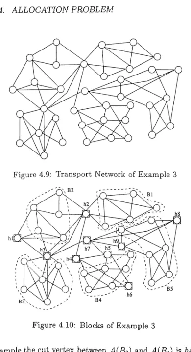
4.9 Transport Network of Example 3 53
4.10 Blocks of Example 3 53
4.11 Block Graph of Example 3 ... xii
3.1 Core Storage Requirement of the Linearizations of (QP) 29
3.2 Computational Performance of the Linearizations 31
•5.1 Computational Performance of the Linearizations of (p-HCl) . . 61
5.2 Summarized Information of the Linearizations for p-hub Center 64
5.3 CPU Times for (LinNew)... 65
5.4 Bound Values Used for Test Problem s... 67
5.5 Computational Performance of the Linearizations of (HC-1) 68
5.6 CPU times for (C-LinNew)... 70
6.1 CPU Times for Minmaxlatest with CAB2 83
6.2 CPU Times for Minmaxlatest with CABl 83
6.3 CPU Time Comparison of the Best Models 84
C hapter 1
Introduction
This thesis is on modeling and analysis of issues on hub location problems. The generic hub location problem can be stated as follows: There are n demand nodes, of any kind, each of which generates and/or absorbs demands. Exam ples include cities with passenger or cargo flows between cities, and computers with flow of data packets/messages in between. The main problem involves determining the locations of hubs and the allocation of demand nodes to hubs so as to carry the total traffic from origins to destinations via hubs to mini mize a cost function. The hubs are consolidation and dissemination centers. Flows from the same origin with different destinations are consolidated on their route to a hub facility and are combined with the flows with different origins but same destinations. Thus, hubs replace direct flows with indirect ones.
The process of consolidating and disseminating flows is referred to as ‘hubbing’ in the literature. Hub location is a rather new research area which started with a quadratic integer programming (IP) formulation of O’Kelly (1987). Since then, the literature is focused on developing ‘good’ linearizations for the O’Kelly’s model and some heuristics. However, real world applications require the consideration of different phenomena which have not been covered in the original model. Thus, the literature suffers from lack of different mod eling issues. In this thesis, we analyze the problem structure of real world
applications to identify their requirements. The analysis of cargo delivery sys tems (which is an application area of hub location problems) leads to a different problem that we call the Latest Arrival Hub Location problem. Another issue that deserves attention is on the modeling and analysis of the hub location problem under different performance criteria, e.g. minmax.
In this thesis, we first analyze the problem structure of the application areas of hub location problem : airline systems, cargo delivery systems, and telecommunications network design. We search answers to such questions as why these systems have the hub structure, what the basic assumptions or restrictions are, and under what circumstances these problems can be unified. We also identify the factors affecting the problem parameters and costs in each application area. This analysis is presented in Chapter 2.
In Chapter 3, we first identify the ‘transportation network’ aspect of the hub location problem as a distinguishing feature. We then provide a combi natorial formulation which takes into account the transportation network on which the cross traffic is carried. The existing studies in the literature on hub location have almost exclusively focused on the p-hub median problem which involves the minimization of total cost. In Chapter 3, we also present the liter ature on the p-hub median problem which involves an initial IP and different linearizations. We then provide 3 new linearizations for the initial model which are also explained in the same chapter.
Once the locations of hubs are known, the p-hub median problem turns into the hub allocation problem which is a provably difficult problem. We show in Chapter 4 that the allocation problem is NP-Hard by first proving that it is equivalent to a well known location problem, the restricted multimedian loca tion problem with mutual communication (restricted MMC). A byproduct of this analysis is a strengthened version of a previous theorem of Tamir (1993) on the complexity of the restricted MMC problem. Additionally, we identify solvable cases of the allocation problem. These cases are in two categories: the ones utilizing the structure of the flow graph, and the ones utilizing the struc ture of the transport network. The definition and utilization of the transport
CHAPTER 1. INTRODUCTION
network in this problem area is the result of our proof of equivalence of the allocation problem with the restricted MMC. The use of a transport network leads to interesting results for the allocation problem which are also discussed in Chapter 4.
Other criteria different than the total cost criterion is essentially unstud ied in the literature. We analyze the hub location problem under the minimax criterion. The minimax criterion is traditionally used in location applications to minimize the adverse effects of worst case scenarios in providing emergency service. In hub location, even though emergency service protection does not seem to be an issue, the minimax criterion is still important from the view point of minimizing the maximum dissatisfaction of passengers in air travel and minimizing the worst case delivery time in cargo delivery systems. The latter case is particularly important for delivery of perishable or time sensitive items. In Chapter 5, we analyze the hub location problem under minimax criterion, the p-hub center problem. We first prove that this problem is NP-Hard. We then focus on different linearizations of the basic model, proposed by Campbell (1994a) as well as a new model that we propose for this problem. We study the computational performances of these models. It is known from location literature that covering problems have an inverse relationship to center prob lems. Campbell (1994a) also defines the hub covering problem as it may prove to be a useful model in solving the p-hub center problem. In Chapter 5, we also analyze the hub covering problem. Utilizing its close relation to the p-hub center problem, we first prove that it is NP-Hard. We then focus on different linearizations of the basic model proposed by Campbell as well as a new model of the problem and study their computational performances. Both in the p-hub center and hub covering problems, the computational performance of the new models that we propose is far more superior than the linearizations of the basic models in terms of both CPU times and core storage requirements. This shows that it is sometimes more important to devise a new model for a given problem than focusing solely on improvements that come from different linearizations of the basic model.
the customarily defined hub location problem is not appropriate for the require ments of the real problem, especially for overnight delivery firms. Overnight delivery firms typically require a minimax type objective. Even though the p-hub center problem has a minimax objective, it is not a realistic model for overnight delivery since it focuses solely on the travel distances from origins to destinations without paying attention to how this travel actually takes place in the real world. One particular aspect that has been overlooked is the fact that any carrier departing from a hub must wait for the arrival of all incoming units that will be loaded onto that carrier. When there are hard constraints on the maximum delivery' time, as in the case of cargo delivery, it seems necessary to pay attention to waiting times at hubs to correctly compute the maximum delivery time (Hall 1989). In chapter 6, we formulate a new model which cor rectly computes the delivery times. We call the resulting model the Latest
Arrival Hub Location model. We study various aspects of the latest arrival hub
location problem including modeling variations, computational aspects, and the analysis and interpretation of the model output, meanwhile investigating answers to various what-if type questions in the same chapter.
The last chapter is a short summary of the thesis and highlights our contributions to the existing literature.
C hapter 2
R u bbing in R eal Life
In this chapter, we analyze the structure of three real world applications in which hubbing is most often encountered.
2.1
Airline System s
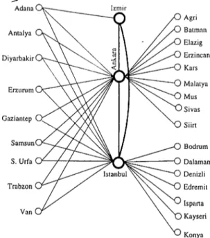
Consider an airline company which gives flight services between pairs of, say, n cities. It is possible that there will be cross-traffic between every city pair. -A. crude approach to provide the required flight services between the city pairs is to assign a direct flight between each pair of cities. This would result in ^2) flight segments which results in a highly complex and expensive network structure (Yu 1998). For example, Turkish Airlines (THY) gives, flight service in Turkey between 29 cities. If THY assigns a direct flight between each pair of cities, it would end up with 406 flights segments! However, THY provides the required service with only 38 segments using the hub structure shown in Figure 2.1.
Notice that instead of providing direct flights between every city pair, all flights are consolidated at 3 cities: Ankara, Istanbul, and Izmir. For example, any passenger flying from Ağrı to Edremit needs to follow the following route:
Figure 2.1; Segment Structure of Turkish Airlines
Ağrı — > Ankara — > Istanbul — y Edremit
Toh and Higgins (1985) analyze the economical profitability of hubs in airline systems. They classify the advantages of hubbing in two categories: Operational and Marketing.
• Operational:
- Hubbing allows indirect connections between city pairs
* which cannot generate enough volume of traffic
* which are too far from each other for direct flights.
- Indirect flights lead to serving all city pairs with minimum aircraft availability
- Shorter nonstop flows allow the use of smaller aircraft with greater frequency and higher utilization rates.
- Hubbing allows smaller processing costs since maintenance, servic ing, and apron services are centralized at a hub city.
CHAPTER 2. HUBBING IN REAL LIFE
Marketing:
- Flight arrivals/departures can he synchronized to elevate passenger load factors.
- Hubbing establishes regional identification and domination as a re sult of more frequent flights.
Kanafani and Ghobrial (1985) analyze the impacts of hubbing on airport economies. The authors also provide regional air networks for Delta Airlines for 1960, 1970, and 1982. Hubbing structure has b 3gun to emerge in the United States in 1970 and it has become dominant as of 1982. Ceha and Ohta (1994) as well as Ghobrial and Kanafani (1995) analyze hubbing in airline systems. O’Kelly (1986a) is the first thorough study of this problem. After analyzing Civil Aeronautics Board Sample Survey 1970 Report of the United States Intercity Passenger Stream, the author points out that “... several air carriers operate a highly simplified sparse network organized around hubs...” .
In view i>f the summarized advant.ages of hubbing, it is clear that the network of the segment structure of airliu.· systems will be in the hub network structure; Certain nodes will be selected as hubs, and 'TOSs-traffic between the nodes will be routed via these hubs.
We now analyze the cost paraincrter in airline 33'^stems. We base our analysis on Meyer and Oster (1984) and O’Connor (1989).
The total cost is usually aggregated from two factors:
• costs of opening hubs,
• costs of assigning flights between pairs of cities.
• The opening cost at city i, f{i): Once a node is selected as a hub, then the airport corresponding to that node will be the place where most of the ‘processings’ regarding the aircrafts and passengers are done. The sum of the costs of these processes constitutes the cost f{i). They include
- Maintenance burden: overhead costs related to the upkeep and re
pair of flight equipment and other property such as the administer ing of stockrooms, the luviping of maintenance records, scheduling and servicing of maintenance operations.
- Operating costs related to * Reservations and sales. * Advertising and publici:y.
* Traffic servicing including ticketing and baggage handling. * Terminal gate and lounge facilities.
- Cost of servicing aircraft which includes the routine services such as washing the aircraft and cleaning the passenger cabin.
- Overhead costs which includes the expenses of maintaining the or ganization such as personal functions, planning and general man agement.
• Cost of assigning a flight between two cities, c{i,j), corresponds to the sum of costs which result from having a flight scheduled between cities i and j. It will incur the following types of costs:
- Fuel cost: Each flight consumes a fixed amount of fuel for taxiing, take-off and landing. The rest of the fuel consumption varies by the distance or time flown.
- Crew cost includes the salaries of aircraft crew. This cost is depen dent on the duration of the flight since people are paid according to that.
- Direct maintenance cos·:: This cost includes the cost of labor and material directly attributable to the maintenance and repair of air craft including the periodic overhauls and other flight equipment. This cost is also dependent cn the duration of the flight.
- Miscellaneous flying and Oil cost: Miscellaneous flying and oil ex penses includes the cost for other kinds of material which are needed for a flight. They are also dependent on the flight duration.
- Passenger service: This includes the cost of food and of providing cabin attendants. This cost is also dependent on the flight duration. - Landing fee: This cost is independent of the flight duration. This
fee is to be paid for every landing of an aircraft and so it is a fixed cost.
Note that all components of c{i,j) except landing fee are travel time dependent and they are customarily defined as $ per unit time costs.
CHAPTER 2. HUBBING IN REAL LIFE 9
Since the cost components are independent of the amount of traffic car ried, this will lead to a model in which the cross-traffic between origin-destination pairs is not apparent in the objective function. If that sort of a model were applied to, say, Turkish Airlines, it may ,-esult in choosing, say, Edremit, Siirt, and Trabzon as the hub cities. Making a trip by passing through Ankara may seem reasonable lor passengers, but they may question the situation if they were forced to their destination by passing through, say, Edremit. In fact, even though the costs that we have explained in c(i,j) are not defined as per passenger costs in the optimization models that seek to find the location of hubs and allocation of nodes, they are transformed into per passenger costs. The main reason for that is to reflect the marketing issue in the models. Revenue of an airline system is based on the passenger fees and the volume of traffic. This may also be a reason to incorporate per passenger costs into the models. There may be ways to transform the explained costs to the per passenger cost on each arc. For simplicity, researchers usually use the length of an arc as the cost of carrying one passenger over that arc. Since all the significant cost components of c(i,j) are dependent on tlie time of the flight duration which is directly transformable to the length of the traveled arc, taking the length as the cost seems reasonable.
2.2
Cargo D elivery System s
Consider a firm which carries cargo between n demand centers. If the firm as signs a carrier (aircraft/truck) for each demand center pair, it will require carriers and most of the carriers will not be fully utilized (Yu 1998). Thus, as in the airline case, it is again economically infeasible to give direct service be tween each demand center pair and so hubbing is encountered in cargo delivery systems.
Another factor which is utilized in the service network structure of cargo delivery firms is the usage of stopovers.
stopover
Figure 2.2; A stopover
If stopovers exists, the carrier stops at each stopover city and collects its cargo before reaching the hub. On the way back, the cargo of the stopover cities are delivered by the same carrier. Stopovers save the companies investment in carriers and also on labor and fuel and so used frequently by cargo delivery firms. Kuby and Gray (1993) give an analysis for the case of Federal Express which show that a hub network with stopovers is economically more profitable. They also point out that the cargo should arrive at its destination in 15 hours (between 5:30 p.m. and 8.30 a.rn. the next morning). Another study for cargo delivery systems is conducted by Marsten and Muller (1980). The authors analyze the case of The Flying Tiger Line which used to operate under a single hub strategy. They proposed new hubs.
The design problem of cargo delivery systems is, again, that of deciding on the locations of hub nodes and determining the route for cargo between every city,,pair depending on the locations of these hub nodes. In the delivery business service, time is more important than its cost. As pointed out by Air Cargo World Magazine, “delivery is time-sensitive rather than price-sensitive... customers are willing to pay for time ...”. Thus, the objective may be to minimize the total cost, or to minimize the maximum delivery time between
CHAPTER 2. RUBBING IN REAL LIFE 11
an origin/destination pair (especially for overnight delivery firms), depending on the firm’s strategy. So, we consider the cargo delivery firms in two categories: cost sensitive and time sensitive. We first analyze the cost parameters for the cost sensitive case. This analysis is based on O’Connor (1989). Total cost is again aggregated from two factors: cost of declaring a city as a hub, /(i), and cost of providing direct service between two nodes, c{i,j).
• The setup cost for ‘processings’ operations, f{i), includes :
— Cost of sorting and allocating. Cargo from many demand centers come to the hub at batches. Sorting and allocating these cargo according to their destinations is a major cost component.
— Cost for unloading arriving carriers and loading the leaving ones. — Cost for storing, guarding, and providing proper protection for the
waiting cargo.
— Cost for paperwork which is used to tell shippers where their cargo is, or to keep statistics.
• Cost of providing service between two nodes i and j , c(i,j), includes:
— Cost of allocating aircraft/truck.
— Fuel cost for aircraft/truck depending on the travel time. — Crew cost, which is the salary for the driver or aircraft crew.
— Direct maintenance cost of aircraft/truck. It includes both labor and equipment cost used for maintenance.
— Equipment cost, i.e. the cost of aircraft/truck depreciated to unit time of usage.
— Other miscellaneous and oil costs which are encountered by carriers in order to ‘move’.
If the objective is to minimize the maximum delivery time, then the ‘cost’ parameter is, in fact, the duration of the corresponding journey. In order to identify the factors which constitute the cost, we need to analyze
how the delivery actually takes place. We base our analysis on Sigafoos and Easson (1988). The typical overnight delivery firm picks up packages from customers at a local station by 5:30 p.m. with a promise to deliver them to their destinations by 8:30 a.m. the next morning. Each incoming package at the local station is labeled (e.g. fragile, hazardous, flammable) and assigned a bar code that includes the zip code of the destination. The processed units are loaded onto an aircraft and are delivered to the hub which serves that local station. There are two major operations at any hub: unloading the arriving aircrafts and loading the departing ones. The packages that are unloaded from arriving aircrafts are fed into a conveyor system that is equipped with manual or automatic bar code readers. The bar code readers at the feeder lines read the zip code information and route the packages to the specific area of the hub where they can be reloaded onto the correct cargo containers. The outgoing aircraft is ready to depart when all the cargo for its destination is loaded onto it. If a departing aircraft from a hub is destined to go to a nonhub city, then it is unloaded at the local station of its final destination and the unloaded packages are delivered to the consignees by 8:30 a.m. An aircraft th at goes from a hub to another hub goes through the unloading, reloading, and the associated sorting/routing operations at the second hub to have its cargo delivered to the final destination cities that are serviced from that hub.
As is evident from the above description, the delivery time from an origin г to a destination j consists of two components: flight times and the transient times spent at hubs between flights. Then ‘for a time sensitive cargo delivery firm’ the problem is to decide on the locations of hubs and the route structure for each pair of nodes so as to minimize the latest arrival time at any consignee.
2.3
C om m unication N etw ork D esign
Communications network is the general name given to networks which are in stalled to satisfy communication between ‘devices’ which ‘communicate’ (Stallings 1991). The terms ‘communication’ and ‘communicating device’ are specified
CHAPTER 2. RUBBING IN REAL LIFE 13
according to the usage area. For example, if the devices are computers and if communication is data transfer or program execution, then we have computer communication networks. On the other hand, if devices are telephones and if communication is phone-talk, then we have telephone networks. The basic structure of all communication networks is the same. Considering the fact that the number of devices which communicate is typically very large, it is clear that providing direct connection between each pair of devices is impossible. Com munication between any pair of devices is satisfied through a ‘communication network’.
There are some special devices which are used to satisfy communication needs in a communication network. Some examples from computer communica tions are: multiplexer, concentrator, router, bridge, gate, switch, hub, repeater etc. They all have different special characteristics, but their main purpose in the communication network is to allow data to pass on its way to its destina tion. Multiplexers and concentrators are used to utilize link capacities, whereas switchers are used for switching the flowing data. Bridges and routers are used for interconnecting geographically distant devices. Hubs and repeaters repeat the incoming information on their output line. Depending on the use of these special devices, the topological structure of communication networks, and the hierarchy of the network change.
The topological structure of communication networks is hierarchical. The number of hierarchy levels depends on the size (both geographical, and the number of devices) of the communication network. The lowermost layer is composed of communicating devices, e.g. computers, telephones etc., and the upper layer(s) is composed of special devices, e.g. concentrators, hubs, etc.
The topological design problem of communication networks is customar ily defined for a two-level hierarchical structure. In fact, any problem which require more than two levels of hierarchy can be analyzed by taking into ac count two levels at a time sequentially, from down up (Stallings 1991). In a two layered network, the upper layer is called the ‘backbone network’ and the lower layer is called the ‘local access network’. Topological design problem has
three phases (Gavish 1991, 1992):
• locating backbone nodes
• designing the backbone network
• designing local access network and connecting local access network to the backbone network.
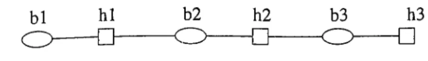
Each device in the local access network sends its message using the backbone nodes. Depending on the position of the destination device, backbone arcs may or may not be used. In order to satisfy communication between each pair, a path must exist from each device to at least one backbone node. Physical links are being established to satisfy this communication. In communication networks there are no physical carriers. Message from any device travels along the network until it reaches the destination device. In order to utilize the established links, ‘multidrop lines’ are used which means several devices are attached on a line and they use the same entrance to the backbone node. A message will flow through a link only if that link is empty at that moment. If the link is busy, the message either waits, or continues along its way by using another link (if exists).
Figure 2.3: A Multidrop Line
When installing a communication network, the set of potential locations for backbone nodes is given. The problem is to select which subset of this po tential location set will be used as backbone nodes and to determine the route structure of any communicating pair. Note that the set of potential locations for backbone nodes is not a subset of devices. This is one of the major differ ences between communication networks and airline or cargo delivery networks. In the first two application areas, hub locations are selected from among the demand centers whereas, in communication networks, hub (backbone node) locations are selected from a different set that does not include any demand
CHAPTER 2. HUBBING IN REAL LIFE 15
centers (devices). In fact, this difference can be handled by enlarging the set of demand centers by adding to it the potential hub location set. The nodes cor responding to these locations will have zero demand, i.e. the flows originating or ending at these nodes will be zero.
For communication networks there are two types of costs: communication costs and cost of delay. The delay costs include the costs that result from queuing. In the literature, there are some models which include these costs in the form of expectations based on some underlying distribution. In this thesis we mainly concentrate on the communication costs.
Communication costs are of two types: setup costs and movement costs. As discussed in Klincewicz (1998) and in Altmkemer and Yu (1992),
• setup costs of hubs, f{i), include
- investment for acquiring land for the multiplexers, concentrators etc. - all equipment costs which depend on the type of backbone node
(concentrator, switch etc.)
• arc cost, c{i,j), includes
- investment for acquiring land for the link
- material and equipment cost such as cost of fiber, repeater etc. - if the line is leased, this cost represents the fixed charge paid to the
company for using arc { i j ) .
For determining the route structure, the researchers prefer to specify the struc tures of local access and backbone networks, and analyze the problem according to that specification. Most commonly used structures are: complete, tree, star or ring structures for backbone networks and star or tree structures for local access networks.
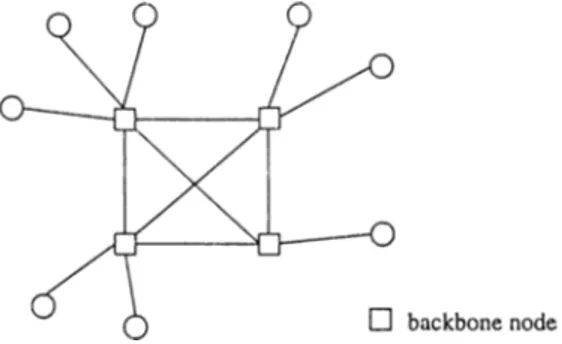
For example, if backbone network is complete and local access network is a star tree, then any device will have connection with exactly one backbone node, and data will travel along 2 or 3 links before reaching the destination.
Figure 2.4: Example of a Complete-star Topology
Problems which are in other structures can be handled by writing appro priate constraints to satisfy the required network structure in the final network. For example, Kim and Tcha (1992) analyze the case when the backbone net work is a tree and the local access network is a star tree. Lee, Ro, and Tcha (199.3) analyze ring structured backbone networks connected to a star type local access networks. Chung, Myung, and Tcha (1992) analyze the complete-star topology.
2.4
Structural Similarities and Différencies
Upto now we have identified 3 different real world application areas : airline systems, cargo delivery systems, and communication networks. The common properties of these systems are:
1) There are n demand centers and there is some sort of flow between these demand centers (people, cargo, data packets).
2) It is economically infeasible to give direct service between each pair since this would require connections which is too costly and results in a complicated network.
3) The flow between each pair is required to pass through some specific nodes which are called hubs. In airline or cargo delivery systems hubs are nodes for consolidating and disseminating flows whereas in communi cation networks they are used for switching or multiplexing data packets.
CHAPTER 2. HUBBING IN REAL LIFE 17
Besides these common properties, there are some area specific properties:
1) For cargo delivery systems there are two different problem types: cost sensitive and time sensitive. Both of them satisfy the 3 common proper ties explained above, but the design problem of the time sensitive cargo delivery systems has additional requirements.
2) Stopovers may be used in cargo delivery systems and multidrop lines may be encountered in communication networks. Such issues are not considered in airline systems.
3) In airline and cost sensitive cargo delivery systems, per passenger and per cargo costs are used which are called usage-based costs in the literature whereas in communication network design problems hub and link setup costs are considered.
The 3 common properties of the three problem areas are the basics of a problem known in the literature as the hub location problem. The hub location problem can be stated as follows: Given n demand centers with known cross traffic, and arc costs satisfying triangle inequality, determine the locations of hubs and the allocations of nonhub nodes to hubs so as to minimize the total cost. In terms of the allocation of nonhub nodes to hubs, there are two variates of the problem: the single-assignment allocation and the multi-assignment al location. In the single-assignment allocation, each node is assigned to exactly one hub whereas in the multi-assignement allocation each node can be assigned to many different hubs. A typical flow between an origin/destination pair {i,j) is then: i —> hubl —>■ hub2 —>■ j where hubl = hub2 allowed, i hubl, hub2 —)■ j, and hubl —>· hub2 are direct links . Having a direct link between
i hubl, hub2 -> j is a problem requirement (allocation phase) whereas the direct link between hubl —> hub2 is justified by the triangle inequality assumption on arc costs.
Because of this route convention of the hub location problem, we conclude that the customarily defined hub location problem has application in airline.
or cargo delivery systems and in communications network design only under certain assumptions.
Airline systems: Restricts the route between each origin destination pair to at most 3 segments on each route, stopping only at hub nodes.
Cargo delivery systems: Applicable to cost sensitive cargo delivery sys tems when stopovers are not allowed. The route restriction explained for airline systems is also valid here. For time sensitive cargo delivery sys tems, even though the basic requirements of hubbing are the same (open
p hubs, provide service to each node from hubs), there are additional
restrictions to correctly compute transport times. This special problem has not been analyzed in the literature. We propose a new model for this problem which will be explained in Chapter 6.
Communication network design: Applicable to systems with complete backbone network without any multidrop lines.
C hapter 3
T he p-H ub M edian P roblem
Most of the literature on the hub location problem is devoted to the p-hub
median problem which is the problem of locating a fixed number, p, of hubs and
finding the allocation(s) for each node based on the selected set of hubs while minimizing the total cost of travel. We provide combinatorial formulations of the p-hub median problem for both single and multi assignment cases.
3.1
Combinatorial Formulation
In the literature, the p-hub median problem is generally posed by its integer programming formulations. We first give a combinatorial formulation which is more compact and provides additional insights.
Let G = {N', E) be a connected transportation network with node set
N' — ( 1, ...,n'} and arc set E. Without loss of generality, we assume that the
nodes 1,..., n are the demand centers each of which generates and/or absorbs a positive flow from the rest of the nodes. The remaining nodes n -f-1, ...,n' are intersection points of the transport network, and neither generate nor absorb a flow, but act as transshipment points which allow the passage of flows. Let N = {1,..., n} and refer to this set as the demand set. The arc set E is composed of
the links of the transportation network. For a surface transportation system, these arcs are the road segments whereas, for air transport, the arcs correspond to nonstop flight routes. Associated with each arc (i, j) G is a weight dij > 0 which represents the cost of carrying a unit flow between its endpoints. In most cases, we may interpret this cost to be the physical distance between the endpoints of the arc. The length of a path in G is the sum of the weights of its edges. For each pair of nodes i , j G N', let Cij be the length of a shortest path connecting i and j. Note that, under the assumption of a connected network,
dj is always finite even if {i,j) ^ E. Note also that, 0 < dj < dij^i, j G N ', d j = 0 iff i = j , d j = Cji and dj + Cjk > Cik^iG^k. Let Wij denote the
flow from node i to node j with Wij or Wji > 0 for i , j G N and Wij = 0 otherwise. We define the cost network to be the auxiliary graph K = {N, A) with node set N and undirected arc set A = {{i,j) ' i , j ^ N}. Assign the weight Cij to each arc (i,j) S A. Note that the cost network is a complete graph on n nodes. In order to incorporate economies of scale resulting from the increased traffic between the hub nodes, the least cost of travel between the hub nodes is discounted by a factor a (0 < a < 1). Hence, the cost of carrying unit flow between two hub nodes k and r is ackr- The p-hub median problem can be defined using the transport network, G, or the cost network,
K. Most of the models in the literature do not differentiate between these two
networks and define the problem with respect to a ‘cost matrix’. However, how the entries of the cost matrix are defined is not very clear. In the papers that we are aware of in the literature, the problem is posed on a complete graph whose arc costs satisfy the triangle inequality. This graph corresponds to our cost network. The arc costs of the cost network, K, are induced by the shortest path lengths of an underlying transportation network, G. We prefer to make a distinction between these two networks because the structure of the transportation network has a role in determining the difficulty of the problem. For example, as will be proved in the sequel, the allocation problem is NP-Hard for p = 3 even if the transport network is a star tree whereas it is polynomially solvable for general p if the transport network is a path. The transportation network aspect of this problem is first distinguished by Kara and Tansel (1997).
CHAPTER 3. TFIE P-HUB MEDIAN PROBLEM 21
The p-hub median problem is to select a subset H = { h i , h p } of N' and allocate the rest of the demand nodes to the hub nodes hi,..., hp. As discussed in Chapter 2, H C N in airline or cargo delivery systems, and H C N' — N in communication network design. Because our focus is primarily on airline or cargo delivery systems, we follow the customary convention in the literature and assume that the hubs are selected from among the demand centers; that is, H C N .
Under the single assignment restriction, all the incoming and outgoing traffic of a node passes through the same hub. Define a{i) G if to be the hub to which nod(; i is assigned. Then the cost of carrying a unit flow from i to j is :
C a { i ) + 0: ^a(i)a(j) + ^a{j) j (^ ) '
The single assignment p-hub median problem is, then:
min min ^ Wij{Cia{i)+aCaii)aU)+Caij)j) (2)
\H\=P CeN
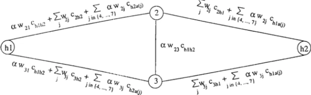
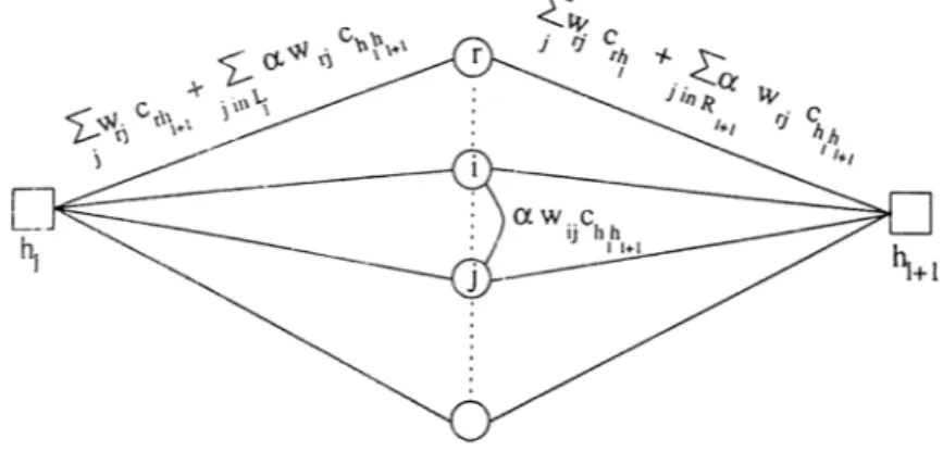
For the multiple allocation case, once the hubs are fixed, the optimal allocations of nodes can be found directly by taking into account each pair of demand nodes separately (under the assumption that the arcs are uncapaci tated). The allocation for the pair (i,j) is determined by solving:
min (cih,+ocCh,h2 + Ch2j) (3)
/11
For a fixed value of i, the result of the minimization in (3) for different values of j may cause demand center i to be allocated to different hubs. In fact, it is possible for a demand center to be allocated to all of the hubs. The multiple assignment p-hub median problem is then :
min X) Wij min {ci/n -f ach^ + <^/127} (4)
HCN, \H\=P
3.2
Literature on Hub Location Problem s
The hub location problem is first posed by O’Kelly (1986a) in which the author gives real world examples which operate under one-hub or two-hub strategies. O’Kelly points out the fact that ^2) segment requirements would drop to (n—1) if hubbing exists. Later, O’Kelly (1986b) analyzes the cost terms in a hub network and identifies the quadratic structure in hubbing. O’Kelly (1987) presents the first model of this problem which happens to be a binary program with a quadratic objective function. He considers the case with single allocation and provides the following quadratic integer programming formulation, (QP), which is later considered to be the basic model for hub location problems in the literature.
Let Xjk be a zero/one variable which takes on the value 1 if node j is assigned to hub k and 0 otherwise. Note that Xkk = 1 means there is a hub at node k and Xkk = 0 means there is no hub at node k. With the parame ters N,Wij,Cij,p, and a as defined in Section 3.1, the formulation provided by O’Kelly (1987) is :
(QP) min ^ikXik A ^^kmXikXjm T ^2 ^jmXjm} k m S.t E-Yi-k X i k^ik Xik = 1 V i e iV (5) = P (6) < Xkk V z, A: e N (7) G {0,1} y i , k e N (8)
Constraints (5) and (8) ensure that each node is assigned to exactly one hub whereas constraint (7) allows assignments to hub nodes only. The restriction on the number of hubs being p is satisfied by constraint (6). This model is linearized by many other researchers. Initial linearizations of Aykm (1995a), Campbell (1996), and Skorin-Kapov et al. (1996) are based on defining four indexed variables, namely Xijkm to replace the product terms XikXjm- Among the three, that of Skorin-Kapov et al.’s happens to perform best in
CHAPTER 3. THE P-HUB MEDIAN PROBLEM 23
terms of solution time requirements on standard optimization tools such as CPLEX. We will analyze their model later in sections 3.3.1 and 3.3.2. The best integer programming formulation (in terms of CPU time) for the p-hub median problem is due to Ernst and Krishnamoorthy (1996), (1998a) which is a multicommodity flow based formulation and will also be analyzed in sections 3.3.1 and 3.3.2.
O’Kelly and Miller (1994) develop a categorization for hub location prob lems. They identify three criteria as a basis of their categorization.
• the structure of the connection between hub nodes
• the allocation structure (single/multi)
• the existence or nonexistance of direct connections between nonhub ori-gin/destination pairs
Note that with our formulation of the cost matrix, we do not need to make the first distinction. The standard hub location problem corresponds to a hub connection structure which is a complete graph, single allocation structure, and nonexistence of direct connections between nonhubs. Aykm (1995a) develops an integer programming formulation for both single and multiple allocations where there is a subset A of demand centers for which direct service is allowed.
Aykin (1994), Campbell (1996), Klincewicz (1991), (1992), (1996), O’Kelly (1992a), O’Kelly et al. (1994), Skorin-Kapov et al. (1994) and Ernst and Kr ishnamoorthy (1996), (1998a), (1998c) develop several heuristics for the p-hub median problem. Lower bounds for the p-hub median problem are analyzed by O’Kelly (1995) and Ernst and Krishnamoorty (1998b).
Since the literature on the hub location problem is mainly devoted to the p-hub median problem, the literature on other hub location problems are sparse and so we will discuss them here. Campbell (1994a) is the only study which discusses performance measures other than the total sum criterion. He proposes integer programming formulations for the p-hub median, p-hub cen ter, uncapacitated hub location, and hub covering problems. Among these
problems, the p-hub center and the hub covering problems have not received any attention in the literature. We analyze these problems in Chapter 5.
O’Kelly (1992b) introduces the planar p-hub median problem and Aykm (1995b) develops heuristics for this problem. Campbell (1994b) presents a survey of hub location papers.
3.3
Different Linearizations of the Basic Model
In this section, we analyze the computational performance of different lineariza tions of the basic model (QP) both for single and multi assignment cases. Apart from the linearizations of the literature, we also propose new linearizations for the single assignment case.
3.3.1 Single A llocation
In the literature, there are mainly four different linearizations for (QP); the ones provided by Aykm (1995a), Campbell (1996), Skorin-Kapov et al. (1996), and Ernst and Krishnamoorthy (1996).
The first three linearizations are similar to each other. They define
Xijkm = Atyfe * Ajm and develop integer programming models which differ in
forcing that equality linearly. Among all, the best one (in terms of CPU re quirement for CPLEX 5.0) is the one provided by Skorin-Kapov'et al. (1996). Their model is also the one whose linear programming relaxation is tightest.
CHAPTER 3. THE P-HUB MEDIAN PROBLEM 25
With Cijkm = c-ik + CiCkm + Cjm the model provided by Skorin-Kapov et al. is:
(SK) min E E E E i j C i j k r n ^ i j k m i j k TTi
S.t
^ i j k m y i , j , k E N (9) X j m 'i ^ N (10) {0,1} V i,j, k , m E N (11) (5) - (8)The constraints (9) - (11) are to satisfy that Xtjkm = 1 if and only if Xik =
Xjm = 1· The authors report that the LP relaxation of their linearization has
usually ended in all integer solutions (74 of 80 in CAB2 data test which will be explained later).
The linearization of Ernst and Krishnamoorthy (1996), on the other hand, is a different approach. They utilize a multicommodity flow structure in their model. They consider output flow of each demand center as a diflferent com modity and model the related multicommodity problem. The authors define
Zii to be the amount of flow of commodity i (flow emanating from node i) that
is routed through hubs k and 1. With Oi = E ^ p and A = E A'i model
i 3
is:
(EK) min E E { O i + Di)XikCik + E E E a C k i Z i
i k i k I
S.t.
= O i X i , - E w i j X j k ' ^ i , k e N (12)
^kl ^> 0 ' i i , k , l g N (13)
(5) - (8)
where constraint (12) is the flow balance equation.
As seen in Table 3.2, the computational performance of this model solved via CPLEX is very good. The CPU time of (EK) is even better than the CPU time required to solve the LP relaxation of (SK).
was not in existence, so we have independently developed three different lin earizations for this problem:
• The first linearization is an adaptation of the linearization of Kettani and Oral (1993) for the Quadratic Assignment Problem (QAP) to the p-hub median problem.
• The second linearization is based on a multicommodity flow structure where the flow between each pair of nodes is taken as a different com modity.
• The third one is based on a reinterpretation of the quadratic objective function.
The first linearization which is based on Kettani and Oral’s approach defines a new variable Z) CijkmA^jm 3-nd forces this equality by
j ^
appropriate lower and upper bounds. The IP model of the hub location problem linearized via this approach, (KTl), is:
(KTl) min y :E W rk ^ i h + 'iik} i k
S.t.
€ik > E E Q j k m X j r n ~ D - , X , , + D + { l - X . k ) y i , k , e N (14) j ^ > 0 (5) - (8) y i , k e N (15)where and are lower and upper bounds for the variable ei*.. The authors suggest that these bounds can be determined by using the procedure suggested by Kaufman and Broeckx (1978). This results in:
D.. = min D E CijkmX jm
j
s.t. ( 5 ) - ( 8 )
and D — max y 1 Z> Elij ic.rn.X-i
s.t.(5) - (8)
While solving the model (KTl), the calculation of the lower and upper bounds
DH- and requires solving 2rP IP’s via CPLEX. Once the D~f. and for all
CHAPTER 3. THE P-HUB MEDIAN PROBLEM 27
small. The major part of the CPU time is due to the preprocessing required to form D~i^ and values. It is possible to use different and easy to calculate methods to find correct bounds for the variable etk, but then, the bounds will not be tight enough and the solution time of (KTl) would increase. As seen in Table 3.2, the computational performance of (KTl) is not satisfactory.
In the second linearization that we propose, we interpret flow between each city pair as a different commodity. We define Zijkm to be the amount of commodity (i,j) that is routed through hubs k and m. The resulting multi- commodity model is;
(KT2) min E E ( a : +A)ATifc + E E E E C'ijkm^ijkm
i k i j k HI S.t. [ W i j + W j i ) X i k { ' W i j + W j i ) X j i ^ — X i j k m m ^ijkm ^ 0
(5) - (8)
\ f i , j , k € N (16) V i,j, k , m E: N (17)where (16) is the flow balance equation. The structure of the model (KT2) is similar to that of flow with gains model. Thus, we initially expected that the CPU time requirement of (KT2) would be better than the other linearizations. However, the linearization of Ernst and Krishnamoorthy (EK) is better than that of (KT2). The structure of (KT2) is similar to that of (SK) and the computational performance of (KT2) is competitive with that of (SK) as seen in Table 3.2.
The third linearization that we propose in this report happens to be the best linearization of the p-hub median problem in terms of core storage requirements. For that linearization, we first define
A = + OCCrk)Xir
I
Xjk (18) k '■E E (^ r T ^Ok T CkAXirXjm
k r
and Since E Xik = 1, we have ^ Zj — A
k j J I .
so the objective of the p-hub median problem can be written as E A where Z.
3
is determined by (18). Observe that the second summation operator (over k) in (18) can be replaced with a maxirnand operator since there exists exactly
one k for which Xjk = 1 for every j. Then we have:
2/j ^ ^ ^ '^ii ^ ^(Qr T ^^rk)-^ir T ^kj ^ j k '^k (19)
i r -*
Consequently, the p-hub median problem can be stated as:
min Zj
3
(KT3)' s.t. (5) - (8),(19),Z,· > 0
Note that, in (KT3)' the nonlinearity is in the constraints.
O bservation 1: Zj > Y,Wij E(ci,· + a.Crk)Xir ~ Cjk + 2ckjXjk (20) correctly linearizes the constraint (19).
Proof : There are two cases to consider depending on the value of Xjk
• Case 1: If Xjk = 1> then the right hand sides of inequalities (19) and (20) are the same. ^/.
• Case 2: If = 0, then (20) provides Zj > Y,Wij YI{cir+aCrk)Xir-Cjk
i L T
whereas (19) provides Zj > 0. For ease of computation, we define 2 auxiliary variables:
Let Lik = Z)(cjr + aCrk)Xir
r
and Sj Tf ^ij\Lik ('jk T “¿CjkXjk]
i
with Zj > Sj yk
Since Xjk = 0 in this case, due to constraint (5), there exists. ^'( k)
such that Xjk> = 1·
Then 5 / = x: Wij {Lik' + Cjk')
i
and Sj 'fS/'^ij{Lik Cjk).
i
We prove the observation by showing that the inequality provided by (20) for the case with Xjk = 0 is ineffective. For this we show that
CHAPTER 3. THE P-HUB MEDIAN PROBLEM 29
We show that Lik> + Cjk' > Ltk - Cjk V k (22) which is stronger than (21). Using triangle inequality, (22) can be rewritten as
Lik' ^jk' (^kj ^kj ^ Lik' “h Ckk' ^kj ^ . (^ ir ”i” OiCkk* ^ jk‘
r
Without loss of generality, let Xis = 1. Then we have
Lik' T ^jk' ^ ^is T ^^sk' CXCkk' ^jk ^ ^is T ^^sk ^jk — Lik ^jk'
This proves the inequality (22) which is stronger than (21). So, we have shown that Sj > S j ^ k . This means that even if (20) for Xjk = 0 case provide an incorrect constraint, that constraint is ineffective since there will be another k' for which Xjk> — 1. That is, (20) always provides a correct constraint which is tighter than any incorrect one. □.
Then a new formulation for the p-hub median problem is:
min Ç Zj
j
(KT3) s.t. ( 2 0 ),(5 )-(8 ),Zj > 0
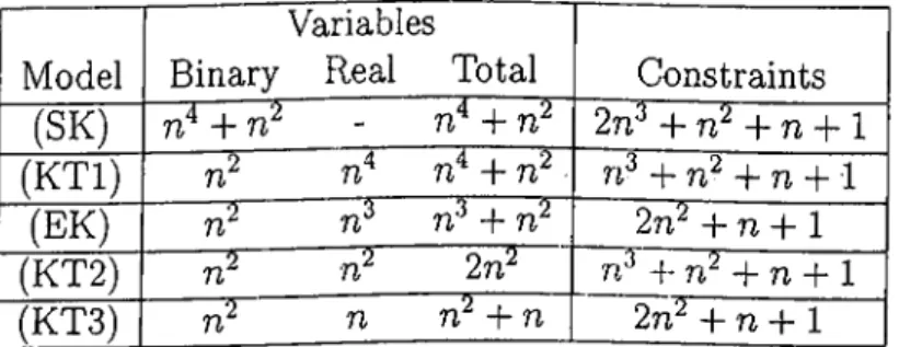
Note that in this new formulation, there are rP binary and n real variables with 2rг^ + n + 1 constraints. Table 3.1 provides the number of variables and constraints for all the linearizations.
Model Binary
Variables
Real Total Constraints
(SK) rP + rP - + rr 2n^ -f -t- n -f-1
(KTl) rP + rP n·^ + -1- n -f 1 (EK) -f rp 2n^ -f- n -t-1
(KT2) 2nP~ n'* + -\-n + l
(KT3) n rP + n 2n^ -t- n -f-1
Table 3.1: Core Storage Requirement of the Linearizations of (QP)
Note that, except for (SK), all the linearizations require rP binary vari ables. In terms of storage requirements, the best model is our third lineariza tion, (KT3).
The computational performances of all the linearizations are compared by solving the models via CPLEX 5.0 using the CAB Data set. That data set is generated from the Civil Aurenatics Board Survey of 1970 passenger data in the United States. It contains the passenger flow between 25 cities and the distance between the cities. This data set is considered as benchmark by all the researchers in hub location area and any heuristic or exact solution procedures are tested via this data set. The researchers take northwest 10, 15, 20 and 25 nodes as different sets of nodes. The number of hubs, p, is taken from the set {2, 3, 4} and the discount factor a is taken from the set {0.2, 0.4, 0.6, 0.8,1.0}. The combinations generate 4 * 3 * 5 = 60 instances. We enlarge the standard test set for p by adding the case p = 5 and compare the performance of different linearizations on the resulting 80 instances. We make a distinction about the data sets and call the standard set consisting of 60 instances CABl and call the enlarged set of 80 instances CAB2. Table 3.2 gives average and maximum CPU usage of CPLEX for each value of n with CAB2.
We have identified 5 different linearizations of the basic model, (QP). Skorin-Kapov et al. (1996) claimed that their linearization is the best among the one provided by Campbell (1996) and Aykm (1995a) in terms of solution time and quality. The common structure in all the three linearizations is that they all define Xijkm variables. The resulting models are really huge and it is nearly impossible to solve them as integer programs. Instead, the authors concentrate on LP relaxations and add integrality restrictions only when the LP solutions have noninteger variables. In the CAB2 data set, the LP relaxation of (SK) found the optimal integer solution in 74 out of 80 instances which is better than both Campbell’s and Aykm’s. However, when compared to our four indexed multicommodity flow based linearization (KT2), the performance of (KT2) is nearly 30 times faster than that of (SK) in average CPU time requirements. (KT2) gives the same performance in terms of solution quality as (SK). It finds integer solutions to the same set of 74 instances out of 80 as does (SK). The 6 instances that result in noninteger solutions have the same cost at LP optimality in both (KT2) and (SK).
CHAPTER 3. THE P-HUB MEDIAN PROBLEM 31 (EK) (KT3) n (SK) as LP 10 15 20 25 (KT2) as LP 10 15
20
25 10 1520
25 CPU Avg. Max 15.8 sec. 4.9 min. 56.9 min. 4.75 hrs. 21.8 sec. 6.1 min. 1.3 hrs. 8.56 hrs. 0.9 sec. 9.87 sec. 2 min. 9.6 min. 1.2 sec. 15.9 sec. 4 min. 19.5 min. 0.9 sec. 10 sec. 3.5 min. 28.2 min. 1.7 sec. 21 sec. 14.8 min. 4.8 hrs. 10 13.3 sec. 14.5 sec. (KTl) 15 3.6 min. 4.7 min. 20 20.05 min. 50 min. 25 1.6 hrs. 9 hrs. 10 15 20 25 5.1 sec. 1.9 min. 19.4 min 1.5 hrs. 9 sec. 4.4 min. 49.3 min. 8.83 hrs.Table 3.2: Computational Performance of the Linearizations
Ernst and Krishnamoorthy (EK) can be solved as IP in CPLEX. Both the storage requirements and solution times as IP are very low when compared with those of (SK) and (KT2) as IP ’s. In fact, the (EK) model obtains the IP solution in a few seconds even if you do not specify any starting solution. The authors also suggest a heuristic algorithm whose solution can be used as a starting solution for CPLEX. The solution quality of their heuristic is also very good. The heuristic finds the optimal solution in 59 out of 60 instances of the CABl data set.
It is also possible to solve our linearization (KTl) as IP in CPLEX. However, the solution times are higher than that of (EK). In fact, the highest portion of the solution times are due to the computation of the lower bounds
D~i^ and for each {i, k) pair. Nearly 70% of the total time is devoted to this