A GENERAL PURPOSE
ROTATION, SCALING, AND TRANSLATION
INV^ARIA^rr
PATTERN CLASSIFICATION SYSTEM
A THSaiS SUBMITTED TO
TEE DBPAE:rMBHT OF COMPUTEE EHGINB23EIHG AHB
IH F Q R M /iT iO N SCSEriCS
A im THE IH STiltJTE GF BHGiEEEEIHa
■
O F B X L K E K T ? ! V Y * · ^ C T N ‘ r U L F Z l A M E m.' O F ■.i‘.vi.:i I'i « ( · vv 4.'« F-E A ?.' h/J A -A,r·* ;"N ,^<1 *;·^ **; f’\/',t ? 6 . « T
-ys3
t 3 3 ZCorrections
Equation (3.4): Equation (3.6):
Equations (3.17) and (A. 19):
fTi^it Vj') fi^ i 4“ ^avi Uj 4" Uav) S =
R
Vj) = /r,s'(cos6» · Xi - sin6> · yj, sin6> · Xi + cos6> · ijj)
Equations (3.26) and (B.16):
sSx - - , / y Txx(cos9)^· + 2 · Txy · cos$ · .sin^ + Tyy · (.sin^)^
R x - P
Equations (3.27) and (B.17):
Q -- T!,,,г.(sin^)2 — 2 · Txy ■ cosO ■ sin^ + Tyy {cos 9)“^
R y - P
Equation (3.28):
fTRsi^ii, yj) = /(c o s 9 ■ Sx ■ Xi - sin9 ■ Sy- yj + , s in
0
* * X i ”1“ CO.S0
* Sy * y j 4 “ yav^ Equation (B.12): Equation (B.13): Sx = 6 7/--z L ^ L · f τ R { χ i , У J ) ^ χ l R x - P E! Li ^ Uf Tn( x i , y j ) - y ] Ry · PA GENERAL PURPOSE
ROTATION, SCALING, AND TRANSLATION
INVARIANT
PATTERN CLASSIFICATION SYSTEM
A THESIS SUBMITTED TO
THE DEPARTMENT OF COMPUTER ENGINEERING AND INFORMATION SCIENCE
AND THE INSTITUTE OF ENGINEERING OF BILKENT UNIVERSITY
IN PARTIAL FULFILLMENT OF THE REQUIREMENTS FOR THE DEGREE OF
MASTER OF SCIENCE
by
Gem Yiiceer
1992
Q f í
■ Ш
11 I certify that I have read this thesis and that in my opin
ion it is fully adequate, in scope and in quality, as a thesis for the degree of Master of Science.
Assoc. Prof. Kemal Oflazer (Principal Advisor)
I certify that I have read this thesis and that in my opin ion it is fully adequate, in scope and in quality, as a thesis for the degree of Master of Science.
Prof. Mehmet Bara
I certify that I have read this thesis and that in my opin ion it is fully adequate, in scope and in quality, as a thesis for the degree of Master of Science.
ssoc. Prof. Uğur Halıcı
Approved by the Institute of Engineering:
ABSTRACT
A GENERAL PURPOSE
ROTATION, SCALING, AND TRANSLATION INVARIANT
PATTERN CLASSIFICATION SYSTEM
Cem Yiiceer
M.S. in Computer Engineering and Information Science
Supervisor: Assoc. Prof. Kemal Oflazer
1992
Artificial neural networks have recently been used for pattern classification pur poses. In this work, a general purpose pattern classification system which is rotation, scaling, and, translation invariant is introduced. The system has three main blocks; a Karhunen-Loeve transformation based preprocessor, an artificial neural network based classifier, and an interpreter. Through experimentation on the English alphabet, the Japanese Katakana alphabet, and some geometric sym bols the power of the system in maintaining invariancies and performing pattern classification has been shown.
Keywords: Rotational invariancy, scaling invariancy, translational invariancy, general purpose pattern classification, artificial neural networks, Karhunen-Loeve.
ÖZET
GENEL AMAÇLI DÖNME, ÖLÇEKLENME VE ÖTELENME
DEĞİŞİMSİZ ÖRÜNTÜ SINIFLANDIRMA SİSTEMİ
>
Cem. Yüceer
Bilgisayar Mühendisliği ve Enformatik Bilimleri Bölümü
Yüksek Lisans
Tez Yöneticisi: Doçent Kemal Oflazer
1992
Yapay sinir ağlan son çalışmalarda örüntü sınıflandırma amaçları için kullanılmış tır. Bu çalışmada genel amaçlı dönme, çiçeklenme ve ötelenme değişimsiz örüntü sınıflandırma sistemi sunulmaktadır. Sistemin üç ana öbeği vardır; Karhunen- Loeve dönüşümü temelli önişlemci, yapay sinir ağı temelli sınıflandırıcı ve yo rumlayıcı. Ingiliz abecesi, Japon Katakana abecesi ve bazı geometrik simgeler üzerindeki deneysel çalışmalarla sistemin değişimsizliği sağlama ve örüntü sınıf landırma gücü gösterilmiştir.
Anahtar Kelimeler: Dönme değişimsizliği, ölçeklenme değişimsizliği, ötelenme değişimsizliği, genel amaçlı örüntü sınıflandırma, yapay sinir ağları, Karhunen- Loeve.
ACKNOWLEDGEMENT
I wish to express deep gratitude to my supervisor Assoc. Prof. Kemal Oflazer for his guidance throughout the development of this study. I am grateful to Prof. Mehmet Baray and Assoc. Prof. Uğur Halıcı for their remarks and comments on the thesis. It is a great pleasure to express my thanks to my family for providing morale support and to all my friends for their valuable discussions.
Contents
1 Introduction 1
2 Pattern Recognition and Neural Networks 4
2.1 Overview of Pattern Classification... 5
2.2 Overview of Previous Works on Pattern Classification with Neural Networks... 6
2.3 Overview of Artificial Neural N e tw o rk s ... 8
3 The Pattern Classification System 11 3.1 P R E P l: The Preprocessor with Radial Scaling Correction 13 3.1.1 The T -B lo ck ... 14
3.1.2 The S -B lo c k ... 15
3.1.3 The R -B lock ... 16
3.2 PREP2: The Preprocessor with Axial Scaling C o r r e c t io n ... 19
CO N TE N TS 11
3.3 The C la ssifie r... 21 3.4 The In te rp re te r... 23
4 Experimental Results 25
4.1 Character Recognition on the English Alphabet 26 4.2 Character Recognition on the .Japanese Katakana Alphabet 41 4.3 Classification of Geometric S y m b ols... 45
5 Conclusions 59
A Derivation of the R-Block Functions 62
List of Figures
2.1 Structure and function of a single artificial neui'on. 8 2.2 Some activation functions for the artificial neuron. 9
3.1 Block diagram of RST, the pattern classification system... 12
3.2 Block diagram of the preprocessor... 13
3.3 A sample pattern before and after the T -B lock... 15
3.4 The sample pattern before and after the S-Block... 16
3.5 The forward mapping technique and the interpolation property by the reverse mapping technique used in the S-Block... 17
3.6 The sample pattern before and after the R-Block. 19 3.7 The structure and image feeding strategy to the classifier. 22 4.1 The example patterns and corresponding class numbers for the 26 English letters... 28
LIST O F FIGURES IV
4.2 Classification results with P R E P l for letters A, B, and C rotated by 0, 60, and -60 degrees... 28 4.3 Classification results with P R E P l for letters A, B, and C scaled
by a factor of 1, 0.8, and 0.6. 29 4.4 Classification results with PR EPl for letters A, B, and C trans
lated diagonally by 0, 6, and -6 pixels... 29 4.5 Classification results with P R E P l for letters A, B, and C with 0%,
20%, and 40% noise... 30 4.6 Classification results with PR EPl for letters A, B, and C with
random translation, scaling, and rotation applied... 30 4.7 Imagel, a 512 x 512 pixel image of English text (left), the classi
fication results with PR EPl for Th = 0 (right top), and for Th = 2 (right bottom )... 31 4.8 Image2, a 512 x 512 pixel image of English text (left), the classi
fication results with PREPl for Th = 0 (right top), and for Th = 2 (right bottom )... 32 4.9 Image3, a 512 x 512 pixel image of English text (left), the classi
fication results with PR EPl for Th = 0 (right top), and for Th = 2 (right bottom )... 32 4.10 Classification results with PREP2 on rotated letters. 33 4.11 Classification results with PREP2 on scaled letters... 34 4.12 Classification results with PREP2 on translated letters. 34 4.13 Classification results with PREP2 on noisy letters... 35
4.14 Classification results with PREP2 on letters with random transla tion, scaling, and rotation applied... 35 4.15 Imagel (left), the classification results with PREP2 for Th = 0
(right top), and for Th = 2 (right bottom ). 36 4.16 Image2 (left), the classification results with PREP2 for Th = 0
(right top), and for Th = 2 (right bottom ). 36 4.17 Image3 (left), the classification results with PREP2 for Th = 0
(right top), and for Th = 2 (right bottom )... 37 4.18 Classification results, with PR EPl (left) and PREP2 (right), on
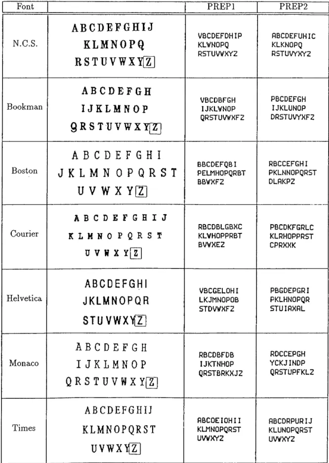
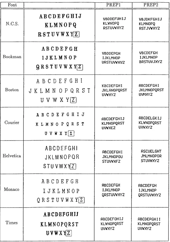
10 handcrafted English letters. 38 4.19 Classification results for English text of seven different fonts: New
Century Schoolbook, Bookman, Boston, Courier, Helvetica, Mo naco, and Times... 39 4.20 Classification results for English text of seven different fonts using
a network trained on letters of both Roman and Monaco fonts. 40 4.21 The 111 symbols of the Japanese Katakana Alphabet... 42 4.22 The 66 unique patterns and their corresponding class numbers. . 42 4.23 Classification results with PR EPl for symbols from Class 1, 2,
and 3 rotated by 0, 60, and -60 degrees. 43 4.24 Classification results with PR EPl for symbols from Class 1, 2,
and 3 scaled by a factor of 1, 0.8, and 0.6... 43 4.25 Classification results with PR EPl for symbols from Class 1, 2,
and 3 translated diagonally by 0, 6, and -6 pixels. 44
4.26 Classification results with P R E P l for symbols from Class 1, 2, and 3 with 0%, 20%, and 40% noise... 44 4.27 Classification results with PR EPl for symbols from Class 1, 2,
and 3 with random translation, scaling, and rotation applied. 45 4.28 Image4, a 512 x 512 pixel image of Japanese text (left) and the
classification result with P R E P l (right)... 46 4.29 The patterns and class numbers for the five main geometric sym
bols; circular, cross, line, square-like, and triangular. 46 4.30 Cla.ssification results with PR EPl for geometric symbols rotated
by 0, 60, and -60 degrees. 47 4.31 Classification results with PR EPl for geometric symbols scaled by
a factor of 1, 0.8, and 0.6... 48 4.32 Classification results with P R E P l for geometric symbols translated
diagonally by 0, 6, and -6 pixels. 49 4.33 Classification results with P R E P l for geometric symbols with 0%,
20%, and 40% noise... 50 4.34 Classification results with P R E P l for geometric symbols with ran
dom translation, scaling, and rotation applied. 51 4.35 Classification results with PREP2 for rotated geometric symbols. 52 4.36 Classification results with PREP2 for scaled geometric symbols. . 53 4.37 Classification results with PREP2 for translated geometric sym
bols... 54
LIST OF FIGURES vn
4.38 Classification results with PREP2 for noisy geometric symbols. 55 4.39 Classification results with PREP2 for geometric symbols with ran
dom translation, scaling, and rotation applied. 56 4.40 Classification results, with PR EPl (left) and PREP2 (right), on
patterns formed by merging two geometric symbols. 57 4.41 Classification results, with PREPl (left) and PREP2 (right), on
List of Tables
4.1 Number of training epochs and success ratios for some network configurations... 26 4.2 Performance results for English text of seven different fonts. . . . 41
Chapter 1
Introduction
The recent interest in artificial neural networks, machine learning, and parallel computation has led to renewed research in the area of pattern recognition. Pat tern recognition aims to extract information about the image and/or classify its contents. Systems having pattern recognition ability have many possible appli cations in a wide variety of areas, from simple object existence checks, through identity verification, to robot guidance in space exploration. Pattern classifica tion, a subfield of pattern recognition, is concerned with determining whether the pattern in an input image belongs to one of the predefined classes. Early pattern classification research performed in ’60s and ’ 70s focused on asymptotic prop erties of classifiers, on demonstrating convergence of density estimators, and on providing bounds for error rates. Many researchers studied parametric Bayesian classifiers where the form of input distributions is assumed to be known and parameters of distributions are estimated using techniques that require simulta neous access to all training data. These classifiers, especially those that assume Gaussian distributions, are still the most widely used since they are simple and are clearly described in a number of textbooks [5, 7]. However, the thrust of recent research has changed. More attention is being paid to practical issues as pattern classification techniques are being applied to speech, vision, robotics.
and artificial intelligence applications where real-time response with complex real world data is necessary. In all cases, pattern classification systems should be able to learn while or before performing, and make decisions depending on the recog nition result.
C H A P T E R 1. IN T R O D U C T IO N 2
Developing pattern recognition systems is usually a two-stage process. First, the designer should carefully examine the characteristics of the pattern environ ment. This involves lengthy experimentation. The result is a set of features chosen to represent the original input image. Second, the designer should choose from a variety of techniques to classify the pattern which is now in featural repre sentation. The stage of feature determination and extraction strictly determines the success of the system, since from thereon the image is represented by this featural form. Therefore, it is highly desired that the classification system itself should extract the necessary features to differentiate the example patterns that represent each class. In other words, the system should be automated to work by itself and should not depend on the human designer’s success in defining the features. Further, these features should be chosen such that they should tolerate the differentiation between the patterns in the same class. The system should also have the ability to perform the classification in a rotation, scaling, and trans lation invariant manner. This effect is typical when the scanning device, suppose a camera, changes its orientation or distance from the specimen. Hence the im age fed to the system may contain a pattern that is rotated, scaled, or translated compared to its original form when it was first presented to the system. For such a case, either the system should employ features that are invariant to such transformations or there should be a preprocessor to maintain the rotational, scaling, and translational invariancy. Even for a limited system designed for clas sifying only a determined type of patterns - an optical character classifier, or an identity verifier - it is hard to find features that extract useful information while maintaining the mentioned invariancies. The problem will be impractical if such a system is intended for general purpose classification, or to say it is aimed to classify any type of patterns.
The scope of this work was to develop a general purpose pattern classification system which is rotation, scaling, and translation invariant. In order to differen tiate any type of patterns, a neural network based system has been developed to automaticly select the necessary features, provided that some number of exam ple patterns from each class are supplied. Artificial neural networks have been chosen for the feature extraction and class determination process for their widely applied learning behaviors [1, 3, 4, 8, 12, 16]. The rotational, scaling, and trans lational invariancies has been maintained by a newly developed Karhunen-Loeve transformation based preprocessor.
C H A P T E R 1. IN T R O D U C T IO N 3
The text is organized as follows: Chapter 2 has three subsections. The first is on the pattern classification problem. The second overviews the previous re search on classifying patterns using artificial neural networks. The last subsection supplies basic information on artificial neural networks. Chapter 3 describes the proposed pattern classification system. The three main blocks - preprocessor, classifier, and interpreter - are defined. The preprocessor is further divided into three subblocks, called T-Block, S-Block, and R-Block. The definitions are clari fied with mathematical formulations. Chapter 4 gives the experimental results on three different pattern classification problems, the English alphabet, the Japanese Katakana alphabet, and five main geometric symbols. The conclusions in Chap ter 5 are followed by two appendices including the mathematical derivations of the two group of formulae given in the text.
Chapter 2
Pattern Recognition and Neural
Networks
Pattern recognition deals with the identification or interpretation of the pattern in an image. It aims to extract information about the image and/or classify its contents. A computer vision system must incorporate a pattern recognition capability. For some simple and frequently encountered patterns, the recognition process can be a straightforward task. However, when patterns are complex or when pattern characteristics can not be predicted beforehand then one needs a high-level system to perform pattern recognition. Problem attempted in this work is a subclass of the general pattern recognition problem. The aim is to classify the pattern in an input image according to the information that was extracted from the example patterns previously supplied to the system. Inputs are in the form of digitized binary-valued 2-D images containing the pattern to be classified. This representation of the 2-D image is defined and used throughout the text as the pixel-map form of the image.
CH APTER 2. PATTERN RECOGNITION AND NEURAL NETW ORKS 5
2.1
Overview of Pattern Classification
Pattern classification is concerned with determining whether the pattern in an input image belongs to one of the predefined classes. Two pattern classification techniques are major, template matching and feature extraction. In the simplest case, template matching refers to the comparison of the pixel-map of the test pattern with a number of stored pixel-maps until an exact match or a match with tolerable error is found. It is a top-down process in the sense that the trial procedure does not depend on the test pattern in any way. On the other hand, feature extraction is the process of converting the pixel-map representation of the input image to a group of quantitative descriptors called feature values. These features are usually predefined by the designer and chosen to be independent from each other [3, 4, 12].
Pattern classification using feature extraction usually starts by detection of some limited number of features. These features are chosen to distinguish most of the previously stored patterns. If a non-acceptable result is obtained, classification continues with some other features until a unique decision is made. It is important to note that the feature extraction process which converts the input image to a set of quantitative values should preserve the discrimination information throughout and after the conversion. That is, in order to attain a high success ratio in classification features should satisfy the following two requirements [12]:
• Sm all intraclass in varian ce : Patterns with similar shapes and similar general characteristics should end up with numerically close numbers for the features. •
• L arge interclass sep a ra tion : Patterns from different classes should eval uate to features which have quite different quantitative values. In other words, the patterns from different classes should differ in one or more fea tures so that discrimination can be made.
Template matching gets both computation and memory intensive when the resolution of the stored patterns increase, or when the patterns get more com plex. In addition, template matching is sensitive to the exact orientation, size, and location of the object unless rotation, scaling, and translation invariant auto correlation techniques are used. Consider the case of complex patterns which are 2-D perspective projections of 3-D objects, the patterns will be highly effected by the orientation and position of the objects, hence some form of generalized template matching will be required. That is, the stored image should be an averaged version of a number of templates. Statistical decision theory helps in the mathematical construction of the generalized template and the recognition analysis.
The computation and memory requirements for classification with feature ex traction are less severe than template matching. In most applications, computers having moderate computing power are employed to generate the Fourier descrip tors of the perimeter lines in a silhouette of the pattern. For higher level tasks, artificial intelligence techniques would be used in analyzing the information em bedded in the skeletonized form of the patterns. The fundamental problem with feature extraction is that important information may be lost in the extensive data reduction at the feature extraction stage.
C H A P T E R 2. PA T T E R N R E C O G N ITIO N AN D N EU R AL N E T W O R K S 6
2.2
Overview of Previous Works on Pattern
Classification with Neural Networks
There are two main groups of previous works on pattern classification with ar tificial neural networks. The first group, defines a featural representation for the image. In other words, the input image is transformed to some predefined features before classification is performed - a process called feature extraction.
Examples of such work are extraction of image information using regular mo ments [20], Zernike moments [12], Fourier descriptors [15, 19, 20, 23], autore gressive models [11], image representation by circular harmonic expansion [10], syntactic pattern recognition applications [6], Karhunen-Loeve expansion [13], polar-coordinate Fourier transform [2], transforming the image to another 2-D representation [14]. Kollias et.al., in their work have transformed the input im age to another 2-D representation, called (a ,6) plane, and performed classifica tion using higher-order networks [14]. Khotanzad et.al., in their work have used Zernike moments to achieve rotational invariancy in classification [12]. They have computed some finite number of Zernike moments of the given image and performed classification on these moment values. Le Cun et.al., have first skele tonized the pattern and then scanned the whole image with a 7 x 7 window, where the window templates were designed to detect some predefined features [3]. The classification was performed on the computed values. Kirby et.al., have used the Karhunen-Loeve expansion of the input image as its featural representa tion and performed classification on the expansion [13]. Among these works, the common approach is converting the input image to some compact and transforma tion invariant form, and then classifying this representation using artificial neural networks. The transformation mentioned is functionally the process of feature extraction, since the original image is converted to a form in which classification information is easily detected. However note that, features for distinguishing letters are not same as the features for distinguishing complex patterns such as fingerprints or faces. Hence, a general pattern classifier which is capable of per forming successful classifications for large number of problems will be impractical unless the classification system is designed to extract the features itself.
C H A P T E R 2. P A T T E R N R E C O G N ITIO N AN D N EU RAL N E T W O R K S 7
Second and newly developing group prefers the features to be determined and extracted by the artificial neural network itself. Martin et.al., in their work have fed the neural network by size-normalized gray scale images [17]. They report that ‘Hke generalization performance is surprisingly insensitive to characteristics of the network architecture, as long as enough training samples are used and there
C H A P T E R 2. PA TT E R N R E C O G N IT IO N AN D N EU RAL N E T W O R K S 8
x [ l ]
Figure 2.1: Structure and function of a single artificial neuron.
is sufficient capacity to support training to high levels. ”
For the system introduced through this text, an artificial neural network has been employed to extract the essential features from the input set and to per form the classification. The system also includes a preprocessor block that maps the rotated, scaled, and translated input images to a canonical form which is then classified by the neural network. Finally, the outputs of the classifier are interpreted by the interpreter block.
2.3
Overview of Artificial Neural Networks
Artificial neural networks are computational models inspired from the structure of the brain. They are massively parallel networks comprising large number of simple processing units, called artificial neurons. Artificial neural networks con stitute an alternative knowledge representation paradigm for artificial intelligence and cognitive science. The neuron structure given in Figure 2.1 is the basic build ing block of such networks. It performs a weighted summation over its inputs, where these inputs may be the outputs of other neurons or may be external to the network. The threshold, a local value for each neuron, is added to the sum. Then
C H A P T E R 2. PA TT E R N R E C O G N ITIO N AND N EU R AL N E T W O R K S 9 y=F(S) I y=F(S) II 1 -1
Figure 2.2: Some activation functions for the artificial neuron.
an activation function - also called as the limiting or squashing function - is ap plied on the resulting sum to determine the neuron’ s output value. Widely used activation function types are various sigmoids, and hard-limiting (thresholding) functions, some of which are shown in Figure 2.2.
The weights associated with the inter-neuron connections represent the influ ence of its inputs over its output - or activation - value. Depending on the sign of the weight an input may excite or inhibit the neuron. The learning behavior of artificial neural networks are accomplished by the learning algorithms continu ously updating these weights until the given inputs produce the desired outputs. There are two main types of learning algorithms:
• S u p erv ised learning : The user should supply the desired outputs while feeding the input pattern,
• U n s u p e rv ise d learn in g : The network itself gathers the necessary infor mation from the input patterns, hence develops its own representation. There is a variety of interconnection topologies between artificial neurons. The most common one is the class of multilayer feed-forward networks, where neurons are grouped as layers and connections between neurons in subsequent layers are permitted. One end of the layered structure is named as the input layer, while the other end as output layer. The inputs are fed from the input layer and the outputs are expected from the output layer. Using artificial neural networks for pattern
C H A P T E R 2. PA TT E R N RE C O G N ITIO N AND N EU R AL N E T W O R K S 10
classification purposes has become very popular in recent years. Especially feed forward type nets are frequently applied to many recognition problems [1, 3, 4, 8, 12, 16].
Chapter 3
The Pattern Classification
System
Feed-forward type neural networks, when used as a pattern classifier, are highly sensitive to transformations like rotation, scaling, and translation. This behavior emerges from the fact that throughout the training phase the area of interest concentrates mainly on the region where the pattern lies. Hence the weights associated with the input pixels that are out of this region finally decays to zero. Since the neurons in the first layer perform a weighted summation over the values of all pixels, these null weights block the information that may arise from the corresponding pixels. Note that, a transformation of any kind may push the pattern out of this region degrading the classification performance of the network dramatically. Therefore, in order to obtain a high success ratio in classification the system should provide rotation, scaling, and translation correction before attempting to classify. Such invariancy can be achieved by a preprocessor with the following properties: •
• The preprocessor should map the transformationally distorted or noisy ver sions of a pattern to a unique and stable output pattern.
C H A P T E R 3. TH E P A T T E R N CLASSIFICATIO N SYSTEM 12
Figure 3.1: Block diagram of RST, the pattern classification system.
• The mapping algorithm should be easy to compute. That is, it should not increase the overall complexity of the recognition system. A preprocessor that is functioning much slower than the classifier and/or the interpreter would turn out to be a bottleneck increasing the classification time per pattern.
Selecting good features for relatively complex patterns, like the human face or finger prints, turns out to be impractical or even impossible [13]. The problem is more acute when there is no prior knowledge on the patterns to be classi fied. Therefore, a system to automatically extract the useful features is essential. Artificial neural networks can extract information during the training process [21]. The hidden layers and the neurons in the hidden layers detect the relevant features in the images.
RST, the pattern classification system introduced in this work has a modular structure consisting of three main blocks, a preprocessor, a classifier, and an interpreter. The blocks are cascaded in order such that the original image is first preprocessed, then classified, and finally the results are interpreted. Figure 3.1 shows the block diagram for the pattern classification system.
C H A P T E R 3. TH E P A T T E R N CLASSIFICATIO N SYSTE M 13
Figure 3.2: Block diagram of the preprocessor.
3.1
P R E P l: The Preprocessor with Radial Scal
ing Correction
Feature extraction does not take place in the preprocessor. Its function is to pro vide rotational, scaling, and translational invariancy on the input image. Both the input and the output of the preprocessor are images in pixel-map form. Certain functions are performed on the input image and the resulting modified image is generated at the output. The preprocessor has three cascaded blocks, namely R- Block, S-Block, and T-Block. The block diagram is given in Figure 3.2. R-Block is to maintain rotational invariancy, while S-Block is for scaling invariancy, and T-Block is for translational invariancy.
The order in which the blocks are cascaded is determined mainly by the func tional dependencies between these blocks. In the first implementation of the preprocessor, named P R E P l, T-Block comes first, S-Block second, and R-Block last. Since the scaling and rotation operations need a proper pivot point to func tion on, the T-Block is positioned before the two blocks. T-Block will maintain translational invariancy and the origin will be the pivot point for the scaling and rotation blocks. Further, placing S-Block in front of the R-Block will bring the following two advantages:
S-Block will mostly prevent the pattern from flowing out of the image by a rotation operation. Consider an image containing a bone pattern where the bone diagonally extends between the corner points. Since our grid is of rectangular type, not a circular grid, the two ends of this pattern will
C H A P T E R 3. TH E PA TT E R N CLASSIFICATIO N SYSTE M 14
flow out of the image after a rotation of 45 degrees. However, performing scaling correction beforehand would bring a radial boundary for the pattern decreasing the effect of the mentioned problem.
S-Block will adjust the number of pixels that are active - called on-pixels and will regulate the information flowing into the R-Block. The perfor mance of R-Block degrades when the number of on-pixels is only a small portion of the total number of pixels. Hence, performing scaling correction will enable a better performance in providing rotational invariancy.
3.1.1
The T-Block
T-block maintains translational invariancy by computing the center of gravity of the pattern and translating the image so that the center of gravity coincides with the origin. Resulting image is passed to the S-Block. The center of gravity is computed by averaging the x and y coordinates of the on-pixels, as formulated below:
Define P to be the number of on-pixels:
N N
p =
t = l i = l
Then the center of gravity, {xav^Vav)^ will be: 2 N N ^ i=l j=l N N (3.1) Va« = 4 £ £ Vi) ■ Vi P r . ^ t=lj=l (3.2) (3.3) where function f{x-,y) gives the value of the pixel at the coordinates (x ,j/). For digitized binary-valued 2-D images this function will be either 0 or 1. If x or
y, the arguments of the function, are not integers then they are rounded to the nearest integer to obtain the pixel coordinates.
C H A P T E R 3. TH E P A T T E R N CLASSIFICATIO N SYSTEM 15
\
_____
V
Figure 3.3: A sample pattern before and after the T-Block. The mapping function for the translation invariant image is:
f(,^i Vj Vav) (3.4)
Function /t(·) is similar to / ( · ) except that it is for the output image of the T-Block which is translation invariant. Figure 3.3 shows the function of the T-Block on a sample patteni.
3.1.2 The S-Block
S-Block maintains scaling invariancy by scaling the image so that the average radius for the on-pixels is equal to one-fourth of the grid size. The term radius
for a pixel is defined to be the length of the straight line connecting the pixel and the origin. The scaling process will bring a radial boundary to the pattern in the image while adjusting the number of on-pixels. It thus disables any possible pattern deformation caused by rotation and regulates the information flowing into the R-Block. The average radius is computed as:
„ V ‘ ,---T ■ \/^? + y] (3-5) and the scale factor, s, is given by:
R
s = (3.6)
C H A P T E R 3. TH E PA T T E R N CLASSIFICATIO N SYSTEM 16
\ V
Figure 3.4: The sample pattern before and after the S-Block. The mapping function for the scaling invariant image is:
h s (i i,V i) = h ( s - x i , s · yj) (3.7) Function fTs{·) is similar to /t(·) except that it is for the output image of the
S-Block which is scaling invariant. Figure 3.4 shows the function of the S-Block on the sample image processed by the T-Block.
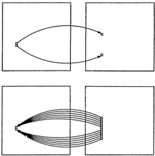
Equation 3.7, the mapping function for the S-Block, embeds the nice interpo lation property. In this equation, the pixels of the output image are mapped back to their corresponding pixels in the input image. This is called reverse mapping
and brings the interpolation property. Consider a case where the forward map ping technique is used, and two on-pixels that are adjacent in the input image are mapped to two apart pixels in the output image. There would be a disconnection between these on-pixels in the output image. However, using reverse mapping
both the apart pixels and the pixels between them are mapped back to one of the original pixels, thus maintaining the connectivity of the pattern. A scetch illustrating this discussion is given in Figure 3.5.
3.1.3
The R-Block
R-block maintains rotational invariancy by rotating the image so that the direc tion given by R-Block function coincides with the x-axis. The R-Block function
C H A P T E R 3. TH E PA TT E R N CLASSIFICATIO N SYSTEM 17
Figure 3.5; The forward mapping technique and the interpolation property by the reverse mapping technique used in the S-Block.
The derivation of the function is based on the Karhunen-Loeve transformation which has been referred in some applications [9, 13, 16]. The transformation states: Given a set of vectors, the eigenvector that corresponds to the greatest eigenvalue of the covariance matrix calculated from the set of vectors, points in the direction of maximum variance [9, 13]. This property can be used to maintain rotational invariancy since detection of the maximum variance direction will also reveal the rotation angle. A general solution for any size of vectors would be impractical. However, for 2-D vectors formed by the x and y coordinates of the on-pixels the eigenvalues are easy to compute and a formula for the eigenvector corresponding to the greatest eigenvalue can be derived from the 2 by 2 covari ance matrix. Hence, from the above discussions, the rotation parameters can be derived as: Define: rrix rUy E fe. E U f T s U , y j ) f ^ , U N N ^ ^ f T s { x i , y j ) Vi (3.8)
C H A P T E R 3. TH E PA TT E R N CLASSIFICATIO N SYSTE M 18 N N - P = E E f T s { x i , V j ) i = l j = l
(3.9)
r.x = E i ; / T s ( x , . , ! / i ) . x ? T „ = - £ i 2 f r s ( x i , y i ) - y ] (3.10) 1=1 j=l i=l j=l N N frsix i, Vj) · Xi ■ Vj (3-11) t=l j=lThe covariance matrix defined as:
T
C =
can be simplified to: (7 =
1
X y m. X y m.(3.12)
■1 N N X{ Xi T\ TUx TUx y2 ^« = i Y : j = i f T s { x i , y j ) i ^ i j = i . y j . . y j .J
. ^ y . . ^ y .(3.13)
Since translational invariancy has been maintained, the averages rtix and rUy are zero. Furthermore, the averaging term in front of the matrix can be eliminated since it does not change the direction of the eigenvectors. Therefore the covariance matrix comes out as:
C = T T T T -L xy J. yy
(3.14)
Finally (detailed derivation is given in Appendix A), the sine and cosine of the rotation angle come out as:
i'^yy ~ '^xx) T “ Txx)"^ + 4 · T^y
sin 6 —
2· \j{'^yy Txx)'^ + 4 · + {Tyy Ta;a;)j {Tyy Txx)"^ + 4 ' T^y
(3.15)
COSe =
2 - Zxy
\/{'^yy ~ TxxY + i-T^y + {Tyy - Tix)] ^{Tyy - TxxY + 4 · (3.16) The mapping function for the rotation invariant image is:
C H A P T E R 3. TH E PA T T E R N CLASSIFICATIO N SYSTE M 19
Figure 3.6: The sample pattern before and after the R-Block.
Function fTSR(') is similar to /t s(·) except that it is for the output image of the R-Block which is rotation invariant. Figure 3.6 shows the function of the R-Block on the sample pattern processed by the S-Block.
3.2
PREP2: The Preprocessor with Axial Scal
ing Correction
P R E P l, the preprocessor introduced in the previous section, performs radial scal ing correction. That is, PR EPl uses the same scaling factor along all directions. A different approach would be using different scaling factors along different axes. This type of scaling correction will uniquely map patterns regardless if they are thinner, thicker, shorter, or taller than their original forms when they were first presented. Hence the preprocessor with axial scaling correction, named PREP2, is developed after this approach. PREP2 has two main differences from the pre vious version: •
• The main blocks are reordered, such that T-Block is first, R-Block is second, and S-Block is last.
C H A P T E R 3. TH E PA T T E R N CLASSIFICATIO N SYSTEM 20
In order to maintain rotational, scaling, and translational invariancy PREP2 com putes the corresponding values as (detailed derivation is given in Appendix B):
N N P = t = l i = l
1
N N Xn 1=1 j = l N N 2/ot. = -H IZ X ] Vi) · Vj t = l i = l ( N N \ Pyy = Vj) ■ j - P -y. (3.18) (3.19) (3.20) (3.21) (3.22) (3.23) sin 0 = ( N N \ ^353 yi) ' ' y ^ ' ^ 0,v*
V a v( T , y - T , , )
+ ^(T„ -
+ 4 ■ Jg,
^ 2 · [ , / ( T „ - T,„Y + 4.72^ + {T „ - r , . ) ] + 4 ■ (3.24) COSÖ = 2 - T ly y/2 ■ y { T „ - r . , 7 + 4 ■ T l + (T „ - r „ ) ] ,/ (T „ - + 4 ■ T l ___________________________________ (3.25) R x - P *5 — 5y =Tj;j;(cos Oy -1- 2 · ’ COS 0 ' sin 9 -f ryj,(sin Ö)^
I p
T
p(3.26) (3.27) Tra;(sin 0)2 — 2 · Ti;y · cos 6 · sin 6 -f Tyy (cOS o y
where Sx and Sy are the scaling factors, and Rx and Ry are the desired deviation values along the corresponding axes. Rx and Ry are equal to the grid size.
The mapping function for the preprocessor with axial scaling correction is:
ItRsİ^İ, Vi) = f{Sx · (cos 0 ■ {Xi - Xav) + sin0· (t/j - J/av)) ,
C H A P T E R 3. TH E PA TT E R N CLASSIFICATIO N SYSTEM 21
Function fTRs{·) is similar to / ( · ) except that it is for the output image of PREP2 which is rotation, scaling, and translation invariant. There is a one step mapping from the original image function to the preprocessor output function. Note that, for PR EPl the complete mapping function could be obtained only after two passes over the original image. However, for PREP2 the whole mapping function can be computed after a single pass over the original image.
3.3
The Classifier
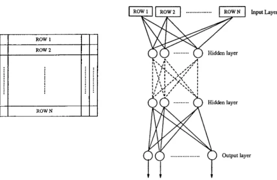
The current implementation of the system employs a multilayer feed-forward network for the classifier block. Such a network has a layered structure and only connections between neurons at subsequent layers are permitted. The training algorithm is the widely used backpropagation algorithm [21]. Since the input is an image in pixel-map form, the number of nodes in the input layer is fixed and equal to the number of pixels. Further, since the output neurons are organized such that each node represents a class, the number of output neurons is also fixed. Hence, given the input and output layer size one should decide on the number of hidden layers and the number of neurons in each hidden layer as well as the learning rate. In fact, this choice of network size is as critical as the choice of the learning rate. The decision depends on the type of the problem dealt with, and on the size and variety of the example patterns. There are two useful rules to have in mind:
• One should choose the network large enough so that the neurons can develop features to distinguish the patterns belonging to different classes, while as compact as possible to avoid memorization of the example patterns, • • One should choose the learning rate small if two or more of the example
C H A P T E R 3. TH E PA TT E R N CLASSIFICATIO N SYSTE M 22
ROW 1 ROW 2
ROWN
Figure 3.7: The structure and image feeding strategy to the classifier. The general structure of the neural network classifier is given in Figure 3.7. The output of the preprocessor, which is an image in pixel-map form, is converted to a linear array by cascading the rows of the image from the top row to the bottom row. The content of each array entry is the initial input value of the corresponding input node.
The classifier has two phases:
1. T h e tra in in g phase : The preprocessed forms of the images containing the sample patterns from each class are fed to the network, while the desired output patterns are supplied to the output neurons. The artificial neural network learns to produce the desired outputs when the sample inputs are given to the system.
2. T h e classification phase : There is no learning in the classification phase, instead the network only runs through forward passes mapping preprocessed images to output patterns. The artificial neural network is initialized with
C H A P T E R 3. TH E PA TT E R N CLASSIFICATIO N SYSTEM 23
the weights obtained at the training phase. The preprocessed image is fed to the classifier and activation values of the neurons in the consecutive layers are calculated towards the output layer. Finally, the output pattern, formed by the activation values of the output neurons, is calculated and the forward pass is over. The output pattern contains the classification information. These values are passed to the interpreter for the decision to be made.
3.4
The Interpreter
One of the key determinants of the system performance is the success in inter pretation of the classifier outputs. Since we have employed an artificial neural network for the classifier, the classification result will be in the form of activation values of the neurons in the output layer. In other words, the membership of the input pattern to each class will be represented by the activation value of the corresponding output neuron. A value close to 1 would be interpreted as a strong membership, while a value close to 0 would point a loose membership.
It is hard to decide on the method to be used so that none of the information that serves to distinguish the classes is ignored. The first alternative is to use a simple maximum finder block for the interpreter. However the performance would be moderate since it will always decide on one of the classes whether the class chosen is dominant on others or not. Since some input images will not contain any meaningful pattern or will contain patterns irrelevant with the previously sample patterns, a maximum finder block will fail to classify by deciding on one of the classes. Some level of thresholding can be applied to the outputs so that none of the classes is selected if none of the outputs exceeds this predetermined threshold. However this method may indicate multiple classes for certain inputs. This will be typical when two or more of the classifier’s outputs exceed the threshold. A more promising method is to report no discrimination as long as the ratio of
C H A P T E R 3. TH E PA TT E R N CLASSIFICATIO N SYSTEM 24
the maximum output to the next highest output remains under a predetermined threshold value. When the ratio exceeds the threshold, which means that the maximum output is dominant on the other outputs, the interpreter decides on the class with the maximum output. The interpreter block of the introduced pattern classification system employs the last mentioned method. If the ratio of the maximum output to the next highest output exceeds the predetermined number, the interpreter reports that a discrimination could be made and the pattern belong to the class with the maximum output. If not, then the interpreter reports that no unique discrimination could be made. This simple method performs well in the evaluation of the classifier outputs.
Chapter 4
Experimental Results
Based on the formulations described in the previous sections, a general purpose pattern classification system has been developed on Sun workstations using the graphics environment SunView [22]. The system is capable of performing rota tional, scaling, and translational transformations as well as adding noise on an input image. There are two type of inputs to the system; first, in the form of a single grid image; second, as a camera scanned raster image. It directly per forms classification on the single grid image, while for the raster image it scans and detects patterns and performs classifications thereon. The artificial neural network block uses the resulting weights of the backpropagation simulator HY PERBP developed on the iPSC/2 hypercube multicomputer [18]. Hence, in order to experiment on some new pattern classification problem the process goes on as follows: The example patterns are first preprocessed, then the preprocessed im ages are copied into iPSC/2 to be used as input patterns for the backpropagation simulation. The resulting weights are copied back to Sun machines and used in the classification system thereon.
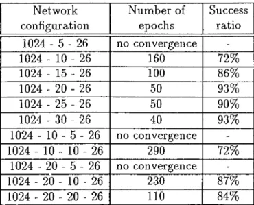
C H A P T E R 4. E X P E R IM E N T A L RESULTS 26 Network configuration 1024 - 5 - 26 1024 - 10 - 26 1024 - 15 - 26 1024 - 20 - 26 1024 - 25 - 26 1024 - 30 - 26 1024 - 10 - 5 - 26 1024 - 10 - 10 - 26 1024 - 20 - 5 - 26 1024 - 20 - 10 - 26 1024 - 20 - 20 - 26 Number of epochs no convergence 160 100 50 50 40 no convergence 290 n o c o n v e r g e n c e 230
no
Success ratio 72% 86% 93% 90% 93% 72% 87% 84%Table 4.1: Number of training epochs and success ratios for some network con figurations.
4.1
Character Recognition on the English A l
phabet
This classical problem is the classification of letters in the English alphabet. The artificial neural network chosen for classifying English alphabet is a multilayer feed-forward network. There are 1024 input nodes, each one corresponding to one of the pixels of the 32 x 32 input image. An output neuron is reserved for each pattern class, making up a total of 26 output neurons. These output neurons will compute the membership function for the pattern to the corresponding class. A value close to 1 will be interpreted as a strong membership, while a value close to 0 will point a loose membership. The number of hidden layers and the number of neurons in each hidden layer is found by trial-and-error, which is typical for most multilayer feed-forward network applications [1, 3, 4, 8, 12, 16]. Table 4.1 summaries the performances for different network configurations. The represeirtation used in network configuration is such that the first number
C H A P T E R 4. E X P E R IM E N T A L RESULTS 27
shows the number of input nodes, the last number shows the number of output neurons, and the numbers between them show the number of neurons in the corresponding hidden layer. The success ratio is the averaged percentage of the correctly classified patterns for three 512 x 512 pixel images, namely Imagel, Image2, and ImageS given in figures Figure 4.7 through Figure 4.9. Number of epochs is the number of epochs needed in the training phase until the network successfully classifies all of the example patterns. One epoc/i refers to one complete pass over all the example patterns. As seen from Table 4.1, the 1024 - 20 - 26 network has the best success ratio vs. number o f neurons figure. Hence, the network has been chosen to have 1024 input nodes, 20 neurons in the single hidden layer, and 26 neurons in the output layer.
In the training phase, the network is trained on the input example patterns until it manages to successfully classify the letters. Note that R-Block rotates the pattern until the computed orientation coincides with the x-axis. Since some pat tern and its 180 degrees rotated version will have the same orientation, R-Block will not be able to dilferentiate between them and will perform same airgle of rotation on both patterns. The resulting mappings will conserve the 180 degrees angle difference. Hence depending on its original orientation, a given pattern will be mapped to one of the two canonical patterns. These two canonical patterns will both represent the class. Therefore, the training set is formed of 52 example patterns where there are two preprocessed patterns for each class, being the pre- processed forms of the letters. The example patterns for the English letters and their corresponding classes are given in Figure 4.1.
Figure 4.2 through Figure 4.6 give the system performance on single grid im ages. The employed preprocessor is P R E P l. Images are 32 x 32 pixels. First column is the original image given to the system. Second column is the pre- processed version of the original image, and finally third column is the resulting decision. The class name and value of the corresponding output neuron are given.
C H A P T E R 4. EX P E R IM E N T A L RESULTS 28
A B C D E F G H I
1 2 3 4 5 6 7 8 9J K L M N 0 P Q R 10111213141516
1 7 18S T U V W X Y Z
19
2021 2223 24 25
26Figure 4.1: The example patterns and corresponding class numbers for the 26 English letters.
A
y r
<
Pattern is R with 0.927701 Candidate was Y with 0.021057 Discrimination ratio is 440.6 % Pattern is fl with 0.772268 Candidate was V with 0.053143 Discrimination ratio is 145.3 % Pattern is fl with 0.722949 Candidate was V with 0.029526 Discrimination ratio is 244.8 X
B oa
w
Pattern is B with 0.905775 Candidate was D with 0.030358 Discrimination ratio is 298.7 X Pattern is B with 0.894358 Candidate was D with 0.036271 Discrimination ratio is 246.6 X Pattern is B with 0.797724 Candidate was E with 0.026937 Discrimination ratio is 296.1 X
C
a
o o
o o
Pattern is C with 0.936130 Candidate was U with 0.031950 Discrimination ratio is 292.9 X Pattern is C with 0.900459 Candidate was U with 0.030605 Discrimination ratio is 294.2 X Pattern is C with 0.872540 Candidate was U with 0.032755 Discrimination ratio is 266.4 X
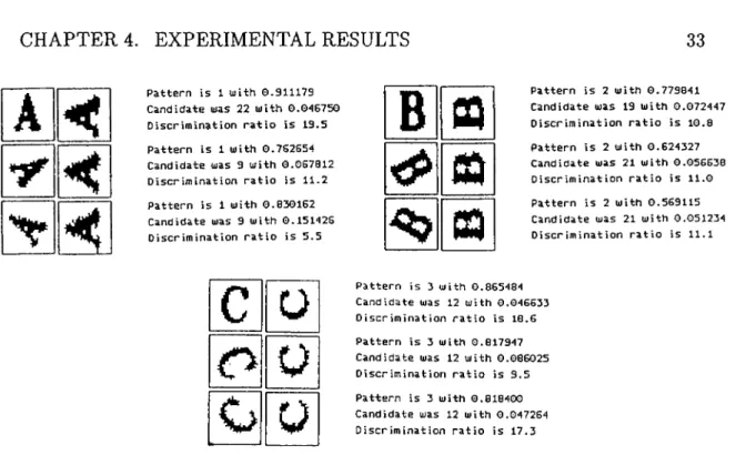
Figure 4.2: Classification results with P R E P l for letters A, B, and C rotated by 0, 60, and -60 degrees.
C H A P T E R 4. EX P E R IM E N T A L RESULTS 29
A
A
■<
A
Pattern is R with 0.927701 Candidate was Y with 0.021057 Discrimination ratio is 440.6 X Pattern is fl with 0.605121 Candidate was V with 0.040005 Discrimination ratio is 151.3 X Pattern is fi with 0.501417 Candidate was K with 0.160918 Discrimination ratio is 29.7 X
B OQ
B 03
B ep
Pattern is B with 0.917553 Candidate was D with 0.075526 Discrimination ratio is 121.5 X Pattern is B with 0.733702 Candidate was E with 0.061952 Discrimination ratio is 118.4 X Pattern is B with 0.906775 Candidate was D with 0.030358 Discrimination ratio is 298.7 X
C n
C a
C
nPattern is C with 0.936130 Candidate was U with 0.031960 Discrimination ratio is 292.9 X Pattern is C with 0.835518 Candidate was U with 0.030429 Discrimination ratio is 217.7 X Pattern is C with 0.789987 Candidate was L with 0.041864 Discrimination ratio is 180.7 X
Figure 4.3: Classification results with PREPl for letters A, B, and C scaled by a factor of 1, 0.8, and 0.6.
A <
A
i<
A
Pattern is fl with 0.927701 Candidate was Y with 0.021057 Discrimination ratio is 440.6 X Pattern is fl with 0.770125 Candidate was R with 0.041840 Discrimination ratio is 104.0 X Pattern is fl with 0.927701 Candidate was Y with 0.021057 Discrimination ratio is 440.6 XB CQ
B =Q
Bm
Pattern is B with 0.906775 Candidate was D with 0.030358 Discrimination ratio is 290.7 X Pattern is B with 0.514692 Candidate was F with 0.029781 Discrimination ratio is 172.8 X Pattern is B with 0.840754 Candidate was D with 0.099396 Discrimination ratio is 05.4 X
C
C
3C o
C o
Pattern is C with 0.936130 Candidate was U with 0.031960 Discrimination ratio is 292.9 X Pattern is C with 0.707669 Candidate was U with 0.042863 Discrimination ratio is 165.1 X Pattern is C with 0.905177 Candidate was 0 with 0.019097 Discrimination ratio is 454.9 X
Figure 4.4: Classification results with P R E P l for letters A, B, and C translated diagonally by 0, 6, and -6 pixels.
C H A P T E R 4. E X P E R IM E N T A L RESULTS 30
A
A
A
Pattern is fl with 0.927701 Candidate was Y with 0.021057 Discrimination ratio is 440.G % Pattern is R with 0.521594 Candidate was R with 0.035405 Discrimination ratio is 147.3 X Pattern is F with 0.107739 Candidate was V with 0.047904 Discrimination ratio is 22.5 X
B CQ
i
i'
m
Pattern is B with 0.79698G Candidate was E with 0.03286G Discrimination ratio is 242.5 X Pattern is B with 0.783350 Candidate was R with 0.035924 Discrimination ratio is 218.1 X Pattern is B with 0.906775 Candidate was D with 0.030358 Discrimination ratio is 298.7 X
C <T3
c o
c
Pattern is C with 0.93G130 Candidate was U with 0.031960 Discrimination ratio is 292.9 X Pattern is C with 0.877739 Candidate was 0 with 0.049185 Discrimination ratio is 178.5 X Pattern is C with 0.734900 Candidate was U with 0.024792 Discrimination ratio is 296.5 X
Figure 4.5: Classification results with PR EPl for letters A, B, and C with 0%, 20%, and 40% noise.
A
<
Pattern is fl with 0.927701 Candidate was Y with 0.021057 Discrimination ratio is 440.6 X Pattern is R with 0.283534 Candidate was V with 0.081742 Discrimination ratio is 34.7 X Pattern is R with 0.713344 Candidate was R with 0.023365 Discrimination ratio is 305.3 X
B QQ
t»
m
Pattern is B with 0.906775 Candidate was D with 0.030358 Discrimination ratio is 298.7 X Pattern is B with 0.479234 Candidate was R with 0.083784 Discrimination ratio is 57.2 X Pattern is B with 0.832631 Candidate was R with 0.035072 Discrimination ratio is 237.4 X
C
a
a
o
o o
Pattern is C with 0.936130 Candidate was U with 0.031960 Discrimination ratio is 292.9 X Pattern is C with 0.854943 Candidate was U with 0.040233 Discrimination ratio is 212.5 X Pattern is C with 0.577801 Candidate was 0 with 0.026685 Discrimination ratio is 216.5 X
Figure 4.6: ClcLSsification results with P R E P l for letters A, B, and C with random translation, scaling, and rotation applied.
C H A P T E R 4. EX P E R IM E N T A L RESULTS 31 RADIOACTIVEVASTES INANUNDERGROUND DISPOSALMAYCOME IHTOCONTACTPITH RADIOACTIVEVASTES INANUNDERGROUND DISPOSALMAYCOME IHTOCONTACTPITH
Figure 4.7; Imagel, a512 x 512 pixel image of English text (left), the claissifica- tion results with PREPl for Th = 0 (right top), and for Th = 2 (right bottom ). raster images of English text. The preprocessor is PR E P l. The images are 512 X 512 pixels. Classification is done by segmenting each letter, then position
ing the 32 X 32 grid on the letter, and performing a neural network forward pass.
Segmentation process is for boxed-discrete characters. That is, it is assumed that each single pattern can be boxed without interference from the neighboring pat terns. For a better evaluation, two separate passes over the image is performed, first when the interpreter threshold set to 0 and second the threshold set to 2. First forces the interpreter to choose one of the classes, while the second enables the interpreter to report no discrimination between the classes, represented by “ ?” in the output. The average success ratio for the given images of English text is 93%, which is considered as acceptable, for a general purpose pattern classifier. The number of floating point operations performed during a forward pass is:
m ultiplicationsadditions : 2 x (1024 x 20 + 20 x 26)
C H A P T E R 4. EX PER IM EN TAL RESULTS 32 R A D I O A C T I V E W A S T E S I N A N U N D E R G R O U N D D I S P O S A L MA Y C O ME I N T O C O N T A C T W I T H U N D E R G R O U N D W A T E R A F T E R S O M E T I M E T H U S L E A D I N G T O C 0 N T A MI N A T. I 0 N 0 P E N V I R O N M E l ( ^ RRDIORCTIVBWRSTBS INRNUNDBRGRODHD DISP05VLMRYC0VE IXTOCONTVCTWITH UNDERGROUNDWRTBR RFTERSOMETIMB THUSLERDINGTO CONTRMIHRTIOHOF BNVIRONMEhlT RRDIORCTIVBWflSTBS INRNUND7RGR07HD DISP0SVLM7YC0VE IXTOCONTVCTVITH UNDERGR0UNDV7T7R RFTERS0METI77 THUSLERDINGTO C0NTRMI7RTI0H0F BNVIR0N77NT
Figure 4.8: Image2, a 512 x 512 pixel image of English text (left), the classifica tion results with PREPl for Th = 0 (right top), and for Th = 2 (right bottom ).
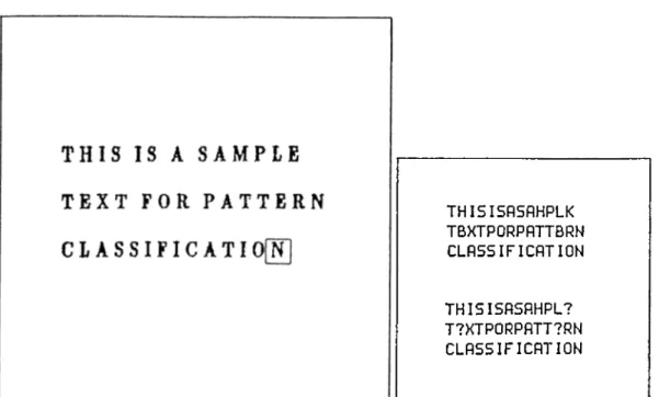
THI5ISRSRJPLE TBXTFORPRTTERN CLRSSIFICRTION THISISRSR7PLE T7XTF0RPRTTERN CLRSSIFICRTION
Figure 4.9: ImageS, a 512 x 512 pixel image of English text (left), the clcissifica-tion results with P R E P l for Th = 0 (right top), and for Th = 2 (right b ottom ).