Mutual Coupling Compensation in Receiving
Antenna Arrays
Sana Khan
Electrical Engineering Istanbul Medipol UniversityIstanbul, Turkey [email protected]
Hassan Sajjad
Electrical Engineering Istanbul Medipol UniversityIstanbul, Turkey [email protected]
Mehmet Kemal Ozdemir
Electrical Engineering Istanbul Medipol UniversityIstanbul, Turkey [email protected]
Ercument Arvas
Electrical Engineering Istanbul Medipol UniversityIstanbul, Turkey [email protected]
Abstract—Mutual coupling compensation in uniform linear and circular receiving antenna arrays of thin wire dipoles is presented. It was observed that the mutual impedance is inde-pendent of the incident angle and depends solely on the geometry of the array. By using only one measurement, decoupling matrix is computed and direction of arrival is estimated.
Index Terms—Direction of Arrival, Method of Moments, Mu-tual Coupling, Receiving Antenna Arrays, UCA, ULA.
I. INTRODUCTION
Mutual Coupling is responsible for the degradation in an-tenna array performance, both in transmitting and receiving arrays [1–4]. In direction of arrival (DoA) estimation for receiving antennas, the received voltages must be decoupled in order to estimate the incoming signal DoA. In [5], mutual impedances are calculated when the array is in receiving mode. It has been shown experimentally [6], that this method works well for decoupling with a high resolution. However, measurements are required from various incident angles in order to compute the mutual impedances. This may not be practical for experimental purposes.
In this paper, an array of thin wire dipole antennas is illu-minated by a plane wave. The received voltages are decoupled and the DoA is estimated. Examples for Uniform Linear Array (ULA) and Uniform Circular Array (UCA) are presented. Method of moments (MoM) is used to find the currents and voltages on the single mode antennas. Here, we show that the mutual impedance is constant for all angles and depends solely on the geometry of the antenna array. Furthermore, it can be calculated using only one measurement. This reduces the computation complexity and the physical labour in the experiments without degrading the accuracy of the mutual coupling compensation.
II. FORMULATION
Consider an N element array of thin wire dipoles where each element is terminated with a load ZL. The received
voltage at the antenna terminal Vi can be written as
Vi= IiZL (1)
The received voltage is the sum of two voltages, Si and Ci.
Si is the voltage induced on the ith isolated antenna and Ci
is the coupling effect from other elements. Thus (1) can be rewritten as,
Vi= Si+ Ci (2)
Ciincludes the re-radiation effects from all the other elements
of the array on the ithantenna as
Ci= Zi,1I1+ Zi,2I2+ ... + Zi,i−1Ii−1+ Zi,i+1Ii+1+ ... + Zi,NIN (3)
Here, Zi,j is the mutual impedance between elements i and j
and Ij is the current induced at the jth port, given by
Ij= Vj
ZL for j = 1, 2, ..., N. (4)
To make the presentation simple, let us assume number of elements of the array N = 4. Then, from (2), (3) and (4) we get,
V1− Z1,2 VZL2 − Z1,3 VZ3L− Z1,4 VZ4L= S1 (5) V2− Z1,2 VZL1 − Z1,2 VZ3L− Z1,3 VZ4L= S2 (6) V3− Z1,3 VZL1 − Z1,2 VZ2L− Z1,2 VZ4L= S3 (7) V4− Z1,4 VZL1 − Z1,3 VZ2L− Z1,2 VZ3L= S4 (8)
Due to the symmetry of the problems investigated, the mutual impedance matrix is Toeplitz. This property is used in the above equations. There are three unknowns, Z1,2, Z1,3 and Z1,4 which can be solved by applying least square (LS)
method to the above over-determined system for a single incident angle. Once the mutual impedances are found, the decoupling matrix can be found as follows.
1 −Z1,2 ZL − Z1,3 ZL − Z1,4 ZL −Z1,2 ZL 1 − Z1,2 ZL − Z1,3 ZL −Z1,3 ZL − Z1,2 ZL 1 − Z1,2 ZL −Z1,4 ZL − Z1,3 ZL − Z1,2 ZL 1 V1 V2 V3 V4 = S1 S2 S3 S4 (9)
III. NUMERICALEXAMPLES
In this section, examples of four-element ULA and UCA are presented. The computations are done using MoM as mentioned in[1], [7]. The mutual impedances calculated by the proposed method are compared with those of [5]. The DoA is estimated for two-coherent sources using the decoupled voltages.
978-1-7335096-0-2© 2020 ACES
A. Four-element ULA
A ULA with four dipole antennas at 2.4 GHz is considered with spacing d = 0.2λ0, length l = 0.48λ0 and l/a = 100,
where a is the radius and λ0 is the free space wavelength.
Each antenna is terminated with ZL= 50 Ω load impedance.
The array is excited by a plane wave with θ = 90◦and φ = 90◦, where θ and φ are measured from positive z and positive x directions, respectively. These angles are chosen because coupling effect is maximum for the ULA. Using MoM, we find the received voltages at each antenna terminal, which is the coupled voltage. Then, the isolated voltages are computed by considering one antenna at a time in the absence of the others. Solving (5) to (8), we find the mutual impedances which are shown in Table I. It should be noted that in the proposed method, only one measurement angle (θ, φ) was used to compute the mutual impedances, whereas in [5] at least 10 angles were required to compute the same mutual impedances. It was observed that the mutual impedances found in the proposed method are more accurate than in [5]. Since mutual impedance is independent of the angle of arrival, the decoupling matrix of the proposed method can decouple any voltage irrespective of the incident angle, whereas [5] limits itself to a fixed elevation angle. The real and imaginary mutual impedances are shown in Fig. 1, which are constant for all angles (θ, φ).
B. DoA estimation of two sources
Here, two cases for DoA estimation are discussed. In case I, the ULA was excited by two plane waves, with fixed φ = 90o and different elevation angles, θ1=45o and θ2=75o. The
un-coupled voltages were computed using the mutual impedances of Table I. The isolated, coupled and uncoupled voltages were given as an input to MUSIC algorithm [5] with forward-only spatial smoothing due to the coherent sources as plane wave. In case II, the plane waves were incident from a fixed θ = 90o but different azimuth angles φ1= 45o and φ2= 75o. As Fig. 2
shows, both of the DoAs are successfully detected.
C. Four-element UCA
The same dipole antennas are arranged in a UCA with a radius of λ0/8 and excited by the plane wave with θ = 90◦,
φ = 90◦. The coupled and isolated voltages are calculated and then the mutual impedances are computed which are compared in Table I.
TABLE I. RECEIVEDMUTUALIMPEDANCES
Comparison ULA
Z1,2 Z1,3 Z1,4
Proposed −19.26 + 11.13i 0.0675 + 15.38i 10.39 + 4.866i Ref [5] −18.47 + 10.94i 0.0263 + 15.61i 10.72 + 4.732i
UCA
Proposed −21.56 + 9.238i −14.52 + 14.12i −21.74 + 9.371i Ref [5] −21.95 + 10.62i −12.39 + 15.71i −21.95 + 10.62i
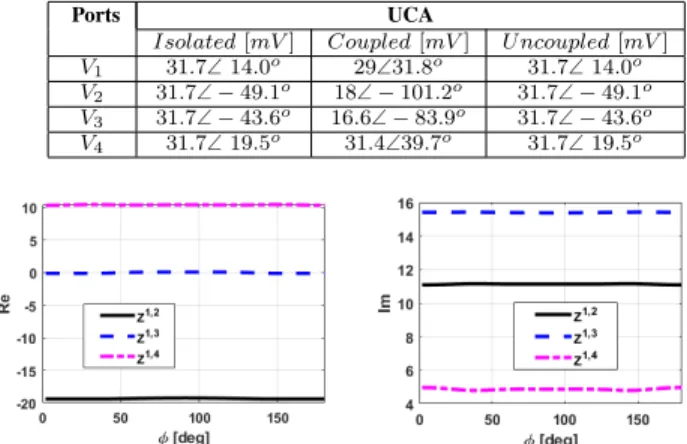
As an example, the UCA was excited by two incident plane waves with θ = 90o and φ1= 35o and φ2= 45o. The
isolated, coupled and uncoupled voltages are shown in Table II. It can be seen that mutual coupling has been successfully compensated.
TABLE II. ISOLATED,COUPLED AND UNCOUPLED VOLTAGES
Ports UCA
Isolated [mV ] Coupled [mV ] U ncoupled [mV ] V1 31.7∠ 14.0o 29∠31.8o 31.7∠ 14.0o
V2 31.7∠ − 49.1o 18∠ − 101.2o 31.7∠ − 49.1o
V3 31.7∠ − 43.6o 16.6∠ − 83.9o 31.7∠ − 43.6o
V4 31.7∠ 19.5o 31.4∠39.7o 31.7∠ 19.5o
Fig. 1. Mutual impedance (left) real and (right) imaginary for four elements ULA, for all elevation angles.
Fig. 2. Spatial spectrum of MUSIC algorithm for DoA detection of two coherent signals from. (Left): φ = 90o, θ
1= 45o, θ2= 75o. (Right): θ = 90o, φ1= 45o, φ2= 75o.
IV. CONCLUSION
Mutual coupling in receiving antenna arrays of thin wire dipoles has been compensated by using only one measurement. It was observed that the mutual impedance depends only on the geometry of the structure and is independent of the incident angle.
ACKNOWLEDGMENT
This work has been partially supported by Tubitak project 215E316.
REFERENCES
[1] S. Khan, H. Sajjad, M. K. Ozdemir and E. Arvas, “Mutual Coupling Compensation in Transmitting Arrays of Thin Wire Antennas,” ACES Journal, vol. 33, no. 11, pp. 1182-1189, Nov. 2018.
[2] M. K. Ozdemir, H. Arslan and E. Arvas, “Mutual coupling effect in mul-tiantenna wireless communication systems,” GLOBECOM ’03. IEEE Global Telecommunications Conference (IEEE Cat. No.03CH37489), San Francisco, CA, vol. 2, pp. 829-833, 2003.
[3] H. Sajjad, S. Khan and E. Arvas, “Mutual coupling reduction in array elements using EBG structures,” 2017 International Applied Computa-tional Electromagnetics Society Symposium - Italy (ACES), Florence, pp. 1-2, 2017.
[4] X. Chen, S. Zhang and Q. Li, “A Review of Mutual Coupling in MIMO Systems,” in IEEE Access, vol. 6, pp. 24706-24719, 2018.
[5] H. Lui and H. T. Hui, “Mutual coupling compensation of compact an-tenna array for direction-of-arrivals estimations,” 2010 4th International Conference on Signal Processing and Communication Systems, Gold Coast, QLD, pp. 1-10, 2010.
[6] Y. Yu, H. Lui, C. H. Niow and H. T. Hui, “Improved DOA Estima-tions Using the Receiving Mutual Impedances for Mutual Coupling Compensation: An Experimental Study,” IEEE Transactions on Wireless Communications, vol. 10, no. 7, pp. 2228-2233, July 2011.
[7] S. Khan and E. Arvas, “Compensation for the Mutual Coupling in Transmitting Antenna Arrays,” IEEE APACE, pp. 84-88, Dec. 2016.