DEVELOPMENT OF FIBER OPTIC PROBES
AND A DUAL WAVELENGTH LASER
SYSTEM FOR MEDICAL APPLICATIONS
a thesis submitted to
the graduate school of engineering and science
of bilkent university
in partial fulfillment of the requirements for
the degree of
master of science
in
material science and nanotechnology
By
Elif Uzcengiz S
¸im¸sek
January 2016
DEVELOPMENT OF FIBER OPTIC PROBES AND A DUAL WAVELENGTH LASER SYSTEM FOR MEDICAL APPLICA-TIONS
By Elif Uzcengiz S¸im¸sek January 2016
We certify that we have read this thesis and that in our opinion it is fully adequate, in scope and in quality, as a thesis for the degree of Master of Science.
B¨ulend Orta¸c(Advisor)
S¨uleyman Serdar Kozat
Sel¸cuk Akt¨urk
Approved for the Graduate School of Engineering and Science:
Levent Onural
ABSTRACT
DEVELOPMENT OF FIBER OPTIC PROBES AND A
DUAL WAVELENGTH LASER SYSTEM FOR
MEDICAL APPLICATIONS
Elif Uzcengiz S¸im¸sek
M.S. in Material Science and Nanotechnology Advisor: B¨ulend Orta¸c
January 2016
Optical fibers have been widely used in the past several decades due to their characteristics, such as laser energy transmission, low optical loss and different beam shape. These features make them advantegous for different applications in a number of fields such as telecommunication, imaging, laser cavity systems and medical applications. Fiber optic probes were developed to use optical fiber systems in medicine since they are flexible, small in diameter, easy to use and they transmit the laser energy through the target tissue of the body without any additional optical alignment. The tip geometry of the fiber optic probes can be changed so that the laser radiation is emitted with different shapes. Flat-ended, side-firing, radial, double radial and diffusing fiber optic probes, having different beam shapes, were developed by using mechanical polishing and also, CO2 laser
polishing technique was demonstrated for fining radial fiber tips for the first time throughout this study. The probes were analyzed in terms of ray tracing, Zemax modelling, fabrication and light deflection. As a result, the spatial distribution of the fabricated probes were optimized. Different beam shapes originating from each fiber optic probe can serve for specific purposes. One of them is to use the diffusing probe as a cladding light stripper (CLS) in the fiber laser cavity since it improves the beam quality of the fiber laser. On the other hand, endovenous laser ablation (EVLA) is one of the operations that flat, radial and double radial probes are preferred for ablating the varicose vein reflux, which is a common disease seen in 25% of women and 15% of men in the USA. A dual-wavelength medical laser system (980nm-1470nm), operating both at continuous wave (cw) and pulsed wave (pw), was also developed and characterized in terms of spec-trum, power and pulse duration. A whole medical laser system consisting of the home-made radial fiber optic probe and the dual-wavelength medical laser system
iv
was assembled. In conclusion, design, development and characterization of the fiber optic probes having different beam shapes were performed and two differ-ent applications, namely CLS and a dual-wavelength medical laser system, were presented.
Keywords: Fiber optic probes, cladding light strippers, dual wavelength medical laser system, endovenous laser ablation (EVLA).
¨
OZET
MED˙IKAL UYGULAMALAR ˙IC
¸ ˙IN F˙IBER OPT˙IK
PROBLAR VE ˙IK˙IL˙I DALGA BOYLU LAZER S˙ISTEM˙I
GEL˙IS
¸T˙IR˙ILMES˙I
Elif Uzcengiz S¸im¸sek
Material Science and Nanotechnology, Y¨uksek Lisans Tez Danı¸smanı: B¨ulend Orta¸c
Aralık 2015
Optik fiberler, lazer enerjisini do˘grusal olmayan bir ¸sekilde ta¸sıyabilmeleri, d¨u¸s¨uk optik kayıp ve ı¸sı˘gı farklı ¸sekillerde yayabilmeleri gibi ¨ozellikleri dolayısıyla yaygın bir ¸sekilde kullanılmaktadır. Bu avantajlı ¨ozelliklerinden dolayı teleko-munikasyon, g¨or¨unt¨uleme, lazer rezenat¨or sistemleri ve medikal uygulamalarda tercih edilmektedir. Optik fiberler, esnek bir yapıya sahip olmaları, ¸caplarının k¨u¸c¨uk olması, lazer enerjisini v¨ucut i¸cerisinde bulunan hedef dokulara rahatlıkla ula¸stırabilmeleri dolayısıyla tıbb`ı uygulamalarda kullanılmaktadır. Ayrıca, u¸c ge-ometrileri de˘gi¸stirilerek, lazer enerjisinin da˘gılımı farklı ¸sekillerde elde edilebilir. Bu ¸calı¸smada, d¨uz-u¸c, yan-atım, radyal, ¸ciftli radyal ve da˘gıtıcı u¸clu optik prob-lar mekanik zmparalama ve CO2 lazer cilalama teknikleri ile gelitirilmi¸sdir.
Geli¸stirilen problar, ı¸sın teorisi, Zemax analizleri, ¨uretilme teknikleri ve ı¸sık da˘gılım ¨ol¸c¨umleri ile incelenmi¸stir. B¨oylece, fiberlerin uzaysal da˘gılım profilleri optimize edilmi¸stir. Farklı u¸c geometrisine sahip her bir fiber prob i¸cin farklı bir uygulama alanı vardır. Da˘gıtıcı fiber u¸clarının, fiber lazer sistemlerinde kılıf ı¸sı˘gı sıyırıcısı olarak kullanılması bu alanlardan biridir. Kılıfta ilerleyen ı¸sık, kılıf ı¸sı˘gı sıyırıcı tarafından ¸cıkarılarak lazer ı¸sık kalitesi y¨ukseltilmi¸s olur. Di˘ger bir taraftan, d¨uz u¸c, radyal ve ¸ciftli radyal u¸clu problar yaygın bir hastalık olan varis tedavisinde, di˘ger bir deyi¸sle, end¨oven¨oz lazer ablasyonunda (EVLA) kul-lanılırlar. ABD’de kadınların %25’i ve erkeklerin %15’i bu hastal˘ga yakalan-maktadırlar. EVLA operasyonunda kullanılmak ¨uzere, ikili dalga boyunda, hem s¨urekli hem de atımlı dalga boyunda ¸cal¸sabilen bir lazer sistemi tasarlanm¸s; spek-trum, g¨u¸c ve atım ¨ozellikleri karakterize edilmi¸stir. Varis tedavisinde kullanılmak ¨
uzere hem radyal fiber probu hem de ikili dalga boylu lazer sistemi bir araya ge-tirilmi¸stir. Sonu¸c olarak, farklı uzaysal da˘gılıma sahip fiber optik problar tasar-lanmı¸s, geli¸stirilmi¸s ve karakterize edilmi¸stir ve iki farklı alan olan kılıf ı¸sı˘gı sıyırıcı
vi
olarak fiber lazer sisteminde; fiber prob olarak ikili dalga boyuna sahip bir medikal lazer sisteminde kullanılmı¸stır.
Anahtar s¨ozc¨ukler : Fiber optik problar, kılıf ı¸sı˘gı sıyırıcı, ikili dalgaboylu medikal lazer sistemi, endoven¨oz lazer ablasyon (EVLA).
Acknowledgement
I acknowledge that apart from my effort, the encouragement and guideness of many other people contributed to the success and existence of this study. Firstly, I would like to express my sincere gratitude to my advisor Assist. Prof. Dr. B¨ulend Orta¸c for giving me this opportunity and his endless help, support, encouragement, guideness, and supervision for this study. I also would like to thank Dr. Erol ¨Ozg¨ur and Ali Ayta¸c Seymen for giving me this opportunity to be a part of this project and their endless help.
This work is partially supported by TUBITAK under the project number of 113A055. I acknowledge support from Turkish Academy of Sciences under the TUBA-GEB˙IP program and Bilim Akademisi - The Science Academy Turkey under the BAGEP program. This work is partially supported by TUBITAK under the 1501 program, project number 3140846. I would like to express my sincere gratitude to TUBITAK for their support.
I would like to thank to our research group members for their friendship, encouragement and support. I would like to thank Canan Kur¸sung¨oz who was there for me to complete this thesis with her encouragement, support, patience, positive attitude and lovely friendship and also thank Dr. Tolga Ba˘gcı for helping and encouraging me for this work. I would like to thank Yakup Midilli for helping and guiding me for the experimental procedure in the lab. I would like to thank to Bartu S¸im¸sek as my husband, friend, group member, diving-body and the one who always cheers me up for his help for experimental work, encourage, love, and especially his deep patience. I also thank to Refik Tuzaklı for his friendship and encouregement. I want to thank to new member of our research group O. Benjamin Efunbajo for his friendship. I would like to thank to Ya˘gmur Yılmaz, who is R&D engineer at EA Teknoloji, for her endless help for the laboratory work and her contributions to our research. My special thank goes to our laboratory technician Levent Ersoy who always helps me to set experimental setup and his friendship.
viii
I would like to thank to UNAM members, friends and staff for their support and friendship. I want to thank to Gamze Toruno˘glu for her help for the AFM study.
I would like to thank to my family, my father Orhan Uzcengiz, who passed away eight years ago, my lovely mother S¸¨ukran Uzcengiz, my lovely sister Yasemin Orak and her husband Alican Orak, my mother in-law Leyla S¸im¸sek, my father in-law ¨Ozer S¸im¸sek and my little sweety sister in-law Tuana S¸im¸sek for their endless love, encourage and support.
Contents
1 Introduction 1
2 Theory of Light Guiding in a Cylindrical Waveguide 3
2.1 Ray Tracing Theory and Fundamental Concepts . . . 4
2.1.1 Snell’s Law . . . 5
2.1.2 Critical Angle . . . 5
2.1.3 Total Internal Reflection . . . 6
2.1.4 Numerical Aperture . . . 7
2.1.5 Acceptance Angle . . . 8
2.1.6 Brewster Angle . . . 9
2.1.7 Multi Mode and Single Mode Fibers . . . 10
2.2 Electromagnetic Theory for Optical Radiation . . . 11
2.2.1 Electromagnetical Waves . . . 12
CONTENTS x
2.2.3 Spatial Distribution of Modes in Cylindrical Waveguide . . 15
2.3 Types of Fibers . . . 16
2.3.1 Step Index Fiber . . . 16
2.3.2 Graded Index Fiber . . . 17
2.4 Losses in Optical Fibers . . . 17
3 Fiber Optic Probes 19 3.1 Designing a Fiber Optical System at Zemax . . . 20
3.2 Fabrication Procedure of Fiber Optic Probes . . . 21
3.2.1 Mechanical Fabrication Procedure . . . 21
3.2.2 Laser Polishing Procedure . . . 26
3.3 Radial Fiber Optical Probe . . . 28
3.3.1 Ray Tracing . . . 29
3.3.2 Zemax Modelling . . . 30
3.3.3 Fabrication and Light Deflection Measurements . . . 31
3.4 Double-Ring Radial Fiber Optical Probe . . . 37
3.4.1 Zemax Modelling . . . 38
3.4.2 Light Deflection Measurements . . . 40
3.5 Side-Firing Fiber Optic Probe . . . 41
CONTENTS xi
3.5.2 Zemax Modelling . . . 43
3.5.3 Fabrication . . . 44
3.5.4 Light Deflection Measurements . . . 45
3.6 Flat-ended Fiber Optic Probe . . . 47
3.6.1 Ray Tracing . . . 47
3.6.2 Zemax Modelling . . . 48
3.6.3 Fabrication . . . 49
3.6.4 Light Deflection Measurements . . . 49
3.7 Fabrication of Fiber Optic Connector . . . 50
3.8 Diffusing Fiber Optical Probe . . . 52
3.8.1 Fabrication . . . 52
3.8.2 High Power Laser Application: Cladding Light Strippers . 53 3.8.3 Fabrication and Characterization of Cladding Light Stripper 55 4 Fiber Optic Probes in Medical Laser Applications 62 4.1 Endovenous Laser Ablation (EVLA) . . . 62
4.1.1 Wavelength Selection for EVLA . . . 63
4.2 Test and Measurement of the Medical Laser System . . . 65
4.2.1 Spectral Analysis . . . 66
CONTENTS xii
List of Figures
2.1 Optical fiber . . . 4
2.2 Snell Law . . . 6
2.3 Total internal reflection (TIR) . . . 7
2.4 Illustration of multimode and single mode fibers . . . 11
2.5 Fiber types . . . 17
2.6 Power loss mechanisms inside fiber . . . 18
3.1 Polishing films . . . 22
3.2 SEM images of polishing films . . . 23
3.3 Optical microscope images of polished fiber end-faces . . . 24
3.4 Polishing procedure . . . 24
3.5 CO2 laser polishing setup . . . 26
3.6 Result of laser polishing of fiber end-face . . . 27
LIST OF FIGURES xiv
3.8 Zemax simulation for radial fiber . . . 31
3.9 Fabrication procedure of side-firing fiber . . . 32
3.10 SEM images of conic tip fiber surfaces . . . 33
3.11 Schematic drawing of the measurement setup and graph for light deflection of radial tip fiber . . . 34
3.12 Light deflection measurements for radial fiber . . . 35
3.13 SEM images of laser treated fiber tips . . . 36
3.14 AFM images of fiber tips polished by mechanic and laser process . 37 3.15 Deflection measurements for laser treated fiber tips . . . 37
3.16 Zemax simulation for double-ring radial fiber . . . 39
3.17 Light deflection measurements of double ring fiber . . . 40
3.18 Ray tracing analysis for side-firing fiber . . . 42
3.19 Zemax simulation for side-firing fiber . . . 44
3.20 Fabrication procedure of the side-firing fiber . . . 45
3.21 Side fire light deflection calculation . . . 46
3.22 Light deflection measurements for side-firing fiber . . . 46
3.23 Ray tracing analysis of flat-ended fiber . . . 48
3.24 Zemax simulation for flat-ended fiber . . . 48
LIST OF FIGURES xv
3.26 Light deflection measurement setup and measurement for
flat-ended fiber . . . 50
3.27 Optical fiber connector preparing procedure . . . 51
3.28 Diffusing fiber . . . 53
3.29 Fiber laser schematic . . . 54
3.30 Aim of cladding light stripper . . . 54
3.31 CLS measurement setup . . . 56
3.32 Rough CLS . . . 57
3.33 Rough and HIP coated CLS . . . 57
3.34 HIP coated CLS . . . 58
3.35 Performace of fabricated CLS . . . 58
3.36 Cascaded CLS . . . 60
3.37 CascadedCLSthermalimage . . . 61
4.1 Endovenous Laser Ablation (EVLA) . . . 63
4.2 Wavelength absorption graph prefered for EVLA . . . 64
4.3 MM fiber attenuation . . . 65
4.4 Medical laser system design . . . 66
4.5 Spectral analysis of 980nm diode . . . 67
LIST OF FIGURES xvi
4.7 Laser diode characterization setup and medical laser system . . . 68 4.8 Air cooling results of laser diodes . . . 69 4.9 Power and power stability of the diodes due to air cooling . . . . 70 4.10 Rise-time of the pulsed diodes . . . 70 4.11 Demonstration of laser pulses in the time domain . . . 71
Chapter 1
Introduction
In the past several decades, optical fibers have attracted a great attention since they transmit laser energy, with low-loss and with different beam shape [1]. They are especially used in several fields such as telecommunication, imaging, laser cav-ity systems and medical applications. In this thesis, medical application of fiber optic probes will be studied. Fiber optic probes are widely used in the clinical environment due to their various advantages. They are flexible, small in diame-ter, easy to use since they can transmit laser energy through the target tissue in the body without any additional optical alignment. Fiber optic probes emit laser radiation with different shapes by changing their tip geometry [2]. Flat-ended, side-firing, radial, double radial and diffusing fiber probes have different beam shapes which are specific to a medical application. Flat-ended, radial and double radial probes are widely used in endovenous laser ablation (EVLA) [3]. Side-firing probes are used in prostate [4], breast cancer tumor ablation [5]. Diffusing fiber probes are preferred for photodynamic theraphy [6]. The fiber optical probe con-sists of three main parts, namely optical connector, fiber and its tip. One of them is optical connector and the other part is tip geometry. An optical connector is a tool that provides that fiber plug in and out of the laser without optical alignment [7]. Fiber optical probes are easy to use, fast and user friendly thanks to optical connector. Besides the optical connector, fiber tip geometry is the significant part of the fiber optic probes since laser energy can be emitted with different shapes
by changing the fiber tip geometry. Therefore, laser energy can be transmitted through the target tissue in the body with a preferred beam shape and position. The probes that mentioned above will be investigated in terms of ray tracing analysis, Zemax modelling, fabrication and light deflection characterization. In the fabrication part, two types of polishing techniques were used. One of them is mechanical polishing which is performed by polishing machine and lapping (pol-ishing) films. This process is a time-consuming process and laborer dependent. Therefore, CO2 laser polishing, which is the second technique, will be explained
and was demonstrated in radial fiber probes after forming the fiber tip geometry by mechanical polishing for the first time. Also, a new approach of fabricating double ring radial fiber optic probe will be investigated.
The rest of this thesis includes development of a dual wavelength medical laser system mainly used for EVLA. The medical laser is working at two different wavelengths, 980nm and 1470nm, respectively. 980nm is mostly used in EVLA, however, in the recent studied it is reported that longer wavelengths are much more efficient. In order to build the medical laser system, dual wavelength diode was analyzed in terms of spectra, wavelength shift with the change in cooling temperature, power and power stability. This analysis was used to build a feed-back supported cooling system. The medical laser system can operate in both continuous wave (cw) and pulsed wave (pw) modes. Pulsed mode is provided by electronical circuit. Interval, duration, power, number of pulses, operating wavelength and mode (cw or pw) can be selected in the user interface.
Chapter 2
Theory of Light Guiding in a
Cylindrical Waveguide
Fiber Optics - Historical Background
Guiding light in a long narrow material has been studied for recent decades. Af-ter invention of lasers in 1960, transmitting information in a long distances using light became a great opportunity [8]. Light can carry the information faster than microwaves due to high optical frequencies [9]. After invention of the ruby-laser, using fiber optics for long-distance communication is stand out. Thus, the enor-mous development on the fiber optic technology has begun and still continues today [10] . The main principle of guiding light in a dielectric media is total internal reflection (TIR) with spesific conditions. The silica glass surrounded by air is used as a cylindrical waveguide. However, glass-air interface which is non-homogeneous and has discontinuous points lead to high optical loss [11]. The decibel (dB) is a logarithmic unit that implies a ratio between a level of quantity to reference. In fiber optics, dB unit is generally used for expressing the laser power. In 1966, Kao and Hockham have published an important paper stating that the necessary transimission medium conditions can be provided by silica glass based an optical fiber structure, thus, metallic and other impurities would
Figure 2.1: Schematic drawing of an optical fiber.
be eliminated. The scheme of the optical fiber structure which is composed of an inner cylinder glass core having refractive index ncore and an outer cylinder glass
having refractive index ncladding slightly smaller than ncoreis represented in figure
2.1. Also, they predicted that the attenuation should be around 20dB/km [12]. In 1966, the same group have obtained 1000dB/km experimentally even when the most transparent and perfect glass was used. 1000dB/km means that the op-tical power could be transmitted only with 20 meter-long opop-tical fiber. Clearly, this optical power loss value is too large to use optical fibers in communication even for the short distances. In 1970, Kapron, Keck and Maurer (at Corning Glass) have achieved 17dB/km with He-Ne laser having wavelength 633nm of by producing silica fibers [13]. 17dB/km means that an optical signal could be transmitted inside the fiber 40km with 0.25dB/km loss [14]. This breakthrough opens a door for applications of optical fibers at many markets such as high en-ergy application, biomedical and clinical applications, smart structures, security, military, and process control [15].
2.1
Ray Tracing Theory and Fundamental
Con-cepts
An optical fiber usually has cylindrical symmetrical geometry. Ray tracing method is an easy and useful technique which covers almost all the characteristics of the travelling light inside an optical fiber. It is applied in two-dimensions. The fundamental concepts used in two-dimensional ray tracing are Snell law, critical
angle, total internal reflection, numerical aperture and acceptence angle. These concepts are related with each other, but all of them represent a different feature of optical fiber [16]. These concepts are explained in the following chapter.
2.1.1
Snell’s Law
Light coupled inside a fiber travels by reflecting from the boundary of core and cladding. In order to understand the light guiding inside an optical fiber, re-fractive index, which is the basic feature of the core and cladding, should be examined. Refractive index for a medium can be explained as proportion of ve-locity of light in vacuum and veve-locity of light in that medium. Light moves slower inside a denser medium (larger refractive index) and moves faster inside a less dense medium (smaller refractive index) [17]. This phenomenon can be clarified by Snell Law in equation 2.1 .
n1sin θ1 = n2sin θ2 (2.1)
2.1.2
Critical Angle
Critical angle is a special case when incoming ray travels along the boundary between two media having different refractive index values. When θ1<θcritical,
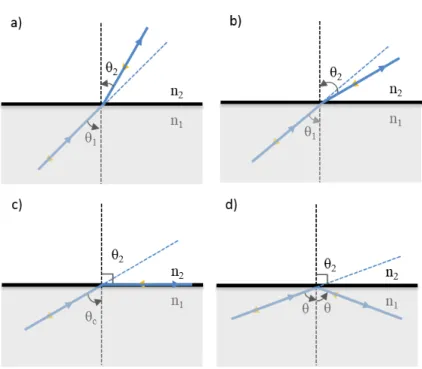
the incoming ray is partially reflected from the boundary and refracted through the next medium, as represented in figure 2.2.b. In figure 2.2.c, critical angle condition is represented when n1>n2 . Incoming ray could not pass through the
next medium when θ2 becomes π2 and θ1 becomes critical angle (θcritical) [18]. The
refractive index of the medium that ray is coming from must be greater than the refractive index of the next medium. The critical angle can be extracted from the equation 2.2 below:
Figure 2.2: Snell Law. The cases are a) n1<n2 , b)n1>n2, c) θc : critical angle
when ,n1>n2 , d) total internal reflection (TIR), n1>n2 and θ> θc .
θc = arcsin(
n2
n1
) (2.2)
For instance, the critical angle between air and glass can be found as 41.8◦ since refractive index of the air is 1 and that of the glass is 1.5 by using equation 2.2. θc= arcsin( 1 1.5) = 41.8 ◦ (2.3)
2.1.3
Total Internal Reflection
Total internal reflection is a special case when propagating ray hits to a boundary between two media having different refractive indices, and it is reflected totally from that point without any refraction since the angle between the surface and the normal is larger than the critical angle for that boundary [19]. When θ1 is
greater than the θc, all the incoming rays begin to reflect from the boundary,
none of them passes through the next medium and travel through the medium where they are coming from. This is called as total internal reflection (TIR). The total internal reflection is shown in the figure 2.2.d. This phenomenon is the fundamental case for fiber optics. Optical fibers are cylindirical wave guides that allow the light waves propagating with a low loss. The waves coupled inside an optical fiber travel by confirming the TIR. The signal loss due to reflection and refraction is minimized since the geometry of the optical fibers and refractive index distribution inside the optical fiber are set in order to confirm TIR. In figure 2.3, an optical fiber is represented. The rays are travelling inside the fiber with totally reflecting from the core and cladding boundary. The rays prefer to propagate inside the core due to refractive index distribution and coupling angle to the fiber. The coupling is another important issue for fiber optics. It will be explained in the following two subsections.
Figure 2.3: Total internal reflection (TIR) inside an optical fiber. The case for refractive index of media: ncore>nclad>n0, the case for reflection angles is θ>θc.
n0 is refractive index of air, θ0 is acceptance angle, Rcore is diameter of the core,
and Rclad is the diameter of the cladding
2.1.4
Numerical Aperture
An optical fiber can be considered as a cylindrical dielectic waveguide which is composed of two concentric glass cylinders. One of them is core having refractive index ncore, the other one is cladding having refractive index nclad. In order to
than nclad. The medium outside can be considered as air having refractive index,
n◦, smaller than both ncore and nclad. These refractive index values form the
coupling conditions for an optical fiber. Every optical fiber has a numerical aperture (NA) which is one of the feature that implies the coupling condition inside the fiber [20]. Numerical aperture depends on refractive indices mentioned above, ncore, nclad and n◦. The formula is for NA can be written as:
N A =qn2
core− n2clad (2.4)
For instance, the numerical aperture value of the fiber having ncore = 1.4501
and ncladding = 1.3923 can be calculated as using equation 2.4:
N A =√1.45012 − 1.39232 = 0.40 (2.5)
2.1.5
Acceptance Angle
The angle which is the maximum boundary for allowing TIR and providing the light coupling inside the optical fiber is called as acceptance angle. The acceptance angle is represented in figure 2.3. This angle is also refered as half-cone angle (in 3D). If the incoming ray angle with fiber end-face normal is smaller than the acceptance angle, the ray couples into the fiber and travels with TIR. These kinds of rays are called as bounded modes. If the angle between fiber end-face normal is greater than acceptance angle, the ray could not couple into the fiber and TIR cannot occur inside the fiber. Then, the ray is refracted from the cladding to air or evanesce in the cladding. These kinds of rays are called as unbounded modes. If we write the acceptance angle condition to the equation 2.1:
n◦sin θ◦ = ncoresin(90 − θcritical) (2.6)
When cos θc=sin(90 − θc), it becomes cos θc=
q
1 − sin2θcritical. Also, using
θ◦ = arcsin(
N A n◦
) (2.7)
For instance, acceptance angle of the fiber having numerical aperture 0.40 can be calaculated using equation 2.7, in the air medium which assumed to have refractive index value as 1:
θ◦ = arcsin( 0.40 1 ) = 23.57 ◦ (2.8)
2.1.6
Brewster Angle
Brewster angle is such a condition that the polarization of the light get impor-tance. At Brewster angle, the reflection coefficient becomes zero for p-polarized light when the polarization is parallel to the normal of plane. There is no such angle confirming this condition for s-polarized light [21]. Therefore, the reflected light becomes p-polarized when unpolarized light hit the boundary. The illus-tration for this condition can be considered as figure 2.2.a or b. For this case, reflection and transmission coefficients are important. Reflection and transmis-sion coefficients can be written as following and the Brewster angle is calculated among them [22]: rp−polarized = n1cos θ2− n2cos θ1 n1cos θ2+ n2cos θ1 (2.9) tp−polarized= 2n1 cos θ1 n2cos θ1+ n1cos θ2 (2.10) rs−polarized = n1cos θ1− n2cos θ2 n1cos θ1+ n2cos θ2 (2.11) ts−polarized = 2n1 cos θ1 n1cos θ1+ n2cos θ2 (2.12)
n21cos2θ2 = n22cos 2θ
1 (2.13)
Using trigonometrical formula:
n22 n2 1 cos2θ1 = 1 − n21 n2 2 sin2θ1 (2.14)
Since cos x = sec x1 , the equation becomes:
n22 n2 1 = sec2θ1− n21 n2 2 tan2θ1 = 1 + (1 − n21 n2 2 ) tan2θ1 (2.15)
And, the θ1 becomes Brewster angle, θB :
θB = arctan
n2
n1
(2.16)
The Brewster angle between air (n◦ = 1) and glass (nglass = 1.45) can be
calculated as: θB = arctan 1 1.45 = 34.59 ◦ (2.17)
2.1.7
Multi Mode and Single Mode Fibers
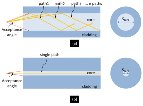
The rays enter the fiber if it is in the limit of acceptance angle and then, they travel inside the optical fiber. They follow a path inside the fiber core where the rays are travelling. These paths are called as modes inside an optical fiber. If the core of the fiber is large enough, rays have many paths to travel, and the fiber is called as a multimode fiber. If the core of the fiber allows only one path to travel, then fiber is called as single mode. The illustration is represented in figure 2.4:
Figure 2.4: Illustration of (a) multimode and (b) single mode fibers The radii of the core and the cladding give an idea about the mode-distribution inside the fiber. For multimode fibers, the Rcore is approximately 50µm or larger.
For single mode fibers, Rcore has a value between 2 − 10µm [23].
2.2
Electromagnetic Theory for Optical
Radia-tion
The light is an electromagnetic wave. In order to explain light travelling inside an optical fiber, electromagnetic theory is used. Maxwell equations explain the mathematics of the wave-like behaviour of the light [24]. The electromagnetic waves are investigated to understand wave-like nature of the light inside a cylin-drical dielectic medium, which is optical fiber.
2.2.1
Electromagnetical Waves
Maxwell equations are written as below equations 2.18 to 2.21 [25]. ~E is electric field, ~H is magnetic field, ~D is electric flux density, and ~B is magnetic flux density and ρV is electric volume charge density. In equation 2.18 [25],
∇ × ~E = −∂ ~B ∂t (2.18) ∇ × ~H = −∂ ~D ∂t (2.19) ∇· ~D = ρv (2.20) ∇· ~B = 0 (2.21) when, ~ D = ε ~E, and ~B = µ ~H (2.22)
Taking curl of ∇ × ~E and ∇ × ~H, we get: ∇ × (∇ × ~E) = −µε∂ 2E~ ∂2t (2.23) ∇ × (∇ × ~H) = −µε∂ 2H~ ∂2t (2.24)
Using the identity ∇ × (∇ × ~A) = ∇(∇· ~A) - ∇2A :~
∇2E = µε~ ∂ 2E~
∇2H = µε~ ∂ 2H~
∂t2 (2.26)
Scalar wave equation which is also known as Helmholtz equation:
∇2Ψ = 1
υ2 p
∂2Ψ
∂t2 (2.27)
From below equation, we obtain velocity of light in that medium: υp = 1 √ µε = 1 √ µrµ0εrεr (2.28)
Ψ could be either ~E or ~H. υp is the velocity of the light in that medium. Thus,
it becomes the speed of light in vacuum.
c = √1 µ0ε0
= 3 × 10⁸m
s (2.29)
For the cartesian coordinates left hand side of the equation 2.27 becomes:
∇2Ψ = ∂2Ψ ∂x2 + ∂2Ψ ∂y2 + ∂2Ψ ∂z2 (2.30)
Cylindrical coordinates for Helmholtz equation 2.27 becomes:
∇2Ψ = ∂ 2Ψ ∂r2 + 1 r ∂2Ψ ∂r2 + 1 r2 ∂2Ψ ∂φ2 + ∂2Ψ ∂z2 + n 2 k20Ψ (2.31)
The solution of the wave-equation is given as:
Ψ = Ψ0expi(ωt − ~k· ~r) (2.32)
Ψ = Ψ0expi(ωt − kxt − kyt − kzt) (2.33)
Where ω is angular frequency, t is time, ~r is the coordinate for measurement point and ~k is the propagation vector. ~k can be explained as below formula:
k = |~k| = 2π
λ (2.34)
where λ stands for wavelength of the light (wave).
2.2.2
Modes in Planar Waves
In order to ensure that light traveling inside core - cladding boundary with same phase after a few reflections, there are essential conditions. There are specific angles and bounded modes that allow the light propagation. These angles and modes can be specified with propagation constant, written in equation 2.35. [26]:
βz = ncorek0sin θ =
2π
λ (2.35)
There are mainly three cases for β values, and they are explained as in the following:
case 1: 2πλ ncladding < β < 2πλ ncore ; The light travels inside the core obeying
the TIR.
case 2: 2πλncoating < β < 2πλ ncladding ; The light travels inside cladding, totally
reflected from cladding - coating boundary.
case 3: β < 2πλ ncoating ; The light can not travel inside the fiber, it couples
2.2.3
Spatial Distribution of Modes in Cylindrical
Waveg-uide
Helmholtz equation 2.27 is solved in order to indicate spatial distribution of the modes in a cylindrical waveguide (optical fiber). Using ω = 2πf , Helmholtz equation (eqn. 2.27) can be written as following:
∇2Ψ = n2(k
0)2Ψ (2.36)
The modes in propagating waves are in the direction of fiber, z-direction. Ψ is a periodic function since it represents a wave. Thus, Ψ can be written as periodic function with harmonic terms as e−idϕ, and the solution becomes:
Ψ(r, ϕ, z) = Υ(ψ(r)e−idϕe−iβz) (2.37)
In order to simplify these equations and eliminate the complex part, we can write equation 2.37 into equation 2.31, and we get differential equation for Bessel functions: ∂2ψ ∂r2 + 1 r ∂ψ ∂r + (n 2k2 0− β 2− d2 r2)ψ = 0 (2.38)
Modes that are coupled into the core should satisfy ncladdingk0 < β < ncorek0,
kT2 = n2corek20− β2 (2.39) and ρ2 = β2− n2 claddingk 2 0 (2.40)
From equation 2.38. : ∂2ψ ∂r2 + 1 r ∂ψ ∂r + (k 2 T − d2 r2)ψ = 0 (2.41) ∂2ψ ∂r2 + 1 r ∂ψ ∂r − (ρ 2 +d 2 r2)ψ = 0 (2.42)
Equation 2.38 becomes equation 2.41 for core and equation 2.42 for cladding. These equations can be solved by Bessel functions when approaching infinity at r −→ 0 in the core and r −→ ∞ [27] .
2.3
Types of Fibers
Basic characteristics of the optical fibers are investigated in the previous sections. In this section, basic refractive index distributions of the optical fibers are studied. This distribution is an important characteristic for fibers [28]. Refractive index distribution affects the TIR and guiding inside the fiber. There are fibers having different refractive index distributions such as step-index, graded-index, panda mode, photonic crystal and so on [29]. In this section step-index and graded-index fibers are covered.
2.3.1
Step Index Fiber
In figure 2.5.a, a step-index fiber is illustrated. The refractive index distribution has a rectangular shape. Core and cladding boundary has a sharp difference in refractive index values. Rays are totally reflected from that boundary.
Figure 2.5: a)Step-index and b) graded-index fiber.
2.3.2
Graded Index Fiber
In figure 2.5.b, a graded index fiber is represented. The refractive index dis-tirbution has semi-circle shape. There is no sharp boundary between core and cladding, therefore, the refractive index changes gradually from core to cladding. The rays are refracted gradually, they follow a bended-path and at some point between core and cladding, they are totally reflected. The graded-index fibers represent less mode-dispersion comparing to step-index fibers.
2.4
Losses in Optical Fibers
In the earlier developments, low-loss optical transmission was achieved with ∼ 0.2dB/km loss as mentioned in Chapter 2. There are three basic loss mechanisms in optical transmission in fibers namely scattering, absorption and bending loss. In figure 2.6, the loss mechanisms are represented. In the scattering case, a photon hits a boundary and changes its direction and photon may exit the fiber medium. The scattered photon continues to propagate outside the fiber. In the case of absorption, a photon propagating inside the fiber is absorbed by impurities or dopants, converted to energy and causes heat. The absorbed photon disappears
inside the fiber. In the case of bending, the loss is independent from composition of the fiber (dopant, impurities), rather it occurs due to shape of the fiber. If the fiber is bended, the TIR could be violated, thus, the rays could not be reflected totally from the bended point, and they are partially reflected inside the fiber and refracted through the outside of the fiber [30].
Figure 2.6: Three cases for power loss mechanism of optical fiber. (adapted from [30])
Chapter 3
Fiber Optic Probes
Fiber optic probes are quite useful tools for medical applications for treatment of diseased hollow organs [31]. They have a potential to improve clinical prac-tice since the integration of fiber optic probes to medical lasers are used in the treatment of several diseases such as venous relux [32], breast [33] and prostate tumors [34]. Fiber optic cables are extensively prefered in the clinical environ-ment due to their various advantages [35]. One of the advantage is that they could allow the laser beam to be transmitted non-linearly. Another advantage of fiber optic probe can be considered as the fiber optical connector which is the connection piece of the fiber with the laser device providing the fiber probes plug in and out without optical alignment [36]. Also, fibers can have various diameter values, ranging hundreds of microns to milimeters. Hence, it is easy to insert fibers into the diseased body parts due to their small diameters and they are used in minimally invasive laser theraphy. Minimally invasive applications pro-vide a comfortable treatment period for patients [37]. It is safe to use, effective operational result and flexible structure. Fiber optical cables both transmit the laser energy to the targetted tissue and they deflect the laser energy with different emission shapes by manipulating their tip geometry [38]. It is possible to deflect the laser beam not only the same direction with the fiber but also side direction or radially. These fiber tip geometries are used for a specific medical application.
For example, flat-ended and radial fibers are used in Endovenous Laser Abla-tion (EVLA), side-firing probes are used in tumor ablaAbla-tion, diffusing probes are used in photodynamic theraphy [39]. In this chapter, development procedure of flat-ended, side-firing, radial emitting and diffusing fiber optical probes are dis-cussed in terms of ray tracing analysis, modelling, fabrication and light deflection measurements. Their medical application fields are also mentioned. In the ray tracing analysis part, the rays were examined for flat, side-firing and radial tip geometries and the theories were used such as total internal reflection, Snells Law. After theoretical analysis, the ray tracing and light deflection were investigated by Zemax modelling. The fiber tip geometries were studied, and the fiber tip angles were determined, then the fiber optical probes were fabricated.
3.1
Designing a Fiber Optical System at Zemax
Zemax (Zemax,LLC, Germany) has been serving as an optical design software for 25 years and it has been used for developing, analyzing and improving optical systems such as imaging and illumination optics, lenses, mirrors and fibers [40]. The program models optical systems by using ray tracing. Rays come through the optical system and the program compiles the rays according to wavelength of the incoming rays, refractive index of the piece of the optical system, distance between optical parts of the system. Glass type is assigned by choosing the glass type from the library available in the software. The commercial lenses are also available in the library. There are three options to design an optical system: sequential, non-sequential and combination of sequential/non-sequential. In the sequential option, optical elements are analyzed by creating the optical system surface boundary by surface boundary. The rays are traced through the image plane and the features such as spot diagram, ray-fan plots can be analyzed. It is possible to give tolerance to the lenses due to manufacturing issues and optimize the lenses, and also fixing the aberations. In the non-sequential option, stray light and physical beam propagation can be analyzed. The geometry of the optical system can easily be created in the program by using non-sequential mode. There is another option, which is composed of both sequential and non-sequential.
This option combines the features of both. In our study, ray propagation inside the optical fiber and the fiber tip geometries were modelled. The best option is the non-sequential mode which is widely used for designing the optical fibers [41, 42]. Optical fiber propagation and the tip geometries were modelled in the non-sequential option and the deflection characteristics were analyzed.
3.2
Fabrication Procedure of Fiber Optic Probes
The first and crucial step for using fiber optic probes in medical applications is preparing the end-face of fiber optic precisely. The end-face of the optical fiber should be smooth in order to reduce the optical loss due to light scattering [43]. There are several optical fiber fining techniques such as hand polishing, mechan-ical polishing, acid etching and recently studied laser polishing procedures [44]. Fiber optical polishing is mainly starts with rough polishing to form the shape of the fiber tip. After the tip geometry is formed as flat, side-firing or conical, fine polishing is applied to complete the polishing procedure. Fine polishing is the crucial part since it is hard to polish the tip without deforming its shape. In this chapter, mechanical and laser polishing procedures are studied. Mechanical polishing is more widely used, however, it has some disadvantages such that it depends on the laborer, the time spent on polishing films is long. Laser polishing can be considered as a potential solution to disadvantages of mechanical polish-ing. However, the tip geometries cannot be formed by using only laser polishing, as will be explained in section 3.2.2. Therefore, the fiber tip geometries can be formed by rough mechanical polishing and fine polishing is applied by the laser radiation. Thus, process would be independent from laborer and takes less time [45].
3.2.1
Mechanical Fabrication Procedure
In order to form and fine the end-face of the fiber optic probe, mechanical polish-ing is widely used [46]. The process is basically rubbpolish-ing the fiber end-face on the
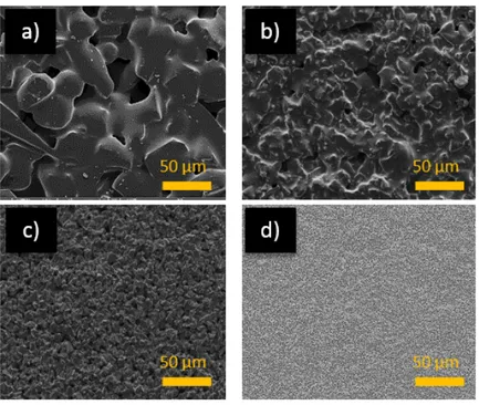
polishing films. The fiber is inserted inside the jig and the end-face of the fiber is pressed onto the films sticked on the disk. The films are changed according to their roughness, starting from rough to finer ones. Thus, the roughness of fiber end-face is also changed implicitly. There are commercially available polishing films: KrellTech (USA) and ThorLabs (USA). In our study, we used KrellTech polishing films and the roughness follows the order as 30µm, 9µm, 3µm, 0.3µm. In figure 3.1, KrellTech polishing films are shown. Flat-ended, side-firing, ra-dial, double-ring radial and even diffuser fiber optical probes can be fabricated by using these films. Furthermore, the SEM images of KrellTech polishing films
Figure 3.1: Polishing films having roughness a) 30 µm ,b) 9 µm ,c) 3 µm and d) 0.3 µm .
are shown in figure 3.2, and it is clearly seen that there are sharper and larger aluminum oxide particles in the rougher films. The particle sharpness and size are reduced which also allows decreasing the surface roughness of the film. These films are composed of alumina particles which are stronger materials than glass. Therefore, alumina particles located in the films can create abrasion on glass.
Figure 3.2: SEM images of polishing films having roughness a) 30 µm ,b) 9 µm ,c) 3 µm and d) 0.3 µm
as 400/425/730 micrometer. The core/clad/coating is composed of Silica/TECS (Hard Polymer Coating)/Tefzel buffers, respectively. The fiber’s NA is 0.39 and it operates at 200-2200 nm low-OH fiber [ThorLabs, USA]. The fiber polisher is KrellTech-Trig Lite Fiber Polisher [USA]. In order to obtain flat-ended fiber tip, the fiber was positioned vertically (90◦) to the polishing film.
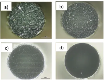
Figure 3.3: Optical microscope images of polished fiber end-faces having rough-ness a) 30 µm, b) 9 µm, c) 3 µm and d) 0.3 µm
In figure 3.3, polished fiber end-faces with different roughness are shown. Op-tical microscope images were taken in the dark field mode. The scratches, cracks and hitches can be seen clearly in the fiber end-face polished with 30µm polishing film in figure 3.3.a. In figure 3.3.b and c, the roughness slightly disapears and a smooth fiber end-face was achieved by using 0.3µm polishing film, and scattering losses became negligible shown in 3.3.d.
Figure 3.4: Polishing procedure for a) Flat-ended, b) side-firing, and d) radial fiber optical probe
As mentioned previously in this chapter, in order to use the fiber optical probes for medical applications, these polishing procedures should be applied first to flat-ended, side-firing and radial tip fibers. Side-firing and radial fiber probes are required to be positioned with an angle into the polishing machine as shown in the figure 3.4.b,c. Besides, in order to form conical shape, fiber rotates around its axis its center while polishing as represented in figure 3.4.c.
3.2.2
Laser Polishing Procedure
Laser polishing can be applied to the materials absorbing the radiation when 10.6µm CO2 laser is exposed. The main principle of laser polishing is that thin
layer of a material melts for a while and cools down after radiation [47]. The surface absorbing the radiation becomes smooth due to surface tension. In the silica-glass laser polishing process, low photon energy of the CO2 laser (0.2eV ) is
not enough to brake Si-O bonds [48]. The laser radiation is absorbed by surface and this energy is converted to thermal energy. For silica-glass material, the absorption is very high in that regime, in the order of 103cm−1 [49]. The laser
radiation is absorbed by a thin layer with a very small penetration depth inside the material. The temperature of the silica does not reach the glass transition temperature when exposed to CO2 laser since the energy is low [48]. Therefore,
glass is not transferred to the liquid state, it stays at viscoelastic region. Using this effect as an advantage, the glass surface could be fined by 10.6µm CO2 laser
radiation [50]. The scattering and back reflection losses are minimized due to elimination of the imperfections existed after mechanical polishing. The laser
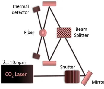
Figure 3.5: CO2 laser polishing setup.
polishing setup used throughout the experiments of this study is shown in figure 3.5. The laser beam splits into two beams by beam splitter and is combined onto the fiber surface by mirrors. Thus, the fiber is exposed to the laser energy
from both sides homogeneously. The shutter can be used as a chopper and it can transform continuous wave (cw) to pulsed wave (ps). The power of the CO2 laser is measured by thermal detector. This scheme belongs to the
LZM-100 LAZERMaster Laser Splicing System (AFL, USA). This device is usually used for tapering and splicing optical fibers using 10.6µm CO2 laser radiation.
Taking the advantage of writing special function which contains modulated laser energy (pulsed, chirped or continuous wave) into the device, the fiber end-face can be polished. The optical microscope images of laser-polished flat-ended fibers
Figure 3.6: Optical microscope images of the same fiber end-face (a) fine mechan-ical and (b) after laser processed.
are shown in figure 3.6, the demonstration of laser polishing of flat-ended fiber is shown. The function written into the device is composed of 8 pulses of laser energy with 1s duration and 1s interval. Laser power density is 9.15x10³ W
cm2. Figure 3.6.a
belongs to fine-mechanically polished fiber end-face and figure 3.6.b belongs to the same fiber after laser radiation was applied. The images were taken in the differential interference contrast (DIC ) mode. The cracks and scratches cause light scattering from the tip, and thanks to the laser polishing, all cracks were eliminated and the scattering disapeared due to laser polished smooth surface.
3.3
Radial Fiber Optical Probe
The direction of the laser beam can be controlled by forming the fiber tip with appropriate geometry. Conical tip fiber emits the light radially. The deflection of laser beam is 360◦ with homogeneous ring shape around the fiber tip. Radial (360◦) emission is useful for many minimal invasive medical operations inside the tubular organs. The shape of output beam strongly depends on the tip angle. Cone tip angle should be determined according to the characteristics of both the fiber and the laser. The cone tip angle must provide that the laser power coupled into the fiber exits with minimum loss and that all the power should be localized into the ring shape emission, not the same direction along the fiber. The homogeneous ring shape laser emission provides homogeneous photothermal destruction inside the tubular organs, therefore, only the desired tissues are eliminated by laser ablation [51].
Cone tip fiber is encapsulated in a glass capillary to avoid tissue pieces and other materials from damaging the tip shape which causes a change in laser de-flection. It is also important to protect the body from any damage which can originate from any possible fiber tip breaks [52]. In this section, the aim is to examine the cone shape optical fiber tip in terms of ray tracing and modelling in order to decide the appropriate cone angle for fibers having core/cladding/coating diameter 600/630/1040 µm fibers [53]. The ray tracing theory is combined with experimental results to fabricate the perfect radial fiber. It is also an impor-tant challenge to fabricate radial fibers with a fine end-face surface. The surface roughness for each lapping film are represented and the light deflection calcula-tions and measurements are explained. Mechanical polishing is a common fab-rication procedure. However, as mentioned before, it is a time consuming and laborer dependent process. Although smooth surface roughness can be achieved by mechanical polishing technique, there is another way to polish cone tip, CO2
laser polishing. Laser polishing process takes less time and it is completely in-dependent from laborer. However, the tip shape cannot be completely formed by continuouswave(cw) − CO2 laser. The solution is to combine these two
laborer dependence. The shape of the cone tip was formed first by mechanical rough-polishing and the laser radiation was, then, exposed to the tip to make it smoother. Light deflection measurements, SEM and AFM analysis were per-formed to show the changes in the radial tip fiber before and after the laser irradiation.
In this study, the main application of the modelled, fabricated and tested cone-shaped fiber optical probes is the treatment of venous reflux, which is a very common disease. Approximately 55% of women and 45% of men suffer from symptoms such as fatigue, pain and swelling of lower limbs [51]. Hormonal changes, standing or sitting for a long time might lead to this disease. The venous reflux is completely treated by laser ablation method using radial fiber probes. Laser system for this application was built by our research group and E-A Teknoloji Biyomedikal Cihazlar Dijital ve Optik Sistemler Nanoteknoloji Ar-Ge ˙Ith. ˙Ihr. Taah. San. ve Tic. Ltd. S¸ti. and the tests of the laser device is represented in Chapter − 4.
3.3.1
Ray Tracing
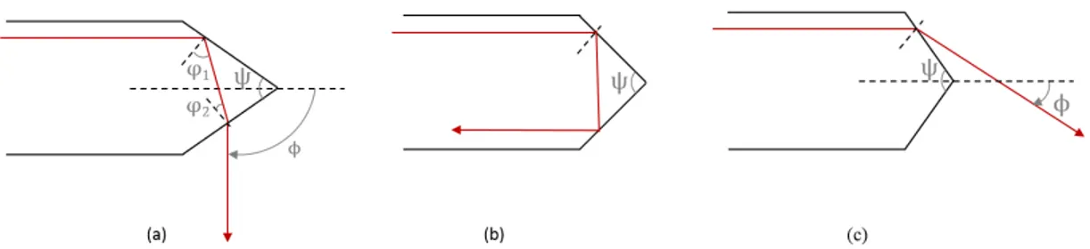
Ray tracing can be divided into 3 possible geometries. These geometries were explained by using total internal reflection, partial reflection and refraction and the ray deflection from conical tip was formulized [54]. In order to simplify the ray tracing system, rays are traced parallel to the tip. The side-firing deflection is represented in figure 3.7.a. Incoming ray is reflected (according to TIR) from first side of the fiber tip, and refracted from second side of the tip. In figure 3.7.b, incoming ray is reflected from both sides of the fiber tip and totally back reflected. In this case, ray cannot be deflected from fiber tip. In figure 3.7.c, ray refracted from first side of fiber tip without reflecting.
Relation for these cases can be written as equations below: Relation for 3.7.a:
Figure 3.7: Ray tracing analysis for conical tip fiber. Relation for 3.7.b: π − 2θcritical > ψ > π + θcritical 3 (3.2) Relation for 3.7.c: ψ > π − 2θcritical (3.3)
θcritical for ncore− nair boundary can be calculated as 43.6◦ by using equation
2.2. Deflection angle versus tip angle relation for case (a) can be calculated as:
φ = π − ψ
2 + arcsin( ncore
nair
sin ϕ2) (3.4)
Deflection angle versus tip angle relation for case (c) can be calculated as:
φ = arcsin(ncore nair
sin ϕ1) − ϕ1 (3.5)
Deflection angle versus tip angle relation cannot be calculated since arcsin does not have values for case (b).
3.3.2
Zemax Modelling
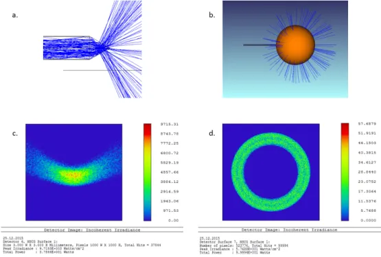
Ray tracing analysis was studied by Zemax in non-sequential mode for radial fiber. Fiber geometry was constructed so that the core/cladding diameter of the
fiber was 600/300 micrometer, the NA of the fiber was 0.39, the NA of the light source was 0.22 and the wavelength of incoming rays was 635 nm. 100000 rays were analyzed and 100 rays are shown in figure 3.8.a and in figure 3.8b., radial diffusion is shown when hemi-spherical dedector is put inside the fiber tip. The tip angle was formed at 60◦ to observe the light deflection from the tip.
Figure 3.8: Zemax ray tracing simulation for radial fiber.
In figure 3.8.c, rectangular dedector image, which shows the spatial beam profile of the radial fiber tip, is represented. In figure 3.8.d, the ring-shaped beam profile is shown in hemi-spherical detector surface and the perfect ring shape can be obtained when the tip angle is chosen as 60◦.
3.3.3
Fabrication and Light Deflection Measurements
In order to obtain circular beam, the fiber tip was formed with cone-shaped geometry. Cone-shaped fiber tips were fabricated by polishing on aluminum oxide particle coated lapping films. Mechanical and CO2 laser polishing were both
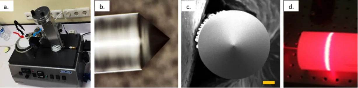
Figure 3.9: Fabrication procedure of the side-firing fiber probe. (a) Polishing procedure, (b) optical microscope image, (c) SEM image (scale bar: 100µm), (d) spatial distribution of radial probe.
The polishing machine (Ultrapol, USA) represented in 3.9.a was used for me-chanical polishing process. The red arrow indicates the turning table which has a lapping film on the top side and the blue arrow indicates the fiber holder. The tip angle can vary by changing the slope of the fiber holder and the detector displays the exact angle. Side-firing and radial fiber probe tips can be fabricated by this polishing machine since both the lapping film and the fiber holder are allowed to rotate. Also, the rotation speed can be altered. Optical microscope image and SEM image of the radial fiber tip are represented in figure 3.9.b and 3.9.c, respectively. In figure 3.9.d, circular beam distribution of radial fiber tip is demonstrated. The fabrication process will be explained in the next section in detail.
3.3.3.1 Mechanical Polishing
Fibers used in this process had 600/630/1040µm core/cladding/coating diameter. The cleaved, flat-ended fiber was inserted inside the fiber holder as shown in figure 3.9.a and the angle was set to 60◦. Rough-lapping film (30µm) was sticked on the turning table, and started to rotate around its axis. The fiber tip approached to the rotating lapping film gently. The lapping film cause an abrasion on the end-face of the fiber tip, then the forming of the tip shape began. After the tip is formed by the rough film, the fine polishing step is started with the lapping films having lower surface roughness with 9µm, 3µm and 0.3µm. SEM images of fibers polished with films having roughness (a) 30µm, (b) 9µm, (c) 3µm and (d)
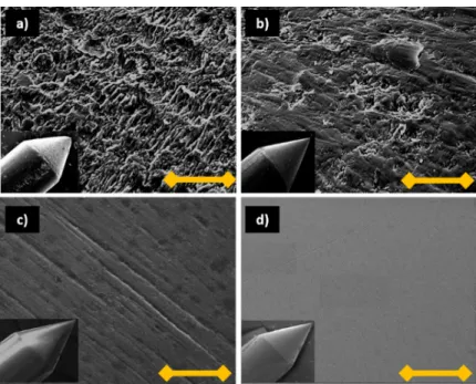
0.3µm in figure 3.10 respectively.
Figure 3.10: SEM images of optical fiber surfaces after polished at (a) 30µm, (b) 9µm, (c) 3µm, (d) 0.3µm films. (Scale bar: 5µm)
Rough lapping film (30µm) provides forming the fiber tip shape. However, its surface was not enough to be used in an operation (EVLA) and it was aimed to make it smoother in the subsequent steps. As shown in the figures 3.10, the surface roughness was gradually reduced with the applied lapping film roughness and, finally, smooth surface was achieved.
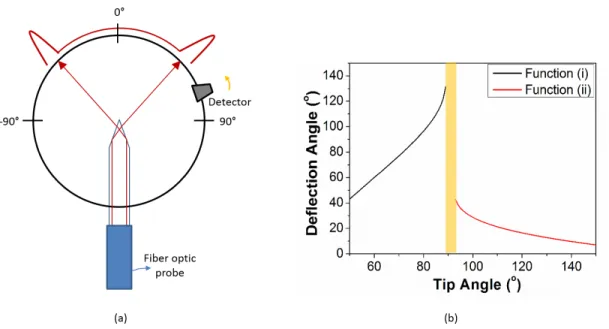
In order to emphasize the effect of the fiber tip surface roughness on the light deflection, an in-house built set up was used to measure the light deflection. In figure 3.11.a, the schematic representation of the setup is shown. The fiber tip is positioned in the center of the detector’s circular path. The detector was allowed to rotate in the range between −90◦ and + 90◦. The detector rotates around the fiber tip while recording the power value. The resolution was 1◦ meaning that the power value was recorded at each degree. In figure 3.11.b, the deflection angle versus tip angle graph is shown. In the ray tracing part, the deflection from the tip characteristics due to tip angle was examined and the deflection angle was determined for each possibilities. The relation between the tip angle and the light deflection angle is indicated in this figure. There were three functions to
Figure 3.11: (a) Scheme of light deflection measurement setup for conical fiber. (b) Graph of deflection angle versus tip angle.
explain the light behavior: function (i) refers to equation 3.4, the function (ii) refers to 3.5 and the yellow discontinuity region refers to relation 3.2 . This graph was plotted according to these equations while ncore was 1.4501 and ncladding was
1.3923.
The light deflection differs due to roughness of the fiber surface. The rougher the fiber surface, the more the light diffuses. The cone-tips having smooth surface roughness are inserted into a glass capillary by fusing with gas-oxygen torch as shown in figure 3.12.a. The beam profiler image is shown in figure 3.12.b. In figure 3.12.c, the graphs are plotted for fiber tips polished at (i) 30µm, (ii) 9µm, (iii) 3µm and (iv) 0.3µm lapping films. The tip angle of the fabricated fiber was 60◦ and its deflection should be at 60◦. The peak power increases due to reduced surface of fiber tip. The the smaller beam width obtained when the roughness was diseapeared due to fine polishing. Also, deflected laser beam was located at 60◦ as calculated when ncore = 1.45, ncore = 1 and tip angle ψ = 60◦ using equation
3.4. The final product of radial fiber probes were developed by our group and company. This product is succesfully applied in an EVLA operation and now commercially available.
Figure 3.12: (a) The final form of the tip of the radial fiber probe, (b) beam profile of radial optical probe. SEM images of optical fiber surfaces after polished at (i) 30µm, (ii) 9µm, (iii) 3µm, (iv) 0.3µm films.
3.3.3.2 Laser Polishing
The conical fiber tips were exposed to CO2 laser radiation after the tip shapes
were formed by mechanical polishing. The LZM100(AFL) was used as mentioned before. The laser power was modulated by using shutter (shown in figure 3.5) as a chopper. The function which modulated the laser beam was written into the device. It was composed of 8 pulses of laser energy with 1s duration and 1s inter-val. Laser power density was 9.15x10³ Wcm2. These parameters were optimized due
to laser polishing of the flat-ended fiber tip. The SEM images of laser polishing of radial fibers polished at 30µm and 9µm films and then processed with CO2
(a) and (b) are shown in the figure 3.13. In figure 3.14, surface roughness images taken by AFM are represented. In figure 3.14, (a) fine mechanical polished fiber surface is shown with 1.17nm, CO2 treated fiber tips after polished with (b) 9µm
film with 3.38nm, (c) 30µm film with 7.87nm average roughness. In the liter-ature, Udrea et al. obtained 100nm average surface roughness of fiber end-face surface after polishing with cw-CO2 [48].
Figure 3.13: SEM images of CO2 laser treated fiber tips after polished at: (a)
30µm , (b) 9µm films. (a) 30µm , (b) 9µm films. (Scale bar: 5µm)
Also, in order to clarify the effect of the roughness to the intensity, the mea-surements were performed for both steps. Light deflection graphs for the fiber tips, which were laser processed after polishing on 30µm and 9µm films, are shown in figures 3.15.a and 3.15.b, respectively. The light deflection measurements for each case have less power intensity after mechanical polishing was applied. For
Figure 3.14: AFM images of (a) fine mechanical polished, CO2 laser treated fiber
tips after polished at: (b) 9µm , (c) 30µm films.
each case, the power increases after laser polishing was applied. Thus, the la-borer dependent and time-consuming steps were skipped thanks to the CO2 laser
polishing.
Figure 3.15: Deflection measurements CO2 laser treated fiber tips after polished
at: (a) 30µm , (b) 9µm films.
3.4
Double-Ring Radial Fiber Optical Probe
Double ring fiber optic probe has a modified cone-shaped tip geometry. It splits the laser power into two rings. Double ring light deflection is very effective for
endovenous laser ablation (EVLA) operation. The burning effect is reduced due to less energy density of each ring. Also, the first ring playing as a pre-heater role which allows to pre-shrink the vein and ablation process becomes more effective. A patented commercial product is available in the Biolitec (Germany). The geometry of the tip is composed of two cones with different cone angles. First cone is polished from the tip through the middle of the cone and its shape becomes flat-ended equilateral parallelogram. The second tip is spliced to flat side of the end of the first tip [55]. The process includes polishing, splicing, and cleaving which are not easy steps. In our group, we produced, modelled, and measured home-made double ring fiber probe which was fabricated by another technique. It is an ongoing project to commercialize this product by getting its patent. Therefore, we are not able to show the tip geometry, but the Zemax modelling and light deflection measurements are represented in this study.
3.4.1
Zemax Modelling
Ray tracing analysis is studied by Zemax in non-sequential form for double-ring radial fiber. Fiber geometry was constructed so that the core/cladding diameter of the fiber was 600/630, the NA of the fiber was 0.39, NA of the light source was 0.22 and the wavelength of the incoming rays was 635nm. 100000 rays were analyzed, 100 rays are shown in figure 3.16.a and in figure 3.16.b, double-radial emitting tip is shown when hemi-spherical dedector is put outside of the fiber tip.
3.4.2
Light Deflection Measurements
Double-ring emitting fiber tip is formed by mechanical polishing. Light deflec-tion measurements were taken in the setup shown in figure 3.11.a. The laser beam coming inside the optical fiber, splits into two beams when exits from the modified fiber tip. In figure 3.17.a, demonstration of double ring emitting fiber is represented. Two beams can easily be seen image taken by beam profiler in 3.17.b. In graph 3.17.c, double-ring pattern is shown. We also proposed that the power distribution can be altered due to geometry of the fiber tip.
Figure 3.17: Light deflection measurements. (a) Spatial distribution, (b) beam profiler, (c) light deflection measurements of double ring radial fiber-optic prob.
3.5
Side-Firing Fiber Optic Probe
Side-firing fiber optical probes are important tools in laser medicine. In the case of flat-ended fiber probes, light is transmitted as coupled out in the direction of the fiber. The deflected light direction can be controlled by changing the fiber end-surface shape. Laser beam can be emitted almost perpendicular to the fiber axis thanks to the side-firing fiber probes. The main idea is that the laser beam can be localized onto the area that is desired to be ablated. It is very important to transmit almost full power of the laser perpendically, however, the light is coupled out from the fiber tip in three ways: leakage, deflection with leakage and perpendicularly deflection from the fiber tip [56]. In order to reduce the leakage from the tip, the tip angle should be chosen specifically (this concept is explained in the ray tracing part). It is desirable to fabricate a side-firing probe without any leakage. This is important for the medical applications since the laser beam leakage could damage healthy part of the tissue. The side-firing probes are used in the medical applications. They are suitable for the removal of tissue in hollow organs. These probes are desired for urology applications. Prostate tumors can be ablated thanks to side-firing probes [34]. There are studies suggesting that small breast cancer tumors can also be eliminated using these probes [33].
3.5.1
Ray Tracing
A slanted end-face geometry of fiber provides a light beam which is directed through side of fiber tip. The tip angle is crucial to deflect maximum power without loss. Thus, Brewster angle at the air-fiber boundary should be calculated as shown in equation 3.6, when n2 stands for air and n1 is considered as refractive
index value of the fiber core: arctann2 n1 = arctan 1 1.45 = 34.21 ◦ (3.6)
The Brewster angle results in a total reflection from air-fiber boundary. Thus, the tip angle should be 34.21◦ to obtain total internal reflection without any loss
and all the laser beam is emitted through the side of the fiber theoretically. In a study conducted by Falk and Pashaie (2013), the tip angle for side-firing probe was calculated that the angle should be smaller than 38◦ for fiber having NA 0.22 using these calculations.
Figure 3.18: Ray tracing analysis for side-firing fiber tip.
In figure 3.18, ray tracing analysis is illustrated. The deflection angle depends on tip angle of the fiber [56]. Deflection angle and tip angle relation can be extracted by ray tracing analysis and from fiber tip geometrical relations. For marginal ray - I, θmax can be calculated by using equation 2.1 and 2.2:
ψ = ω − b (3.7)
θmax = 2ψ + (90 − ω
0
critical) (3.9)
The marginal ray - II can also be calculated as:
ψ = 180 − (ω + b) (3.10)
θ = 2ψ − (90 − ω) (3.11)
θmin = 2ψ − (90 − ω
0
critical) (3.12)
The angle between ncore and ncladding, ω should be larger than critical angle
which is calculated by the equation 3.14, and ω should satisfy ωcritical0 < ω < 90◦. From the tip angle calculation, we found that tip angle should be ∼ 34◦ in equation 3.6. The divergence lobe (4θ) can be found as:
4θ = θmax− θmin = 180 − ω
0
critical (3.13)
3.5.2
Zemax Modelling
Ray tracing analysis was carried out by Zemax in non-sequential form for side-firing fiber. Fiber geometry was constructed so that the core/cladding diameter of the fiber was 600/630 micrometer, the NA of the fiber was 0.39, the NA of the light source was 0.22 and the wavelength of incoming rays was 635nm. 100000 rays were analyzed and 100 rays are shown in figures 3.19.a and b. The tip angle was set at ∼ 34◦ to observe the light deflection from the calculated fiber tip.
In figure 3.19.c, rectangular dedector image, which shows the spatial beam profile of the side-firing fiber tip, is represented. 80% of the incoming rays are
Figure 3.19: Zemax ray tracing simulation for side-firing fiber.
deflected and located onto the an area. 80% can be achieved but 100% cannot be possible since we have a multi-mode fiber. In figure 3.19.d, the localized beam profile is shown in hemi-spherical detector surface.
3.5.3
Fabrication
KrellTech polishing machine was used for this process. The procedure was almost the same as the one applied to the radial fiber tips in the section 3.3.3.1. The only difference was that the fiber did not rotate around its center in order to form side-firing probe shape. The optical fiber (diameter of core/clad is 600/630 µm) was inserted inside KrellTech fiber holder. In figure 3.20.a, KrellTech polishing machine and the fabrication procedure is shown. The blue arrow indicates the rotational stage, the angle of which can be set by turning it, and it is fixed to 56◦ to form a side-firing probe having tip angle 34◦. The red arrow shows the fiber holder. The rotational speed was also adjustable for this polishing machine. In figure 3.20.b, the camera display is shown for the positioned fiber tip before the polishing. The polished side-firing tip is represented in figure 3.20.c. The light
deflection measurement is demonstrated in the figure 3.20.d.
Figure 3.20: Fabrication procedure of the side-firing fiber prob. (a) Polishing procedure, (b) before polishing, (c) after polishing, (d) spatial distribution of side-firing probe.
3.5.4
Light Deflection Measurements
The light deflection measurement setup is represented in figure 3.21.a. The data recording process was almost same as the process of radial fiber light deflection. Only difference was that the light deflection of the side-firing fiber was located onto one spot. In figure 3.21.b, the relation between deflection angle versus tip angle is plotted by using the ray tracing calculations and equation 3.13.
In figure 3.22.a, beam profiler image of laser beam is represented. Light de-flection measurements were taken in the setup shown in figure 3.21.a. In figure 3.22.b, the light deflection of the side-firing fiber was plotted when tip angle is 34◦. As seen from the figure 3.22.b, the spatial distribution of laser deflected from the fiber is located approximately at 55◦. The graph in figure 3.21.b confirms the light deflection angle due to tip angle with a few degrees error.
Figure 3.21: (a) Scheme of light deflection measurement setup for side-firing fiber. (b) Graph of deflection angle versus tip angle.
Figure 3.22: Measurements for side-firing fiber probe: (a) beam profiler image, (b) light deflection distribution of side-firing probe.