The
finite element analysis of collapse loads of single-spanned
historic masonry arch bridges (Ordu, Sarpdere Bridge)
Abdulkadir Cüneyt Aydin
a,⁎, Suat Gökhan Özkaya
baAtatürk University, Engineering Faculty, Department of Civil Engineering, 25030 Erzurum, Turkey bArdahan University, Engineering Faculty, Department of Civil Engineering, 75000 Ardahan, Turkey
A R T I C L E I N F O
Keywords:Masonry arch bridges Collapse loads Finite elements Static analysis
A B S T R A C T
The current methods used in estimating the collapse loads of masonry arch bridges have been examined, and a study has been made aiming the calculation of the behaviors of the single-spanned masonry arch bridges shows under certain loads with the method of static analysis.
The model used for the study was 3D formed with the ANSYS package program, and the results of the analysis were achieved using this program, as well. The model that was created was obtained by using the original dimensions of the historical Sarpdere Bridge located within the province of Ordu. The results obtained have shown compliance with the existing studies in the literature.
In addition, the effects of the loads on the bridge that were applied to the different places on the system were examined, and the behaviors of the single-span masonry arch bridges under the loads applied were evaluated. Thefiller and sidewalls on left and right sides of the arch bridge were differentiated the loading about 10%.
1. Introduction
Historical structures are one of the most essential parts of the cultural heritage. Historical monuments are the witnesses of our old traditions and the symbols of the cultural identity. It is not possible to understand, interpret and retrace the period of civilization, without them. They represent the details related with the technology in design, material characteristics, workmanship, architectural features and spiritual value of their periods. Actually, there exist only two basic ways to bring the past into today's world; literature and historical structures. These are remarked as the living history, on which human beings past is reflected, it will not be wrong to say that they are the proof's showing the spirit and charm of the heritage.
Conservation and restoration of historical structures require a sensitive systematic study in order to achieve proper results. In addition to a deep knowledge of the ethics of conservation, one should have good technical skills and sufficient information related to the structure and material. This means that specialized people who take the necessary education should perform the conservation of historical structures. As well, conservation requires not only a multidisciplinary work, including history, but also architecture and engineering as the basic sciences. For proper intervention, understanding of the structural behavior and good engineering judgment with sufficient experience of the old construction techniques and concepts and correct interpretation of the analysis results of comprehensive structural analyses are needed. The master historical structures was designed not only for complex load carrying system and continuous interaction of domes, vaults, arches, minarets and pillars, but also for architectural concepts and for enough light and proper acoustics.[3,9,25].
https://doi.org/10.1016/j.engfailanal.2017.11.002
Received 1 June 2017; Received in revised form 17 October 2017; Accepted 6 November 2017
⁎Corresponding author.
E-mail address:[email protected](A.C. Aydin).
Available online 07 November 2017
1350-6307/ © 2017 Elsevier Ltd. All rights reserved.
Fig. 1. Plastic stress-strain diagram.
Fig. 2. Sarpdere Bridge[1].
Turkey (Anatolia) is also one of the most important regions about historical construction and stone masonry arch bridges due to the geographical location and rich cultural heritage. Unfortunately, although the Turkish stone arch bridges have been widely sprouted in Turkey and surroundings, studies related to these structures have been rare. Almost no studies in which engineering properties and structural analyses were discussed have been carried out. Being convenient to span large distances, arch form is generally subjected to compressive forces because of its geometric shape. Therefore, arch is among the most commonly utilized structural forms in masonry buildings. Even if many of the historical bridges have been exposed to the great earthquakes, they survived to the present day. The fact that the old masters made such enormous works without the knowledge of any engineering evokes admiration. The thing thatfirst comes to mind is whether they had information related to how similar products in their hands had been made or would be made before they made them. Perhaps the old masters received inspiration from the nature while creating their works. Because, a similar form of the masonry bridges they designed in order to pass the gaps are shapes that already exists in nature[8,10–15,20,23].
The arching had been only possibility for long spanning construction units in stone. Especially, stone bridges had constituted prestige products in the group of early curved structures. From those bridges, only few remained to exist. Wars,floats, intemperies, earthquakes and other sources of casualty make the bridge structures, through centuries and millenniums disintegrate. Some of them installed on relatively active road itineraries would be repaired or reconstructed. Therefore, thousand years old stone arched bridges
Fig. 4. Three dimensionalfinite element model of Sarpdere Bridge.
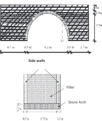
41.2 21.7 31.98 23.2 40.01 41.5 34.4 28.5 0 5 10 15 20 25 30 35 40 45 -6 -4 -2 0 2 4 6 Maximum
live linear load (t/m)
Distance to the mid point of chart(m)
Linear load chart
Fig. 5. Linear load chart.
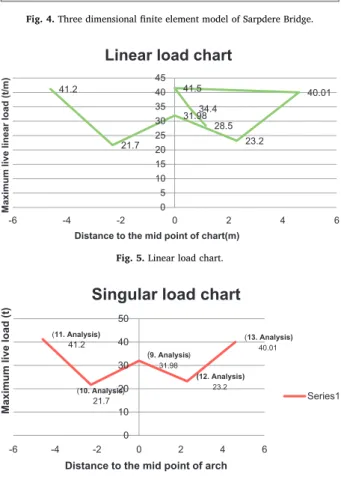
(11. Analysis) 41.2 (10. Analysis) 21.7 (9. Analysis) 31.98 (12. Analysis) 23.2 (13. Analysis) 40.01 0 10 20 30 40 50 -6 -4 -2 0 2 4 6
Maximum live load (t)
Distance to the mid point of arch
Singular load chart
Series1
do not likely reflect the original shape. Still, they do exhibit, at least, the appearance of ancient taste. Before going to description of few exemplar cases, it should be again recalled that the curvilinearity is a feast to the eyes and the brain. The arch is the initial stage of this festivity[19].
The examples above and many more like these examples may have been a source of inspiration for the old masters regarding the different forms of the bridges both in terms of length and aesthetics. In order to determine whether the old masonry bridges are really required to be strengthened or not, thefirst task of us the engineers is to determine the critical loads that will give rise to collapse. The preservation of historical buildings is of growing interest in many countries worldwide. Scientists and engineers perform historical, archeological and in situ investigation to repair, maintain and extend its lifetime. The repair and maintenance of historical masonry structures, generally a structural intervention of the existing structure, are reasons for the need of better understanding of these structures. The basic question arises: What is the carrying capacity, serviceability and the safety degree of the structure before and after intervention? To answer this question is extremely difficult in case of masonry structures, because the determination of material and geometrical parameters is generally uncertain. The architectural design of those buildings lacked a structural design that took advantage of the material properties and that allowed appropriate links between image and construction to be taken into account. Indeed, a detailed evaluation of historical, cultural, architectural and structural aspects is required in order to make correct decisions ([10,18,25]).
We encounter the formation of the computer models related to the experimental studies and investigation of the experiments made by comparing the results obtained from the model analysis and the test results. In the analysis of structures, strength, stiffness and stability characteristics are considered as the three main criteria. The structure should be strong enough to carry the imposed loads, including its self-weight. Large deflections and differential displacements should not occur in the structure, either locally or overall. In this respect, it is also important to know the load history of the structure also. Lack of information about the loading history, strength and stiffness characteristics of the structural materials reduce the accuracy and validity of the results obtained from the structural analysis. In addition, an exact structural analysis should take into account the crack patterns, the crushing phenomena and the actual deformations[2,25].
Before the start of the experimental studies, creating a computer modeling of the test assembly is advantageous. For example, the issues such as determination of the measurements and parameters belonging to the experiment mechanism and experiment samples, determination of the number of the test samples to be tested, determination of the critical points where data will be obtained during the experiment can be possible withfinite-element modeling and the analysis of these models. Thanks to this type of models, minimizing the number of test samples to be tested and due to this, quite considerable economic advantages in terms of material, labor and time can be provided.
The complex heterogeneous material characteristics of masonry, however, limit the validity of conventional methods. Because of the developing techniques in construction, even experimental results become to be an insufficient reference for developing a correct model. Thus, numerical analysis methods of computer based system, have gained increasing importance and started to be the most preferable ones for both engineers and architects in order to perform an inclusively successful study on historical masonry structures. In addition, understanding the failure, designing the strengthening system, creating 3D representation of the structure and static &
Maximum live load (100*MPa)
21.85 19.12 43.7 21.85 19.12 Area affected by distributed load (m2)
Fig. 7. Distributed load graphic.
Table 1
The material properties taken into consideration in theoretical analyses[3].
Material Elasticity module
(N/m2)
Poisson ratio Mass density
(kg/m3)
Stone arch 3.0E9 0.2 1600
Side walls 2.5E9 0.2 1400
dynamic analysis of the material require numerical analysis methods. Especially, seismic behavior of masonry structures represents a very difficult task if handled with traditional methods. Analytical modeling of masonry monuments could also reveal that the load is shared by different structural components and load path followed, which cannot be predicted by conventional analysis methods due to non–linear behavior and intrinsic geometrical complexity of the material (made of blocks interconnected by mortar joints)[25]. There is a lot of work that has been made to this subject. Hatzigeorgiou et al.[17], has modeled historical masonry Artha Bridge withfinite elements, and they have applied linear and non-linear static and dynamic analysis on the model. Boothby [4]has
The total maximum load-carrying capacity of analysis 2 is 32.3 t/m, and the condition of the cracks and fractures on the model due to loading.
The total maximum load-carrying capacity of analysis 3 is 27.5 t/m, and the displacement situation the Y component in the analysis of the node points.
The total maximum load-carrying capacity of analysis 4 is 34.4 t/m, and the total vector displacement situation in the analysis of the node points.
The total maximum load-carrying capacity of analysis 5 is 33.1 t/m, and the deformed state of the model after loading.
The total maximum load-carrying capacity of analysis 6 is 41.5 t/m, and the displacement situation the Y component in the analysis of the node points.
The total maximum load-carrying capacity of analysis 7 is 28.5 t/m, and the condition of the cracks and fractures on the model due to loading.
The total maximum load-carrying capacity of analysis 8 is 28.5 t/m, and the total vector displacement situation in the analysis of the node points.
investigated the behaviors of thefilled arch bridges under the vehicle loads experimentally and with the method of finite elements. He has examinedfive different bridges, and he has analyzed four of these bridges with ANSYS program. Fanning and Boothby[5] have analyzed the Griffith bridge in Dublin, Ireland with ANSYS program as 3 dimensional solid element, and they have done an analysis of the models. Toker and Ünay[26]have tried mathematical modeling techniques on the arch model that has been de-veloped to reflect the general arched stone bridge typology and under various load effects. Ural et al.[22]have stressed the ar-chitectural and engineering properties of historical arch bridges in Turkey.[27]have modeled the concrete-filled steel Beichuan Bridge in the ANYSfinite elements program, and they have performed analytical models and dynamic experimental analyses.
In this study, ANSYS package program was used. In the ANSYS program, there are a large number of ready-made element's modules that may be needed during modeling. With the help of these modules, the single span arch example was modeled by using the ANSYS program.
2. Formulation
ANSYSfinite element program, its geometry or material stress-unit deformation relationship, a variety of iteration procedures are used for the solution of nonlinear systems. If no selection is made, Newton-Raphson method is used automatically. ANSYSfinite element program uses Newton-Raphson method for non-linear analysis solutions. This method, which is known as Newton-Raphson or as the procedure of variable rigidity takes into account the difference in force that will occur at points of node within the system which makes a displacement under the influence of the external loads. The first displacements are found from the rigidity matrix calculated for the position within the structure that has not been deformed. Each subsequent iteration step, the deformed state with Table 3
The distributed loadings.
Analysis results
The total maximum load-carrying capacity of analysis 14 is 0.20 MPa, and the displacement situation the Y component in the analysis of the node points.
The total maximum load-carrying capacity of analysis 15 is 0.36 MPa, and the total vector displacement situation in the analysis of the node points.
The total maximum load-carrying capacity of analysis 16 is 0.10 MPa, and the deformed state of the model after loading
The total maximum load-carrying capacity of analysis 17 is 0.15 MPa, and
The total maximum load-carrying capacity of analysis 18 is 0.22 MPa, and the location of the cracks and fractures on the model due to loading.
compared to Newton Raphson method, fewer matrix processes are used. One of the nonlinear solution methods is the Initial Stiffness method. This method and the Modified Newton Raphson method are similar to each other[6,7,21].
Structural analysis is generally performed in the elasticfield, often following with Finite Element Methods which can be extended to non–linear behavior for more sensitive cases. In the non-linear analysis, the material behaves elastically up to its yield point (at which deformation becomes non-recoverable). But beyond the plastic limit, it continues to withstand its yield stress without taking further stress. The deformation development and the crack patterns are usually indicated by this analysis. It is also possible to carry out non-linear analyses with damage models very useful into the evaluation of the stiffness loss at global and local level. This type of analysis requests the elastic and inelastic properties and the strength of the material. The results that can be gained are the strain behavior, the stress distribution and the collapse mechanism of the structure. In addition to the vertical ones, in presence of hor-izontal actions, a non-linear static analysis can be carried out[24,25].
Structural analysis, which is based on limit behavior of masonry structures, identifies the collapse mechanisms, ultimate stress distributions (at least on critical sections) and load capacities. It is an effective tool for understanding the main aspects of the overall behavior and for evaluating the structural system of the historical masonry constructions. It assumes a rigid no-tension constitutive model for masonry, which implies that the masonry body behaves as an assemblage of rigid elements kept together by compression forces (by plastic zones where all the deformations are concentrated and where the stresses reach the border of the strength domain) (Fig. 1) and crack at regions characterized by tensile stresses[25]. (SeeFigs. 2–7.)
In this approach, if the line of thrust passes outside the entire cross-section, plastic hinges are developed andfinally, a mechanism forms meaning the failure of structure. Plastic behavior of masonry structures is defined by this limit state[25]. As the most useful method in engineering,finite element analysis used to analyze the structure. Through the modeling process, eight nodes and three degrees of freedom per node is used by using ANSYS software SOLID65 type element. Fixed boundary conditions in the foundation sections and sidewalls are considered and the non-linear analysis has been performed based on the Drucker-Prager failure criterion. 3. Application
In the scope of the study, the behaviors of the historical bridge on the Sarpdere Brook located betweenŞahinkaya and Akoluk villages subject to Ulubey Town of Ordu Province under certain loads have been examined. Sarpdere Bridge, which is one of the traditional arched stone bridges of the region has a history of about 200 years. The bridge which has afixed radius single spanned arch was built as a masonry structure. The bridge consists of holding grinder arch parts, side walls andfill material.
In thefigure, longitudinal and transversal appearances of the historic arch bridge are given. The total length from the bridge is 15. 6 m, total arch space and height are 8.2 m and 5.8 m, respectively. The side walls of the bridge consist of stone walls, which are 0.5 m thick.
It is very important that the material properties that should be taken into consideration in the theoretical analyses of the structures that have survived up to the present day such as the historical bridges are determined correctly. Due to the difficulties for the determination of material properties of such structures similar studies on the literature have been examined and material properties taken into consideration have been determined[16]. In this study, the material properties given inTable 1have been used for Sarpdere Bridge. (SeeTables 2 and 3)
In thefinite-element model of the bridge, 7680 pieces of three-dimensional solid elements have been used. The three-dimensional finite-element model of the bridge that has been generated by using the finite-element program ANSYS by using SOLID65 elements is given in Figure.
In the analyses, singular, linear and distributed loads have been used. The behavioral acts of the model against the loads that have been applied have been examined. The graphical representation of the linear load analyses that have been made is as follows.
The graphical representation of the singular load analyses that have been made is as follows. The graphical representation of the distributed load analyses that have been made is as follows. A total of 18 pieces of loading analysis have been made, and the results above have been achieved. 4. Conclusion
Within the scope of the study, non-linear analyses have been made for the general conditions of the arched structures and for the cracks and fractures that might occur under various loads. In these analyses, non-linearfinite element models have been generated with the help of the ANSYS program, and their analyses have been made. In the Model, Solid65-type reinforced concrete element included in the package program has been used. It has been observed that when thefinite element analysis approached the maximum load that the arch bridge can carry, it can no longer reach a solution and the analysis stops. For this reason, the examination of the
behavior of the arch after the maximum load point has not been possible.
The nonlinear static pushover analysis of the mentioned historical arch bridge has shown that, the reachable point can be the maximum load or an earlier point, by using SOLID65 type elements in ANSYS. Therefore, it can be concluded that it is not possible that the modellings made with the ANSYS program will substitute for an experimental model on its own and that they can be used in the examination of the behavior after the maximum loading point under the light of the current studies for that kind of historical arch bridges. Moreover, according to the various applied loadings, the critical points have been determined. The step by step increase of loading resulted cracks and then collapse of the arch. Thus, the collapse load and load application point is recorded as critical loading point.
The variation of load distribution just before the collapse was in a decreasing tendency near the L/2 section, unlike after the L/4 of arch length to the left and right ends. Finally, it has been observed that the loads applied to the right and left of the arch in an equal distance are different, though small, from the filler and the side walls.
Historical masonry structures are generally suffer from man-made (dams, railways, new settlement, vandalism, etc.) and natural (earthquakes,floods, landslides, etc.) hazards. Especially, the ones causing lateral stresses onto the structure should be studied carefully. The structural vulnerability of old masonry against the tension forces necessitates tofind the most effective strengthening technique in order to conserve the historical monuments for a long time. In order to make a correct decision on the strengthening technique for an historical masonry structure, a comprehensive evaluation (structural diagnosis and safety assessment) should be done. The investigation of the site and the existing structural condition, material characteristics, load propagation of the structure, etc. should be carefully carried out for such a study. Moreover, the criteria of choosing a particular and an effective solution should be compatible with the techniques and materials used in the original construction of the monument and respectful to its unique con-ception and historical value.
As regards compatibility problems, it is worth noting that repair techniques were used in the past centuries and the present ones are sometimes only a reproposal of them using modern materials, which can be incompatible with the existing ones. A better knowledge of the traditional techniques and new research to apply them in a modern way will be one of the major issues of the future research of the authors in thisfield. At present, in fact, very few research has been carried out on the behavior of rubble and multiple leaf stone structures before choosing the appropriate repair techniques.
References
[1] Anonim,http://www.orduulubey.gov.tr/sayfa-menu-sarpdere_koprusu-detay-16,109,73,0-1.html, (2013) (15.04.2013).
[2] A.C. Aydin, Restoration of historical structures: material and structural point of view, The 1st International Conference on Sustainable Built Environment Infrastructures in Developing Countries, Vol. 2 12–14 Oct. 2009, pp. 325–336 (Oran, Algeria).
[3] A. Bayraktar, A.C. Altunışık, T. Türker, B. Sevim, Tarihi Köprülerin Deprem Davranışına Sonlu Eleman Model İyileştirilmesinin Etkisi, Altıncı Ulusal Deprem Mühendisliği Konferansı, 2007.
[4] T.E. Boothby, Service load response of masonry arch bridges, J. Struct. Eng. 124 (1) (1998) 17–23.
[5] P.J. Fanning, T.E. Boothby, Three dimensional modelling and full-scale testing of stone arch bridges, Comput. Struct. 79 (2001) 2645–2662. [6] F. Çıngı, Çelik Kiriş Kolon Birleşimlerinin Sismik Tasarım Parametreleri İçin Bir Yazılım, Türkiye Mühendislik Haberleri (2005) 435–2005/1.
[7] F.T. Dede, Tersinir-Tekrarlanır Yükleme Altındaki Betonarme Çerçevelerin Ansys Programı ile Nonliner Sonlu Elaman Analizi, Yüksek Lisans Tezi, Fen Bilimleri Enstitüsü, Selçuk Üniversitesi, Konya, 2006.
[8] A. Dogangun, A. Ural, Characteristics of Anatolian stone arch bridges and a case study for Malabadi Bridge, ARCH’07 – 5th International Conference on Arch Bridges, Madeira, Portugal, September 12–14, 2007, pp. 179–186.
[9] P. Foraboschi, Specific structuralmechanics that underpinned the construction of Venice and dictated Venetian architecture, Eng. Fail. Anal. 78 (2017) 169–195. [10]P. Foraboschi, The central role played by structural design in enabling the construction of buildings that advanced and revolutionized architecture, Constr. Build.
Mater. 114 (2016) 956–976.
[11]P. Foraboschi, A. Vanin, Non-linear static analysis of masonry buildings based on a strut-and-tie modeling, Soil Dyn. Earthq. Eng. 55 (2013) 44–58. [12]P. Foraboschi, A. Vanin, Experimental investigation on bricks from historical Venetian buildings subjected to moisture and salt crystallization, Eng. Fail. Anal. 45
(2014) 185–203.
[13]P. Foraboschi, A. Vanin, Mechanical behavior of the timber–terrazzo composite floor, Constr. Build. Mater. 80 (2015) 295–314. [14]P. Foraboschi, Effectiveness of novel methods to increase the FRP-masonry bond capacity, Compos. Part B 107 (2016) 214–232.
[15]P. Foraboschi, Analytical model to predict the lifetime of concrete members externally reinforced with FRP, Theor. Appl. Fract. Mech. 75 (2015) 137–145. [16]G. Frunzio, M. Monaco, A. Gesualdo, 3D F.E.M. Analysis of a Roman arch bridge, Historical Constructions, 2001 (Guimaraes).
[17]G.D. Hatzigeorgiou, D.E. Beskos, D.D. Teodorakopoulos, M. Sfakianakis, Static and dynamic analysis of the Arta bridge byfinite elements, Arch. Civ. Eng. 2 (1) (1999) 41–51.
[18] P. Hradil, J.Žák, D. Novák, M. Lavický, Stochastic analysis of historical masonry structures, in: P.B. Lourenço, P. Roca (Eds.), Historical Constructions, Ilisu Dam and HEPP Environmental Impact Assessment Report, Ilisu Engineering Group, 2001, pp. 647–654 Retrieved November 3, 2003, fromhttp://www.ecgd.gov.uk/ index/pr_home/pr_ilisu/pr_ilisu-ilisu_dam_project.htm(Guimarães).
[19]E. Karaesmen, Sinan Teması Üzerine Çeşitlemeler, TMMOB, 2008 (in Turkish, 248 pages).
[20]P.B. Lourenço, Computational Strategies for Masonry Structures. Ph.D. Thesis, Dissertation, Delft University of Technology, Delft, The Netherlands, 1996. [21]A. Nuhoğlu, Kablolu sistemlerin Geometrik Nonlineer Statik Hesabı, DEÜ Mühendislik Fakültesi Fen ve Mühendislik Dergisi 1 (2004) 17–38.
[22]A. Ural, S. Oruç, A. Doğangün, Ö.İ. Tuluk, Turkish historical arch bridges and their deteriorations and failures, Eng. Fail. Anal. 15 (2008) 43–53. [23]O. Özer, Assessment of Masonry Arch Bridges by Mechanism Method, MS Thesis, Boğaziçi University, İstanbul, 2006.
[24]A. Romano, Modelling, Analysis and Testing of Masonry Structures, PhD Thesis, Università degli Studi di Napoli Federico II, November 2005 (306 pages). [25]I.N. Sener, An Innovatıve Methodology and Structural Analysıs for Relocatıon of Hıstorıcal Masonry Monuments: A Case Study In Hasankeyf, Msc Thesis, Middle
East Technical University, Turkey, 2004 (167 Pages).
[26]S. Toker, A.İ. Ünay, Mathematical modeling and finite element analysis of masonry arch bridges, G.U. J. Sci. 17 (2) (2004) 129–139.