Incu-Stream 1.0: An Open-Hardware Live-Cell
Imaging System Based on Inverted Bright-Field
Microscopy and Automated Mechanical Scanning
for Real-Time and Long-Term Imaging of
Microplates in Incubator
GÜRAY GÜRKAN 1, (Member, IEEE), AND KORAY GÜRKAN 2
1Electrical and Electronics Engineering Department, Istanbul Kultur University, Atakoy Campus, 34156 Istanbul, Turkey 2Electrical and Electronics Engineering Department, Istanbul University-Cerrahpasa, Avcilar Campus, 34320 Istanbul, Turkey Corresponding author: Güray Gürkan ([email protected])
ABSTRACT Microplate (i.e. microwell plate) is a flat plate that has a specific number of wells to be used as small test tubes in cell-culture studies. In most of the low-budget mammalian cell study laboratories, highly skilled laboratory personnel should determine microscopic changes in microplate well media by taking the microplate outside the incubator and by imaging each well medium under a microscope, with the risk of contamination and reliability degrading. An alternative solution is to use an in-incubator operated live-cell imaging device, which, however, cannot be afforded by low-cost laboratories. In this paper, we present the design, realization, and test stages of a microplate compatible inverted bright-field microscope system that can be used in incubators. The developed system enables real-time and long-term in-incubator imaging of any user-selectable microplate type. The device can capture bright-field microscopic images by using a low-cost CMOS image sensor, an inverted varifocal CCTV lens and an array of light emitting diodes. In addition, by developed two-axial movement stage and image augmenting algorithms, the whole area of a user selectable well (e.g. area of a 6.5 mm diameter well in a 96-well plate) can be automatically imaged without using any other third party software. The long-term performance of the system is tested in incubators with human embryonic kidney and breast cancer cell lines.
INDEX TERMS Open-hardware, bright-field microscopy, live-cell imaging, time-lapse imaging, image stitching.
I. INTRODUCTION
In cell culture studies, microplates are widely used in addi-tion to other vessel types such as flasks, bottles and dishes. A microplate, or a microwell plate, is a flat plate that has specific number of small test tubes so called wells. They are usually manufactured using polystyrene material that gives light transparency for imaging and optical detection purposes, not including UV range. The microplates may involve 6, 12, 24, 48, 96, 384 or 1536 sample wells arranged in a 2:3 aspect ratio. These wells can be either circular or square. The main features of the standard are alphanumeric referencing of the
The associate editor coordinating the review of this manuscript and approving it for publication was Mohammad Zia Ur Rahman.
well locations and 8 × 12 cm footprint. Well-to-well pitch also has a standard value; it is 9 mm for 96-well plates, 4.5 mm for 384-well plates and 2.25 mm for 1536-well plates [1].
During drug discovery applications, dose- and time-dependent effects of candidate agents (e.g. natural com-pounds, chemotherapeutic drugs) on mammalian cells should be analyzed. Live-cell imaging enables the study of such dynamic cellular events. The long-term observations may be achieved with a microscope and a chamber to provide con-ditions that keep the cells functioning and allow observation with the microscope objective [2], [3]. For dose effect analy-sis, microplates are widely used. Appropriate number of cells are seeded and mixed with different doses of drug in separate 2169-3536 2019 IEEE. Translations and content mining are permitted for academic research only.
G. Gürkan, K. Gürkan: Incu-Stream 1.0: Open-Hardware Live-Cell Imaging System
wells of a microplate. Afterwards, the microplate is placed in an incubator that mimics the ideal environmental condi-tions by stabilizing the relative humidity (95 %), temperature (37 ◦C) and CO2 (5 %) levels such as in a human body.
Thus, the dose dependency test can be initiated in a multiwell microplate. After initiation, the long-term effect (12h, 24h, 96h and etc.) of the drug should be observed. In most low-budget laboratories, the observation is achieved by a highly skilled laboratory personnel, by taking the microplate outside the incubator and imaging each well under a microscope. This ‘‘manual’’ observation brings the risk of contamination and degrading of reliability of the drug under test.
Live-cell imaging devices are used for automation of many processes in the molecular biology, chemistry or diagnostic laboratories, which also include the automated observation of drug effects, mentioned above. Various commercially avail-able devices exist [4]–[11], however, these devices come with a high-price option, which makes them less suitable for low-budget microbiology laboratories.
There exist various studies [12]–[21] dealing with the development of low-cost microscopic imaging systems. Parikesit et al. [12] demonstrated the performance anal-ysis of webcam-based microscopy by lens inversion and lens-less imaging methods. They also compared images acquired by inverted-lens and lens-less methods with the ones acquired by a commercial microscope using ImageJ software (Wayn Rasband, National Institute of Health, USA). Lens-less microscopic imaging device realizations are pre-sented in various studies [13], [14]. Such system realizations are becoming popular due to their light-weight, portability and cost-effectiveness. However, as stated in [15], lens-less imaging has drawbacks for in situ cell monitoring due to the short distance (<1 mm) required between the object and the sensor which is not appropriate for imaging of widely used cell culture substrates such as microplates, flasks and Petri dishes.
Kim et al. [15] proposed a low-cost mini-microscope by inverting lens of a webcam (Logitech, Switzerland). To achieve different magnifications (8-60X), they used var-ious cylinders cut from Eppendorf tubes to set desired distances between the inverted lens and CMOS sensor. Image capture and processing algorithms were realized via MATLAB software (Mathworks, Massachusetts, USA). By sharing the same imaging device and additional hardware (e.g. color LEDs for illumination, custom realized parts), Zhang et al. [16] proposed a cost-effective fluorescence mini-microscope in which they used the advantage of the color CMOS sensor for filter-free separation of excitation and emission signals (via offline separation of image RGB channels in MATLAB). Switz et al. [17] proposed a cost-effective inverted-lens mobile phone microscope accompa-nied with a low-cost and manually controlled XYZ stage realization. Walzik et al. [19] proposed a portable imag-ing platform, again, usimag-ing a low-cost webcam (Logitech, Switzerland) and lens inversion method. The platform also involves a simple incubator that enables long-term
live-cell imaging. In addition, to enlarge the field-of-view for image acquisition, they proposed image augmented acqui-sition using an Arduino controlled, cost-effective, motor-ized XY stage. Acquired images were stitched (offline) using ImageJ software. Rajan et al. [20] constructed an upright/invert convertible digital microscope with a mini-bioreactor for long-term simultaneous cell imaging, chemical sensing and electrophysiological recording. They used a com-mercial, manually-controlled XYZ stage for coarse focusing and sample positioning. In addition, they achieved fine focus-ing by usfocus-ing a commercial motorized system that is controlled via Arduino microcontroller and MATLAB based user inter-face. LED based illumination intensity is also controlled from user interface via pulse width modulation (PWM) output of Arduino pin.
In [21], an open-source graphical user interface is pre-sented that enables the control of a robotic XY stage and acquisition of microscopic images from a commercial microscope. In a more recent study, Szymula et al. [22] developed an open-source plate reader (OSP) for auto-mated and multiplexed spectrophotometric measurements. Control of the device is achieved via Python based user interface, a Raspberry Pi microcomputer and low-cost electronics.
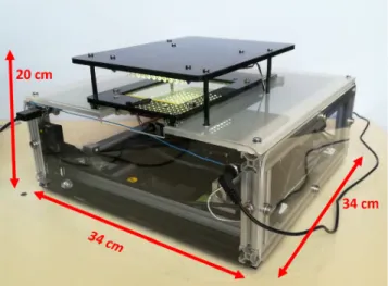
The presented study is focused on realization of an inverted bright-field microscopy type microplate imaging system for low-budget laboratories with the following specifications; a) Device should be open-hardware and easy to be real-ized (by the methods supplied by the authors such as CAD drawings, circuit schematics and etc., b) The hard-ware components of the system should be commercially and widely available with a low-cost (e.g. commercial optical XYZ stages are expensive compared to 3D printer based stages), c) The hardware should involve an open-source-platform microcontroller (such as Arduino), d) The software of the system should also have an open-source-platform (e.g. not MATLAB or similar license required software) and have a user-friendly graphical user interface, f) Device should be suitable for real-time and long-term imaging in an incubator, g) Device should enable remote controlled real-time well browsing, instant and real-time-lapsed image capture modes, h) Device may have a constant field-of-view but should have a remote controlled focus for each well in a specific plate, i) If desired, the device should be able to scan and capture the image of an entire well area, j) The microplate to be imaged should be robustly fed to device in an easy way (e.g. as in high-cost commercial devices). Referring to above specifications, the study in this paper summarizes the development and test stages of an open-hardware inverted bright-field microscope for microplate imaging, named as the Incu-Stream (Fig. 1). The authors, as being electronic engineers, propose easy-to-find and cost-effective mechani-cal and electrimechani-cal components for hardware realization. They also preferred this open-access multi-disciplinary focused journal for a wider audience and possible reproduction community.
FIGURE 1. The final view of the developed Incu-Stream microplate imager hardware and dimensions.
FIGURE 2. Realization of the imaging component: (a) Acrylic layers that are designed in AutoCAD; (b) Commercial motorized lens; (c) Resulting X-tray. CMOS image sensor card can be seen at the bottom; (d) Side view of the imaging component. Note that motorized lens is reversed.
II. REALIZATION OF INCU-STREAM HARDWARE
The hardware is responsible for holding the microplate to be imaged, supplying illumination for imaging and enabling two-axial movement of the main imaging components (the motorized lens and the CMOS sensor) via stepper motors. The electronic control components, buzzer and LEDs are also included in the device hardware.
A. THE IMAGING COMPONENT
The imaging component consists of a CMOS image sensor card, a motorized and inversed CCTV lens, 6 mm thickness acrylic layers and threaded standoffs (Fig. 2).
Authors preferred to use a commercially available and cost-effective USB camera card (USBFHD01M-L21) that is
FIGURE 3. Components of the movement mechanism. Limit switch for Y-axis is placed under Y-tray and thus is not visible.
available with a lens and a 1/2.7 inch color CMOS image sensor option. The sensor (OV2710 Chip) has an active array size of 1920 × 1080 pixels and pixel size is 3µm × 3µm. Module is able to output MJPEG and YUY2 compressed image formats at 30 fps frame rate with 1920 × 1080 pixel resolution. The imaging sensor card is connected to the host user interface via USB protocol.
For imaging, the authors detached the built-in lens and placed a commercially available motorized CCTV camera lens (FG-D14VF2812D3). The CCTV lens has two stepper motors for controlling the zoom and the focus. By reversing the direction of CCTV lens (Fig. 2-b), it is possible to obtain higher magnifications as stated in [12]. Authors fixed the zoom of the CCTV lens to its maximum (by adjusting the zoom (front) lens to its front-most location) and controlled only the focusing (back) lens. This feature is especially desired and enables remote focus control via user interface. B. THE IMAGING COMPONENT MOVEMENT STAGE For imaging of the whole microplate, the imaging component XY movement should, at least, cover an 8 cm × 12 cm area, which is the standard size of microplates [1]. For movement through each axis, stepper motor driven lead screws are used (Fig. 3). Lead screws and accompanying nut translate the rotational movement of the motors to linear movement and they are widely used from large scale industrial applications to indoor devices (especially in 3D printers). Lead screw – nut pairs have a diameter of 8 mm and can be supplied online with 20 cm, 30 cm and 40 cm standard sizes.
The selected bipolar stepper motors are in NEMA 17 stan-dard and have 1.8◦ step resolution (200 steps per route). The two stepper motors are driven via DRV8825 Breakout Board. This board is widely used in motor control appli-cations and gets its name from Texas Instruments’ motor driver chip DRV8825. The chip and thus the breakout board enables (down to 1/32) micro-stepper based driving with only
G. Gürkan, K. Gürkan: Incu-Stream 1.0: Open-Hardware Live-Cell Imaging System
FIGURE 4. Designed circuit schematics of Incu-Stream hardware.
three digital pins, namely Enable, Direction and Step pins. The external motor power supply is also connected to this board. The control of the motor speed, direction and movement steps are achieved by the main micro-controller. The details of electronic control are presented in Section II-C.
Through the studies, × direction is considered as the smaller (letter indexed) and Y direction is considered as the larger (number indexed) dimension of the microplate. The Y-axis tray is the bottom part of the moving mechanism and carries the rest of the moving parts including the X-axis tray, the second stepper motor, lead screw and the imaging com-ponents. The Y-axis tray is designed in AutoCAD (Autodesk Inc, USA) software and cut via 6 mm thickness acrylic layer to ensure robustness. The Y-tray slides on two 8 mm diameter linear rods via 8 mm SC8UU linear bearings that are attached to this tray. Linear rods are attached to the bottom surface of the device via SKT8 linear rail holders. The stepper motor and the limit switch for Y-axis is also attached to the bottom surface of the device. In a similar manner, X-axis tray is designed and constructed from acrylic layer such that it can slide perpendicular to the Y-axis. The linear rail holders of X-axis are attached on the Y-tray surface. All of the mechanical parts (linear rods, rail holders, linear bear-ings, screws, bolts and etc.) can be easily found on the internet.
C. MICROCONTROLLER AND THE CONTROL CIRCUIT The mechanical parts of the device constitute the most of the device volume. However, to control the stepper motors, illumination LEDs and the limit switch inputs, a microcon-troller is required. The microconmicrocon-troller also enables the com-munication between the device and the host user interface. As the microcontroller, the authors selected an easily afford-able Arduino Nano that involves an Atmega328P microchip. This chip is programmable in C language via open-source Arduino IDE platform and Nano’s hardware.
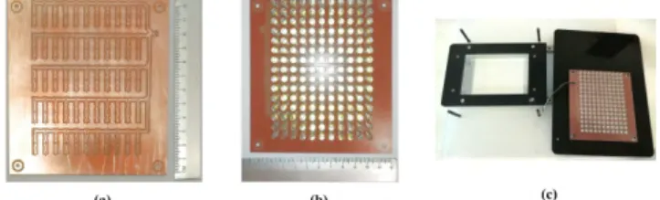
The circuitry is drawn and translated to a PCB design with a commercial software (Isis Schematics and Ares PCB design in Proteus ver. 7.9, Labcenter Electronics, UK). Non-existing packages of Arduino Nano and DRV8825 Breakout boards were drawn and added to schematic library by the authors. The control circuit schematic (Fig. 4) is converted to a PCB layout with 6 cm × 6 cm size (Fig. 5). Prototype PCB was made via PCB engraving machine (MITS Electronics, Japan) from a single sided 20 cm × 20 cm copper board. In addition to microcontroller, the PCB includes a) three SIL-4 type connectors for motor drivers (DRV8825 breakout boards), b) two SIL-3 type connectors for × and Y axis limit switches, c) three SIL-4 type motor connectors, d) two SIL-2 type connectors for illumination and external power supply chassis connector, e) a buzzer for audible warning, f) a large capacitor (2200µF) for suppressing parasitic signals.
FIGURE 5. Overview of input and output connections on realized printed circuit board.
The motor drivers and thus the stepper motor coils are fed via an external +12V / 3A power supply. By an inverter switch configuration, the external power ‘‘ON’’ state is con-verted to transistor-transistor-logic (TTL) zero level (0V). The output is fed to one of the Arduino Nano’s pins (A5) as an input voltage level indicator. The details of this pin will be given in Section 3.
Arduino Nano card’s USB port is connected to host com-puter by which the CPU and board peripherals are powered. Both imaging sensor card and Arduino Nano are connected to host computer via a single USB cable and a small size USB-HUB placed inside the device.
D. FRAMING AND BOX DESIGN
Since the hardware is desired to be an open-hardware type, the authors chose to use easy to find and low-cost materials for the frame and box design. For the size constraint of the device, the authors kept in mind that the device should be able to be fit in a standard sized incubator. All the framing and housing are realized by authors.
Device frame is realized via 20 mm × 20 mm alu-minum sigma profiles. These profiles are robust and have a reasonable weight. In addition, screw-bolts can be easily attached, if required. The sigma profiles can be supplied online and nowadays many online suppliers are able to send the items after cutting them in desired sizes. For whole of the framing, 3 m of sigma profile were used in total (Fig. 6).
Device housing is achieved by covering each side of the frames with acrylic layers. Layer designs are achieved in 2D AutoCAD drawings and cut by CNC laser machine. For left, right, front and rear sides covering, the authors preferred to use 3 mm thickness transparent acrylic material. The bottom side is covered with a 6 mm thickness black acrylic layer. The top side is cut from a 10 mm thickness white acrylic.
FIGURE 6. Realization of device framing via sigma profiles: (a) Ordered sigma profiles; (b) bottom frame; (c) final view after frames attached and movement mechanism installed.
FIGURE 7. Plate holder design via drawer slides and mirror holders. Standoffs are used as a base for illumination layer. The base acrylic surface is the top layer of the device and has 10 mm thickness.
FIGURE 8. Construction stages of illumination layer: (a) Designed and produced PCB for LED array construction, (b) after 5mm white LEDs were soldered; (c) montage and cabling before installation to the device.
On the top surface, authors added a rectangular hole to enable transparency under the plate holder tray.
E. PLATE HOLDER
To enable practical feeding of the microplate, 18 cm length drawer slides and plastic mirror holders are used. The microplate holder tray is designed such that the microplate can gently be fed on to mirror holders (Fig. 7).
F. ILLUMINATION LAYER
Since the device is intended to capture inverted bright-field microscopy images, the imager component and the illumi-nation layer should be located such that the microplate is in trans-illuminated mode. Thus, on the top of the device, the authors designed a final layer that involves 165 LEDs for illumination. The authors selected ultra-bright, 5 mm LEDs (Vishay Semiconductor GmbH, Germany) for illumination. The LEDs cover the entire 8 cm × 12 cm plate area (Fig. 8). When considering the spacing and layout of LEDs, the
G. Gürkan, K. Gürkan: Incu-Stream 1.0: Open-Hardware Live-Cell Imaging System
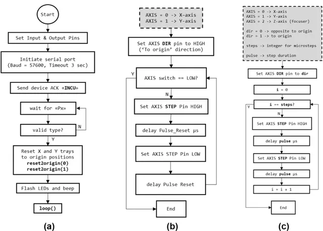
FIGURE 9. The flow diagrams of developed microcontroller algorithms for initiation and motor control: (a) setup() function, (b) reset2origin() function, (c) stepXYZ() function. Required input parameters are given and described in dashed-line boxes.
coincidence of a LED and a well center is desired. However, this cannot be satisfied since the device supports 6 plate types with different well sizes and center coordinates.
Through the development of the illumination layer, authors, first, considered ‘‘scan area dependent’’ LED switch-ing, that is, just to enable groups of LEDs at a scan area; however, the change in active number of LEDs caused unde-sired illumination level differences across distinct ‘‘scan configurations’’. Thus, electrical connection is achieved via 55 parallel-connected branches in which one single branch involves 3 series LEDs. The current switching and limiting is controlled via Arduino Nano’s digital pin and constant biased BC337 transistor, respectively (Fig. 4). The total current is empirically adjusted to 200 mA (yielding to 3.6 mA for each LED) to avoid over-exposed or under-exposed captures within selectable exposure range of the CMOS sensor. LEDs are connected to the main controller circuit via two wires and a SIL-2 type connector. LEDs and motors share the same external power supply.
III. MICROCONTROLLER AND USER INTERFACE PROGRAMMING
In this section, the developed algorithms for microcontroller (Atmega328P on Arduino Nano) and user interface (Python on host computer) are presented. The user interface is devel-oped in Python language and Qt-Designer platform whereas
the microcontroller is programmed via Arduino’s IDE plat-form (Sketch) in C language. The flow diagrams, command table and screenshots are also presented.
A. MICROCONTROLLER ALGORITHM: MESSAGES & IMAGING COMPONENT CONTROL
As mentioned earlier, the main duty of the microcontroller is to control stepper motors, illumination and buzzer. The stepper motors are used in two-axial movement and image focusing and driven via DRV8825 motor drivers. Illumination is required for ‘bright-field microscope’ mode image acqui-sition and generated via array of white LEDs. The buzzer is used to generate auditory warning and acknowledge. The microcontroller receives and transmits messages (i.e. com-mands) to the host user interface via serial port connection established via USB port. Through code development, in addition to the standard setup() and loop() void type func-tions of Arduino IDE, the authors developed various custom functions for precise control of the hardware.
After the power-up, the input-output (I/O) pins and serial connection is initiated in the setup() function (Fig. 9). The baud rate is selected as 57600 bps. For finite duration port response, the timeout for serial connection is set to 3 seconds. After an audible acknowledge ‘beep’ to the user via buzzer, microcontroller transmits ‘‘INCU’’ acknowledge message and starts listening to serial port for ‘plate type selection’
message. Plate type can be selected via ‘Px’ string command where × is an integer. For × values from 0 to 4, one can select 6, 12, 24, 48 and 96-well plates, respectively via serial port. By receiving the ‘‘Px’’ message, the algorithm assigns the global variable type to its corresponding value (e.g. 0, 1 or 4). Until the reset message is received, the plate type value and thus the plate type cannot be changed.
After successful type selection, the × and Y trays are reset to their origins. For reset operation, reset2origin() function is developed. This function expects a single argument which is the axis index. Through the whole control algorithm, for X, Y and Z (focuser lens) axes, the indices of 0, 1 and 2 are used, respectively. The outputs of limit switch (for × and Y axes) modules are read via microcontroller corresponding input pins (Fig. 4) continuously and the motors are stopped if LOW output level is detected.
Following the resetting of × and Y trays, the LEDs are flashed and an auditory message is generated via buzzer. After these events, the setup() function ends and the micro-controller enters to the loop() function, leaving the LEDs in ON state.
For the device to be able to reset the trays, thus to drive the stepper motors, an external (12V) power supply should always be connected. To prevent step loss and/or operation without external power supply, the algorithm always checks the existence of external power voltage before enabling motor coils. This is achieved referring to aforementioned ‘‘inverter configuration’’; if external power is ON, then the resulting output of the inverter circuitry will be in LOW level and vice versa. The output of the inverter circuitry is fed as an input pin to Atmega328 chip (Fig. 4). The developed checkPower() function reads the state of this pin and enters to an infinite ‘‘while’’ loop as long as this pin is HIGH. The infinite loop is accompanied by beeping generated via 100 ms period square wave output that is connected to the buzzer pin. The checkPower() function calls are not shown in flow diagrams of this manuscript.
After the plate type selection, the loop() function is started and the system trays are at their origin. In the loop() function, decodeMove() function is called. This function decodes pre-defined messages to valid movement task codes and global variable assignments as shown in Table 1.
All 165 LEDs are ON at the beginning of a live-view or image acquisition cycle (that includes image cap-turing of selected wells with desired sub-grid configuration). There exists enough time period (>5 seconds) for the LEDs to settle at the beginning of a new capture cycle. The total time that the LEDs stay ON in an image acquisition cycle depends on the scan configuration (e.g. number of wells and sub-grids).
1) MOVING TO A SPECIFIC WELL
In the starting ‘‘origin state’’, the imaging component can only be moved to a desired well or the current plate type can be reset (X and Y trays are also reset to their origins). Well addressing is established by ‘‘XmYnn’’ string message.
TABLE 1.Messages and assigned task ids that can be passed through decodeWell() function.
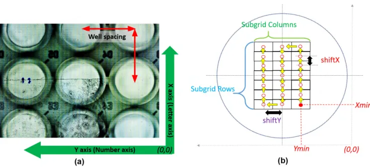
Here, as mentioned earlier, × axis is the letter-indexed and Y axis is the numerical-indexed axis of the plate. For exam-ple, by sending the message ‘‘X3Y09’’, the imaging com-ponent can be moved to well C-9. Since the authors chose (8 × 12) 96-well plate as the most intense plate type, m may have letters from ‘‘A’’ to ‘‘H’’ whereas n should have values from ‘‘01’’ to ‘‘12’’.
The first movement after origin state is achieved by first advancing to well A-1 and then by achieving the desired well movement. For each plate type, origin to A-1 movements and well-spacing microsteps should be calibrated and entered by the programmer. Thus, calibration requires three global variables to be defined: × and Y microsteps from the origin and well-spacing of the microplate. These parameters are defined for five plate types in five element global arrays, namely, X_offset, Y_offset and spacing. Movements for all axes are achieved using developed stepXYZ() function. 2) WELL BROWSING AND FOCUSING
After any first movement from origin state to a target well, the imager component can be moved for well browsing (jogging) in incubator.
Stepper motor type (200 steps per route), motor driving method (1/32 micro-stepping via DRV8825) and screw pitch size (8 mm per route) determines the mechanical resolu-tion of XY movement stage (200×32/8 = 800 steps/mm). In addition, backlash should also be considered when plan-ning precise and repeatable movements while using low-cost materials. Backlash introduces a dead band when the direction of travel is reversed. Thus, backlash can be sup-pressed by adding specific number of steps to the next movement if the movement direction is reversed. For the proposed system, mechanical backlash in XY movement stage is empirically determined by applying repeated reversed movements to imaging component and observing the location changes of a reference object captured with the camera under LED illumination.
The messages ‘‘xp’’ and ‘‘xn’’ result in globally predefined (±xstep) movements in X-axis whereas ‘‘yp’’ and ‘‘yn’’ mes-sages result in (±ystep) movements in Y-axis. For both × and
G. Gürkan, K. Gürkan: Incu-Stream 1.0: Open-Hardware Live-Cell Imaging System
FIGURE 10. Ultra-wide-field captured image and sub-grid capture algorithm: (a) Well D4 of a 96-well plate was selected for a 53 rows × 41 columns sub-grid capture mode. The resulting image has a wide field of view and reflects the ‘‘bottom view’’ of the microplate. Rectangular borders of each augmented image can be seen. (b) Motion path of developed sub-grid capture algorithm for 7 rows × 3 columns capture mode.
Y axes, jogging is set to 100 (micro-) steps (1x = 1y = 125µm). This value is optional and can be changed in code file. User controlled XY movements enable browsing of the microplate wells (or any other type flask surface) in ‘‘Live View’’ mode that is presented in the next section.
Being different from × and Y axes, Z-axis movement is achieved via motorized lens system. Accuracy of motorized focusing (i.e. back lens movement) is determined by applying alternating up-down lens movements and testing for focus consistency. After various tests, backlash in the focusing mechanism is avoided by allowing only one sided (down-wards) movement of the focusing lens and referencing from the initial (top) mechanical limit if a ‘‘reverse’’ movement is required. By four messages {‘‘zp’’,’’zn’’,’’Zp’’,’’Zn’’}, coarse (zstep = 200 steps = 40µm) and fine (zstep_fine = 40 steps = 8µm) lens movements can be achieved. The focus lens has 10 mm movement range.
Well browsing and focusing features enable in-incubator observation of a microplate. As will be mentioned in the user interface section, the user is also able to take snapshots while browsing through the wells of a microplate in incubator. These Incu-Stream features are similar with the ones in (high-cost) commercial live-cell imaging devices.
3) SUB-GRID CAPTURE CONFIGURATION
As will be mentioned in the user interface section, the system can be configured to capture images of well(s) via mechanical XY scanning with user selectable number of sub-grids. This results in an enlarged field-of-view without losing spatial (optical resolution) using the low-cost CMOS image sensor, similar to the system proposed in Walzik et al. [19]. Sub-grid configuration is achieved by the message ‘‘rxxcyy’’,
where xx is the number of rows and yy is the number of columns for sub-grid capture mode. For example, the mes-sage ‘‘r05c07’’ will setup a ‘‘5 rows by 7 columns’’ aug-mented image, being independent of the plate type selected. Here, each element of the augmented image actually has 1920 × 1080 pixels. However, the resulting image size can be reduced by down sampling (decimation) factor (fs) that is initiated and selectable in the user interface algorithm. As an example, the image in Fig. 10-a is acquired with 53 rows × 41 columns sub-grid capturing with a decimation factor of 0.1. Note that the images are captured as the bottom view of the well.
4) SUB-GRID CAPTURE - MOTION CONTROL
To start capture with a specific sub-grid configuration in the current well (after ‘‘XmmYnn’’ and ‘‘rxxcyy’’ messages), message ‘‘G’’ should be sent to the microcontroller. After the microcontroller receives the message, the × and Y trays are reset to origin and driven back to Xmin, Ymin coordinates for initiation of sub-grid capture process of target well. The microcontroller then sends ‘‘O’’ message and starts to wait for ‘‘C’’ message, which is sent in sub-grid capture mode by the user interface. After ‘‘C’’ is received, the imaging compo-nent is moved to next planned sub-grid address (Fig. 10-b). After all addresses are processed, the microcontroller sends a ‘‘W’’ message to the host interface and calls decodemove() function again. User interface is responsible for CMOS image sensor control, focus adjustment, capturing, augmenting and saving the images to host computer’s storage.
By the message ‘‘F’’, the plate type can be reset by restart-ing (resettrestart-ing) the microcontroller and recallrestart-ing the setup() function.
FIGURE 11. Snapshot of Setup tab in developed Incu-Stream user interface.
5) SUB-GRID CAPTURE – DURATION
Total duration of a whole well capture depends on the selected sub-grid configuration and the plate type. However, for a fixed sub-grid configuration, capture duration for a single well is independent of the selected plate type. The duration is determined by deliberate delays introduced after each end of stepper motor movement to ensure mechanical settling and stable image capture. The duration of delays are determined by various tests and optimized for stable and rapid image capture.
For 5 × 5 sub-grid configuration, single well capture dura-tion is measured as 21 seconds and for 10 × 10 sub-grid configuration, it is measured as 86 seconds. Thus, multi-grid capture speed can be stated as ∼0.85 seconds/grid.
B. USER INTERFACE PROGRAMMING
The development of Incu-Stream user interface is realized using two main platforms. The first is the Qt-Designer (Qt Group) software that is used for graphical user interface development. This program allows drag-and-drop design and preview rather than coding to ensure the user interface works as intended. The resulting file has (∗.ui) extension and can be converted to a Python script using pyuic4 command of PyQt4 module. The gui file can be run via Python inter-preter, however, without callbacks. The second platform is the Python interpreter and thus another Python script. Authors used Spyder 2 IDE platform for user interface and control algorithm development. The user interface can run on any operating system (Windows, IOS or Linux) if required Python modules are installed.
The user interface consists of five selectable tabs; Setup, Acquisition, Live View, Browser and Logger. After the main Python script is run, the interface starts searching available COM (or /dev/tty in Linux) ports and listens for ‘‘INCU’’ acknowledge. If acknowledge is received from one of the COM ports, the user interface starts in Setup tab (Fig. 11) with ‘‘Device connected’’ status message which is shown at
FIGURE 12. Snapshot of Acquisition tab in Incu-Stream user interface.
the bottom of the user interface. If not, status message is ‘‘No device connected’’ and the user interface goes into the passive state. The script also checks whether a folder named ‘‘Incustream’’ exists in root directory and, if not, generates this folder.
In the Setup tab, user has to select the proper microplate type and, if required, the sub-grid imaging configuration. For the current version, user can select the number of rows and columns for sub-grid imaging. Since the resulting images will have very high pixel sizes, user can also select decimation levels of 1, 0.75, 0.5, 0.25 and 0.1 for smaller sized images. User can also supply required fields for e-mail alerts such as user name, password and SMTP server. E-mail alert is useful for automated long-term acquisition modes.
After the plate type selection, the widgets in Acquisition and Live View tabs are enabled. In Acquisition tab (Fig. 12), user can enable/disable the automated image acquisition of a well by left mouse clicking. The clicking is programmed to work on toggling mode. The disabled well becomes red, whereas enabled well becomes green. User can enter information about a well, such as cell name, compound, cell concentration and etc. into ‘‘Well Properties’’ label group. In Acquisition tab, user can also adjust the acquisition mode via ‘‘Time Lapse Acquisition’’ group box. If ‘‘Time Lapse Acquisition’’ mode is selected, two additional knobs will be enabled. The total duration of the repeated image acquisition (in hours) should be adjusted via ‘‘Duration’’ knob. The repeat period (in minutes) should be adjusted via ‘‘Repeat Period’’ knob. Completed image acquisition progress per-centage is updated respect to each well (Current) and each repetition (Overall).
By pressing the start button, user can start automated well imaging. Acquired images during automated acquisition is saved in a folder that is automatically generated by the user interface control algorithm. If single (non-repeating) acquisi-tion is selected then the captured image files will be named corresponding to the scanned well name (A1, A2 and etc.) and will be saved in a folder named ‘‘SM_YY_HH_MM_SS’’
G. Gürkan, K. Gürkan: Incu-Stream 1.0: Open-Hardware Live-Cell Imaging System
FIGURE 13. Snapshot of Live-View tab in Incu-Stream user interface.
FIGURE 14. Snapshot of Browser tab in Incu-Stream user interface.
where ‘‘SM’’ is the abbreviation for ‘‘single mode’’ and the rest of the string is the date-time sequence that the capture was started. If repeating (Time Lapse) acquisition is selected, the index of repetition is also added to image file names (A1_1, A1_2 and etc.) and they will be saved in a folder named ‘‘RM_ YY_HH_MM_SS’’ where ‘‘RM’’ is the abbre-viation for ‘‘repeated mode’’. After a single mode is finished in a repeated mode acquisition, a count-down timer is started and printed in progress group-box. All the events during automated microplate imaging are recorded as separate lines and visible through the Logger tab.
In Live View tab (Fig. 13), real-time imaging of a plate is possible. Depending on the selected well type, user can start live view session and observe pre-defined wells by using the combo-box and ‘‘Go’’ button that are located in ‘‘Navigator’’ group. For this state, CMOS camera is ‘‘on’’ until end of live view session. Image is refreshed in every 1/30 seconds by using a QTimer() object. Image scale bar (100 microm-eters) is also shown at the bottom-right position. Image acquisition parameters such as brightness, contrast,
satura-FIGURE 15. Determination of field-of-view and resolution: (a) Calibration glass is aligned with horizontal axis (Incu-Stream image); (b) Calibration glass is aligned with vertical axis (Incu-Stream image). Unit length is 100µm and corresponds to 280 pixels in both horizontal and vertical directions; (c) Yeast cells and resolution inspection (Incu-Stream image). Minimum distance is determined excluding budding cells; (d) Reference image acquired from conventional microscope system (IX71 Microscope and DP71 Microscope Camera, Olympus). Presented 1920 × 1080 image is cropped from a higher (4080 × 3072) image to ensure pixel consistency (scale bar = 100µm).
FIGURE 16. The acquired and zoomed images from well C4 of a 96-well plate. The image is acquired after well is filled with a drop of drinking water and a finger is tipped into it. The sub-grid size is 11 columns and 19 rows with an image decimation factor 0.5. The zoomed image has an original pixel size of 960 × 540 due to decimation factor whereas the acquired image size is 10560 × 10260 pixels. The imaged cells are epithelial cell drops due to finger tipping.
FIGURE 17. Incu-Stream test stage in a CO2incubator: (a) Location of host computer for user interface; (b) inner view of incubator after Incu-Stream is installed on the top shell; (c) Feeding 96-well plate on to the plate holder while in the incubator.
tion, exposure, pixel gain and sharpness can be adjusted via corresponding sliders. User can also browse freely with-in a
FIGURE 18. Incu-Stream images of MDA-MB-231 cancer lines via ‘‘Get snapshot’’ command in Live-View tab. Image size is 1920 × 1080 and overlaid scale bar size is 100µm: (a) Control group; (b) Target group in cisplatin added media.
FIGURE 19. Acquired 10560 × 9180 time-lapse image examples from first incubator test. Time interval between selected images is 4 hours. These images verify the well alignment consistency of the device for long-term captures in the incubator.
specific well by using the navigator buttons and can adjust the required focus via Coarse and Fine Focus sliders. Each focus position for a specific well can be saved to be recalled during automated imaging mode. The lens origin can be reverted via ‘‘Reset to Origin’’ button. If desired, user can take a snapshot of the live view. The image is saved as ∗.JPG file whereas the file name is automatically assigned as the current date and the number of snapshots till program was started.
All captured images and repeated measurements can be analyzed via Browser tab (Fig. 14). The algorithm for this tab generates a folder list referring to ‘‘Incustream’’ folder. User can browse single (SM_...) and repeated (RM_...) mode image folders. In addition, user can easily progress through repeated acquisitions (A1_1, A1_2 and etc.) for a single well (A1) by using a slider. Changing the slider updates the image acquired at the corresponding cycle number.
IV. CALIBRATION
A. CALIBRATION OF IMAGE SCALE
The images are acquired with highest imaging area (1920 × 1080) with a fixed (lens) zoom distance for simpler calibration. If smaller sized images are desired, captured images are decimated rather than adjusting lower resolution
FIGURE 20. Detailed analysis of well image (D4) that was obtained just after 1 hour (in the second capture cycle) from initiation of the first incubator test. General image view gives useful information about the cell states; however, acquired image has a poor focus as shown in zoomed view.
FIGURE 21. Incu-Stream test stage in a non-CO2and dry incubator: (a) Cabling and location of host computer; (b) inner view of the incubator with lid open.
modes of CMOS sensor. This is due to fact that the latter case is achieved via sensor based image cropping which directly decreases the image area and thus yields to a different image scale.
For determination of field-of-view, authors used a 0.1 mm DIV microscope eyepiece micrometer glass (LeeTun, China) with a diameter of 20 mm. By analysis of captured images (Fig. 15-a, Fig. 15-b), 0.1 mm (100 µm) length is mea-sured as 280 pixels in both vertical and horizontal directions. The chosen lens is not corrected for geometrical aberra-tions since no serious defect is observed in scale lines. For the inversed lens configuration, horizontal field-of-view is (1920 / 280) × 0.1 = 685µm whereas vertical field-of-view is (1080 / 280) × 0.1 = 385µm.
G. Gürkan, K. Gürkan: Incu-Stream 1.0: Open-Hardware Live-Cell Imaging System
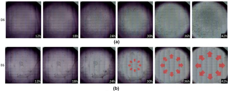
FIGURE 22. Selected time-lapse images of wells D6 and E6 acquired during non-CO2and dry incubator: (a) in well D6, most of the cells stay attached on well surface; b) in well E6, the cell death is increased by cisplatin and the floating cells are drifted from well border by the evaporating media.
B. MAGNIFICATION AND RESOLUTION
Considering the imaging area of OV2710 CMOS sensor (5856 µm × 3276 µm) and the measured field-of-view (685µm × 385 µm), the total magnification of the inverted lens can be calculated as ∼8.5X. In microscopy terms, a sim-ilar circular field-of-view (e.g. with 685µm diameter) would be obtained using a standard (10X, 18 mm field number) ocular and ∼26X (= 18 / 0.685) objective lens [23].
For estimation of optical resolution, authors observed (Fig. 15-c) unicellular Saccharomyces cerevisiae cells, which are known as Baker’s Yeast cells (see Appendix). As a refer-ence, the same group of cells are also imaged (Fig. 15-d) with a conventional microscope (IX71, Olympus) at 20X objec-tive and dedicated camera (DP71, Olympus). The developed imaging system is able to distinguish cells that have more than ∼1.8µm spacing (Fig. 15-c). This resolution is lower than that of the conventional microscope (Fig. 15-d) however it is adequate for cell culture studies [15].
C. CALIBRATION OF IMAGING COMPONENT MOVEMENTS
The offsets and well spacings are translated to corresponding micro-steppping values for 6, 12, 24, 48 and 96-well plate types. In addition, referring to image scale test, the vertical and horizontal microsteps for sub-grid capture mode is itera-tively adjusted.
V. DEVICE TESTS AND VALIDATION
The initial device tests were focused on reliability of the user interface and the mechanical control in room temperature. The user interface is installed on a laptop with 64 bit Windows 10 OS, Intel Core i7-5500 2.4 GHz CPU, 8 GB RAM and 320 GB 7200 RPM hard-disk.
The manually focused image in Fig. 16 was obtained from well C4 of a 96-well plate, with 0.5 image decimation factor
value. The sub-grid size was adjusted to 11 columns and 19 rows, yielding to an image with 10560 × 10260 pixel size. The image is focused referring to lower layer of the plate thus well border line that is placed on higher layer of the plate has an out-of-focus blur.
For human cell studies, incubators are used in 37◦C tem-perature, 95 % humidity and 5 % CO2levels. Thus, device
stability should also be tested under these conditions, espe-cially for long-term observations.
Various tests were achieved with Human Embryonic Kid-ney (HEK) cells and MDA-MB-231 cancer cell lines in a 96 well-plate (TPP 92096, TPP, Switzerland) after proper preparations (see Appendix).
In the first test (Fig. 17), the device is placed in a CO2
incubator (Nüve EC160, Nuve, Turkiye). After 15 minutes, well browsing property of the device is tested via Live-View tab and snapshots are acquired (Fig. 18). Presented images are the flat-field corrected versions of the captured images.
For time-lapse mode testing, well D4 was prepared as the control and well D5 as the target cancer cell group. The total time of acquisition was set to 12 hours whereas the interval between each capture cycle was set to 60 minutes. In addition, the decimation factor was set to 0.5 and sub-grid size was set to 17 rows × 11 columns. Thus, for the long-term testing, the device would acquire two well images per one hour, yielding to 24 RGB images. Image dimension is 10560 × 9180 and sizes are detected to be in 37 MB – 39 MB range.
The timing of automated cycle initiation and well align-ment consistency between images (Fig. 19) were satisfactory in the incubator test. Detailed inspection of images, however, revealed poor focusing (Fig. 20) at all images except the manually focused (initial) well image.
At the beginning of image acquisition tests, the live (can-cer) cells are adhered (attached) to the surface of the plate. For this state, the distance between the lens and the cells is at
FIGURE 23. Selected time-lapse images of wells D6 and E6 acquired during non-CO2and dry incubator: (a) in well D6, most of the cells stay attached on well surface; b) in well E6, the cell death is increased by cisplatin and the floating cells are drifted from well center to well border by the evaporating media.
FIGURE 24. Snapshots acquired from video recording (total length = 15 seconds) during C.elegans movements. Video is captured via screen recording software (OBS Studio) while Incu-Stream Live-View mode was enabled. Video frame rate is 30 fps.
its minimum. Depending on the media, cells may continue to spread across well surface or, cell death may begin. The cell death is accompanied by increase in detached and floating cells in well media [24]. This results in loose of focus since detached cell – lens distance may be increased. The detaching of death cells from well surface is discriminative and used in commercial products [25].
After a couple of additional incubator tests, the main reason of the focus loss is detected to be the backlash that exists in lens movement mechanism and of which effect was also increased in the incubator by temperature. To overcome this problem, the well specific focusing algorithm is updated by referencing the lens movement to the origin of the movement mechanism at the beginning of each acquisition cycle.
Another long-term image acquisition test (Fig. 21) was started in a non-CO2and dry incubator (Nüve EN055, Nuve,
Turkiye). Cells were seeded in two wells, D6 being the control and E6 being the target. The acquisition interval was adjusted to 30 minutes and the total duration was set to 48 hours. With no decimation (fs=1), the sub-grid size was selected as 13 rows and 7 columns, yielding to a target image dimension of 13440 × 14040 pixels.
Referring to the analysis of the acquired images, the image sizes are detected to be in the range 100 MB – 115 MB for well D6 and 58 MB – 95 MB for well E6, respec-tively. By analysis of time-lapse images (Fig. 22, Fig. 23), important features can be seen. First, the increase in image intensity levels starting from well centers can easily be
G. Gürkan, K. Gürkan: Incu-Stream 1.0: Open-Hardware Live-Cell Imaging System
TABLE 2. Cost table of used items.
detected. This is due to evaporation of well media in the dry incubator. Second, it can be seen that the control cell lines (D6) stay attached to the well surface (Fig. 22–a), whereas floating target cell lines (E6) are drifted from well center to well border (Fig. 22-b) due to vaporizing media.
For focus quality analysis, images are cropped and con-trast stretched by mapping intensity values 15 - 135 to 0 – 255 range, respectively (Fig. 23). The analysis reveals that the focus adjustment for each well had finally became satisfactory via modified focusing algorithm.
To demonstrate the real-time usage of the developed sys-tem, authors observed the movements of C. elegans(see Appendix). During observations, a screen capture software (OBS Studio) is used for video recording at 30 frames per sec-ond (fps) rate. After appropriate focusing, authors managed to capture various C.elegans movements (Fig. 24).
VI. DISCUSSION and CONCLUSION
Authors presented the design, realization and operation of an open-hardware inverted bright-field microscopic imag-ing system especially designed for microplates. In order to demonstrate drug (cisplatin) induced cell viability loss and detachment, the proposed system is tested via cancer cell lines in a commercial incubator for long-term (> 48 h).
Being different from the previous studies, the proposed system can be used for live-cell imaging simultaneously with its own open-source user interface without any other third party software. Even unskilled laboratory personnel can observe and capture the microscopic images of a microplate located in an incubator by browsing through wells in an autonomous fashion, using real-time well browsing and snap-shot options. These features make the device suitable and important for all low-budget microbiology and cell culture laboratories, even for undergraduate education.
Hardware realization requires a low budget as shown in Table 2. However, considering the device facilities of authors, realization of the hardware may require additional service cost such as PCB manufacturing and laser CNC
cut-ting. In addition, alternative packaging materials (e.g. alu-minum) can be used as proposed in [22].
Color CMOS sensor is preferred due to intended (future) versatility of the device for color-discriminative cell culture studies such as fluorescent imaging [as in 16] that will be achieved by modification of illumination layer (e.g. using red, green and blue LEDs).
Low-cost color CMOS sensor is equipped with a motor-ized varifocal CCTV lens rather than its own fixed-focus lens as proposed in [15]–[17], [19], [21]. This modification increases the working distance and enables users to adjust focusing, as proposed in [20] and high-cost commercial devices [5]–[11], even if the device is in incubator.
The system is especially developed to be robust and com-patible with microplates that are widely used in cell culture studies. The proposed augmented imaging method shows similarity with the one presented by Walzik et al. [19]. Authors achieved improvements in mechanical scanning and focusing which were reported to be inaccurate in [19] for long-term imaging. In addition, rather than offline pro-cessing, the system can automatically create wide-field bright-field microscopic images by scanning and stitching 685µm × 385 µm-sized rectangular sub-grids with a mini-mum (optical) resolution of ∼1.8µm. Preferred movement stage realization is more cost effective than commercially available optical XY stages as used in [20].
Thanks to developed user interface, autonomous time-lapse microscopic imaging of selected wells can be realized with initially configured sub-grid configurations and cap-ture intervals. Total duration of the time-lapse can be up to 72 hours. Constructed images can be browsed in Incu-Stream’s image browser (Fig. 14), which enables practical scrolling and progress analysis of time-lapse images acquired from a specific well.
Acquired and saved images can be processed further using a third party software as in [12]–[20] and [22]. The acquired image size may be large for increased sub-grid row/column numbers. Such images may require additional CPU process-ing speed and memory for modification.
In proposed version of Incu-Stream system, authors fixed the front lens distance of the CCTV lens to its maximum, thus, disabled the zoom (out) feature of the lens. Front lens distance can be decreased to a certain level, yielding to decreased magnification (= projected image length on sensor / object length) and wider field-of-view. However, this requires not only the modification of the hardware (addition of a fourth DRV8825 for zoom stepper motor control) but also the update of the codes (of Arduino and user interface) and re-calibration of field-of-view for each zoom (out) value, as well. This is planned and recommended update feature of this system.
The final versions of CAD drawings, controller PCB layout files, codes and recorded (real-time) videos are shared in a public link [26].
Addition of new (e.g. image processing) algorithms or even new tabs to the proposed (initial) form of the Incu-Stream user interface is possible thanks to open-source Python
pro-gramming language and its additional libraries as stated in [22]. Histogram equalization, flat-field (background) cor-rection, (RGB) color channel separation, auto-focusing, focus (z-axis) stacking options can be added as new software features without making any changes to the proposed Incu-Stream hardware. For aforementioned reasons, the authors suggested the initial version of the system in the manuscript title.
APPENDIX
MDA-MB-231 breast cancer and HEK293 normal epithelial cells (American Type Culture Collection, Manassas, USA) were used in device tests. The MDA-MB-231 breast cancer cells were maintained in RPMI medium and HEK-293 cells were cultured in MEM-Eagle medium (PAN Biotech, Aiden-bach, Germany) supplemented with 2 mM L-glutamine, 10% fetal calf serum, 1% non-essential amino acids (Biolog-ical Industries, Kibbutz Beit-Haemek, Israel) in the presence of 5% CO2in a humidified atmosphere at 37◦C.
Each cell line was seeded at a density of 10.000 cells/well in a 96 well plate, incubated overnight to ensure cell attach-ment to the well surface. Following incubation, target wells were treated with cisplatin (30µM) in order to demonstrate drug induced cell viability loss and detachment.
For observation of Saccharomyces cerevisiae cells, active dry Baker’s Yeast was purchased from market and 0.1 mg yeast was dissolved in 1 ml sterile distilled water. Solu-bilized yeast solution was diluted 1:1000 by sterile dis-tilled water. 100 µl of dilution was dropped on the lam center and covered by lamella to be observed in Incu-Stream. Lamella is placed on top of a reversed microplate cover.
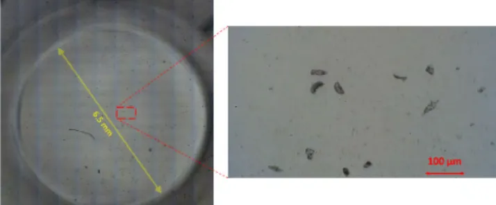
One square centimeters of nematode growth medium (NGM) plates with Caenorhabditis elegans (C. elegans), N2 stained to fresh NGM plates with Escherichia coli (E. coli) bacteria strain OP50 at 20◦C. Following 4 days of incubation period, C. elegansplate is observed for nematode movement in Incu-Stream’s Live-View mode.
ACKNOWLEDGMENT
Authors wish to thank Prof. Ajda Coker-Gurkan (Molec-ular Biology and Genetics Department, Molec(Molec-ular Cancer Biology Laboratories, Istanbul Kültür University, Istanbul, Turkiye) for precious support through cell supplies, prepa-ration, incubator tests and user interface critics. They also thank Onder Parlak (Faculty of Architecture, Istanbul Kültür University, Istanbul, Turkiye) for his suggestions and support through the mechanical realization of the device hardware.
REFERENCES
[1] S. Ye and I. Day, Microarrays and Microplates: Applications in Biomedical Sciences. Oxford, U.K.: BIOS Scientific, 2003.
[2] M. E. Dailey, G. S. Marrs, and D. Kurpius, ‘‘Maintaining live cells and tis-sue slices in the imaging setup,’’ Cold Spring Harbor Protocols, vol. 2011, no. 4, p. 105, Apr. 2011. doi:10.1101/pdb.top105.
[3] A. Khodjakov and C. L. Rieder, ‘‘Imaging the division process in living tissue culture cells,’’ Methods, vol. 38, no. 1, pp. 2–16, Jan. 2006. doi:10. 1016/j.ymeth.2005.07.007.
[4] Commercial Cell Imager Systems. Accessed: Feb. 23, 2019. [Online]. Available: https://www.biocompare.com/pfu/10242895/soids/2254288/ Microscopes_and_Cell_Imaging_Systems/Cell_Imaging_System [5] E. BioScience. (2016). Real-Time, Quantitative Live-Cell Analysis.
IncuCyte ZOOM System. Accessed: Feb. 23, 2019. [Online]. Available: https://www.essenbioscience.com/media/uploads/files/8000-0333-E00-IncuCyte_ZOOM_brochure.pdf
[6] Etaluma. Lumascopes. Accessed: Feb. 23, 2019. [Online]. Available: http:// www.etaluma.com/products/about-lumascope-fluorescent-microscopes/ [7] Biotek. Cytation 5 Cell Imaging Multi-Mode Reader. Accessed:
Feb. 23, 2019. [Online]. Available: https://www.biotek.com/products/ imaging-microscopy-cell-imaging-multi-mode-readers/cytation-5-cell-imaging-multi-mode-reader/
[8] Biotek. Lionheart FX Automated Microscope. Accessed: Feb. 23, 2019. [Online]. Available: https://www.biotek.com/products/imaging-microscopy-automated-cell-imagers/lionheart-fx/
[9] Carl Zeiss Microscopy. Zeiss Celldiscoverer 7. Accessed: Feb. 23, 2019. [Online]. Available: https://www.zeiss.com/microscopy/int/products/ imaging-systems/celldiscoverer-7.html
[10] Carl Zeiss Microscopy CellInsight Series. Accessed: Feb. 23, 2019. [Online]. Available: https://www.thermofisher.com/tr/en/home/ life-science/cell-analysis/cellular-imaging/high-content-screening/high-content-screening-instruments.html
[11] Nikon. Biostation CT Cell Culture Observation System. Accessed: Feb. 23, 2019. [Online]. Available: https://www.microscope. healthcare.nikon.com/products/cell-screening/biostation-ct
[12] G. O. F. Parikesit, M. Darmawan, and A. Faisal, ‘‘Quantitative low-cost webcam-based microscopy,’’ Opt. Eng., vol. 49, no. 11, Nov. 2010, Art. no. 113205.
[13] G. Zheng, S. A. Lee, Y. Antebi, M. B. Elowitz, and C. Yang, ‘‘The ePetri dish, an on-chip cell imaging platform based on subpixel perspective sweeping microscopy (SPSM),’’ Proc. Nat. Acad. Sci. USA, vol. 108, no. 41, pp. 16889–16894, Oct. 2011.
[14] C. Han, S. Pang, D. V. Bower, P. Yiu, and C. Yang, ‘‘Wide field-of-view on-chip talbot fluorescence microscopy for longitudinal cell culture monitor-ing from within the incubator,’’ Anal. Chem., vol. 85, no. 4, pp. 2356–2360, Jan. 2013.
[15] S. B. Kim et al., ‘‘A mini-microscope for in situ monitoring of cells,’’ Lab Chip, vol. 12, no. 20, pp. 3976–3982, Oct. 2012.
[16] Y. S. Zhang et al., ‘‘A cost-effective fluorescence mini-microscope for biomedical applications,’’ Lab Chip, vol. 15, no. 18, pp. 3661–3669, 2015.
[17] N. A. Switz, M. V. D’Ambrosio, and D. A. Fletcher, ‘‘Low-cost mobile phone microscopy with a reversed mobile phone camera lens,’’ PLoS ONE, vol. 9, no. 5, May 2014, Art. no. e95330.
[18] Y. S. Zhang et al., ‘‘Hybrid microscopy: Enabling inexpensive high-performance imaging through combined physical and optical magnifica-tions,’’ Sci. Rep., vol. 6, Mar. 2016, Art. no. 22691.
[19] M. P. Walzik et al., ‘‘A portable low-cost long-term live-cell imaging platform for biomedical research and education,’’ Biosensors Bioelectron., vol. 64, pp. 639–649, Feb. 2015.
[20] D. K. Rajan et al., ‘‘A portable live-cell imaging system with an invert-upright-convertible architecture and a mini-bioreactor for long-term simul-taneous cell imaging, chemical sensing, and electrophysiological record-ing,’’ IEEE Access, vol. 6, pp. 11063–11075, 2018.
[21] Automated Microscopic Imaging with a Robotic Stage and a User Interface. Accessed: Sep. 8, 2018. [Online]. Available: https://github. com/julian202/Incuscope
[22] K. P. Szymula, M. S. Magaraci, M. Patterson, A. Clark, S. G. Mannickarottu, and B. Y. Chow, ‘‘An open-source plate reader,’’ Biochemistry, vol. 58, no. 6, pp. 468–473, Feb. 2019.
[23] D. B. Murphy, Fundamentals of Light Microscopy and Electronic Imaging. Hoboken, NJ, USA: Wiley, 2001.
[24] J. Picot, ‘‘Methods in molecular medicine,’’ in Human Cell Cul-ture Protocols, vol. 107, 2nd ed. Totowa, NJ, USA: Humana Press, 2008.
[25] xCELLigence RTCA Mp Real Time Cell Analyzer product page. Accessed: Sep. 8, 2018. [Online]. Available: https://www.aceabio. com/products/rtca-mp
[26] Incu-Stream Public Resources. Accessed: Apr. 1, 2019. [Online]. Avail-able: https://github.com/GurayGurkan/Incu-stream
G. Gürkan, K. Gürkan: Incu-Stream 1.0: Open-Hardware Live-Cell Imaging System
GÜRAY GÜRKAN received the Ph.D. degree in biomedical engineering from Istanbul University, Istanbul, Turkey, in 2011. Since 2012, he has been an Assistant Professor with Istanbul Kültür University, Istanbul. His current research interests include embedded systems, real-time signal pro-cessing, biomedical instrumentation, data acquisi-tion and visualizaacquisi-tion, user interface development, and open-source software development.
KORAY GÜRKAN received the Ph.D. degree in biomedical engineering from Istanbul Univer-sity, Istanbul, Turkey, in 2012. He is currently an Assistant Professor with Istanbul University-Cerrahpasa. His current research interests include metrology, electronic circuit design and realiza-tion, sensor interface, and structural health mon-itoring. He has been a co-founder of a start-up company and chairs the scientific advisory board of several R&D companies.