http://www.saujs.sakarya.edu.tr/
Title: Passive RFID Uplink and Downlink Link Budget and Comparison of ASK and BPSK
Backscatter Modulations
Authors: Kazım Evecan
Recieved: 2018-06-18 16:22:41
Revised: 2018-09-21 14:27:17
Accepted: 2018-10-11 11:28:03
Article Type: Research Article
Volume: 23
Issue: 1
Month: February
Year: 2019
Pages: 66-75
How to cite
Kazım Evecan; (2019), Passive RFID Uplink and Downlink Link Budget and
Comparison of ASK and BPSK Backscatter Modulations. Sakarya University Journal
of Science, 23(1), 66-75, DOI: 10.16984/saufenbilder.434517
Access link
http://www.saujs.sakarya.edu.tr/issue/38708/434517
Passive RFID the Forward and Backward Link Budgets and Comparison of ASK
and BPSK Backscatter Modulations
Kazım Evecan*1
ABSTRACT
Reflected signal levels in passive RFID require seperate TX and RX antennas to overcome the reader threshold. Using latest improvements, it is shown in this work that both the forward and backward links restrict communication distance given with equations depending upon tag power dissipation, antennas in use, type of modulation and operating environment and parameters to make both distances equal are given. Complete link budget for the forward and backward links in a RFID system are given with constituent parts in detail. After that, to further elaborate on the link budgets, reflection coefficient and power equations are obtained from a RFID front-end model with circuit theory and shown on a passive RFID system. This study shows modulation index m and antenna gain Gt for BPSK and ASK modulations to make two distances equal for the environment to be
within, found from two way link equations. Also, ASK and BPSK modulations are compared on communication distance for given average backscatter difference power, minimum SNR to targeted BER on the reader by the equations obtained on the circuit model and MATLAB simulations.
Keywords: RFID, RFID link budget, communication distance, ASK and BPSK backscatter Modulation,
reflection coefficient, transmitted power, reflected power.
1. INTRODUCTION
RFID technology has been employed in many promising applications with low cost in various fields, such as access control, biomedical implants, identification, tracking, logistics, sensor networks, security, fast payment system, loss prevention and shopping malls. This technology has a growing potential in massive deployment and retail stores with distant RFID tags working in UHF and microwave bands.
RFID technology is different from conventional transceiver communication systems. In passive RFID systems, reader sends electromagnetic waves to energize tag and to inform key information. After tag obtained enough power to work, tag to reader information is supplied by reflecting incoming electromagnetic waves between two impedance states backscatter modulation. During this operation, tag
1 Kütahya Dumlupınar Üniversitesi, Elektrik-Elektronik Mühendisliği Bölümü, Kütahya, [email protected] switches input impedance between two different states namely matched and short circuit conditions. Since low amount of power extracted from the field, all the circuit blocks must have low power feature. At UHF and microwave frequencies, tags work from long distance in obstructed and nosiy environment and that is why this feature is very essential. On the other hand, the amount of reflected power from this weak incoming field between two impedance states must reach reader and have to be above reader sensitivity or threshold to establish communication channel. As it is understood, in RFID system we have one of two limitations namely reader to tag uplink distance and tag to reader downlink distance.
Communication distance for the forward and backward links are shown with eqations and distances for incoming and reflected fields are given in latest studies. In [1], [2] and [3], backscattered power using
RCS (radar cross section) is studied with classical radar equation and range equations and tag threshold are given by using RCS. Passive backscatter power for UHF band with RCS equations is shown on RFID front end model for different load conditions and measured in anechoic chamber with network analyzer for short circuit, open circuit and chip loaded conditions in [1]. From these measurements, working distance is found. Communication distance and complete link budget using RCS are shown with typical sample values in [2] and [3]. The forward and backward link budgets are given with example parameters in detail for monostatic and bistatic configurations and different environments in [4] and in reference to the latest RFIDs in the literature and their testing systems at the end in [5]. Passive RFID uplink and downlink design considerations in block level and backscatter modulation schemes with their performance comparisons are presented in [6]. Detailed RF input power and backscattered power equations for BPSK, ASK and OOK are given in [7]. In these studies, nothing is told about making two distances equal in precense of specific operation environment.
In this study, tag power dissipation, antenna gain, reader threshold considering operation environment and modulation parameters included uplink and downlink distances are shown for UHF RFID in detail and parameters to make two distance equal are given. Two way link budgets for UHF RFID with reference to power consuming hardware parts and loss mechanisms is presented in detail in second section. It is shown that reflected signal levels forces to choose bistatic configuration for distant operation. In third section, power equations and reflection coefficient are shown on a RFID front-end model. Backscattered difference power between two states found in section four is used to find minimum SNR and BER for targerted reliability and this SNR value can be used to find reader sensitivity in section five. In last section, with the equations rather than RCS, modulation parameters included uplink and downlink range are found for both ASK and BPSK modulations. It is shown with examples that range is limited with either uplink or downlink depending upon tag power dissipation, antennas in use, reader sensitivity level and modulation type. In addition, modulation index m and antenna gain Gt for BPSK
and ASK modulations are obtained to make two distances equal.
2. LINK BUDGET AND CONSTITUENT PARTS
Each parameter must be utilized effectively or optimized in communication link to maximize communication range. For uplink communication, incident power on the tag antenna must be enough to perform two functions, data extraction and tag energizing, for a communication channel to exist. Incident power is given in (1) for a tag located d from reader, Pt transmitted output power from reader, Gt
reader transmit antenna gain with polarization match, Gr tag antenna gain with polarization match and L
path loss [4]. For lossy environments and free space, path loss d away from reader is given with (2) and (3), n path loss exponent (n=4-6 in obstructed buildings, n=2-3 in obstructed factories, etc.), d0 reference path
loss measurement distance and λ wavelength [8].
𝑃 (1) 𝐿 𝑑𝐵 𝐿 𝑑 𝑑𝐵 10𝑛 log (2) 𝐿 (3)
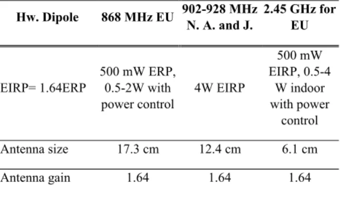
Figure 1. Link budget for a passive RFID system with the same path loss for uplink and downlink [5] Reader EIRP (equivalent isotropically radiated power) or ERP (effective radiated power) given with Pt Gt product are limited by authorities, see table 1.
When we look at equation (1), only parameters we can adjust in the wireless link are Gr tag antenna gain
and L path loss. Gr tag antenna gain is traded with
antenna size, getting bigger with decreasing frequency restricting RFID label size and path loss
increases with frequency. Therefore, for a given size of receive antenna, the environment that RFID tag operated affects your choice of wireless link frequency for maximum power transfer. For operating frequency band, 868 MHz or 915 MHz depending upon countries are employed mostly.
Table 1. Half wavelength dipole antenna sizes and allowed maximum output power for RFID applications
for different frequency bands [9]
Hw. Dipole 868 MHz EU 902-928 MHz N. A. and J. 2.45 GHz for EU
EIRP= 1.64ERP 500 mW ERP, 0.5-2W with power control 4W EIRP 500 mW EIRP, 0.5-4 W indoor with power control Antenna size 17.3 cm 12.4 cm 6.1 cm Antenna gain 1.64 1.64 1.64
Power obtained on RFID antenna must be utilized effectively in circuits because very low amount of power reaches RFID tag in obstructed and noisy environment. Induced voltage on an antenna is rectified or multiplied to supply the power to demodulator, backscatter modulator and digital part with peripherals on passive RFID, see figure 2. Voltage multiplier or rectifier power conversation efficiency (PCE) η also put constraints on the range because substrate couplings, parasitics, threshold voltage drop and reverse leakage current of diodes reduces efficiency. Self-synchronous and differential rectifier is proposed to effectively remove these effects at critical communication distance [10], [11] and [12], see figure 3. The best result is achieved in [11] with %66 PCE.
Figure 2. Passive RFID with subcircuits and monostatic and bistatic zero-IF reader
In subsequent stages of rectifier or multiplier, RFID digital core dissipates the most amount of power at one time restricting tag distance because activity of
demodulator, backscatter modulator and standard functionalities on digital core are distributed over time. By using ultra low power design techniques, a RFID processor at 0.33 V supply voltage and 1 MHz input clock with 80 nW power consumption has been designed [13].
In addition to that, when the induced power changes on the RFID antenna, non-linear effects manifest themselves and change RFID input impedance. Therefore, to have long communication distance, RFID input impedance must be matched to antenna impedance at critical communication distance in which RFID just obtains the power to run [10], called threshold.
Using the latest results in the literature %66 PCE and 80nW RFID processor Ptag, equal to 242.5 nW
incident power on the antenna, for the range equation given in (4) for free space, it is found that range is less than or equal to 64.8 m at 868 MHz for half wavelength dipole tag antenna of gain 1.64 and 500 mW ERP in perfect matching conditions assumed. If power is increased to 2W ERP, distance becomes 129.7 m.
𝑑
(4)
On the other hand, downlink communication is restricted by the backscattered power in either one state during reflection. When it is assumed that in perfect matching condition half of incident power is reflected in ASK backscatter modulation, 121.3 nW power are reflected during high impedance states. -102 dBm power is obtained on reader antenna for half wavelength dipole antenna with 1.64 gain (Gt reader
receive antenna gain), using equation (5). If power is increased to 2W ERP, -108.5 dBm power is obtained on reader PRX.
𝑃 𝑃
(5)
-108.5 dBm signal is around the thermal noise level and falls below reader threshold for monostatic configuration around -80 dBm. Therefore, bi-static configuration, separate TX and RX antenna, with high antenna gain, narrow band filter and low noise feature must be employed to overcome noise floor limitation (SNR) [4], shown in figure2. For the amount of power more than 2W ERP, distant tag can
Kazım Evecan
Passive RFID Uplink and Downlink Link Budget and Comparison of ASK and BPSK Backscatter Modulations
be energized but downlink signal would be masked by thermal noise in this case. The same result for PRX
signal level can be found by log distance path loss model with reduced distance.
3. REFLECTION COEFFICIENT AND POWER EQUATIONS ON AN RFID
FRONT-END MODEL
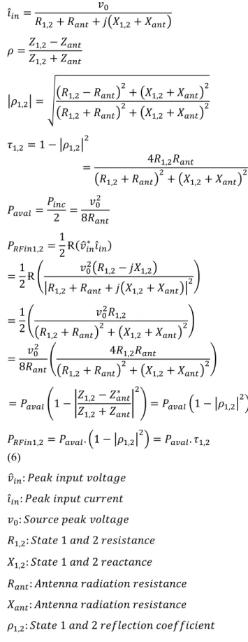
In figure 3, passive RFID front-end model is shown and power induced on antenna, antenna impedance and RFID chip input impedance are represented by a power source with V0 open circuit voltage, Zant and
Zload respectively. RFID input impedance is
capacitive due to parasitic capacitances of transistors in rectifier circuit set by semiconductor technology in use and When the induced power changes on the RFID antenna, non-linear effects manifest themselves changing RFID input impedance. That is why a matched inductive antenna to RFID input impedance is employed at tag threshold. 1 and 2 indices for Zload
is used to show different states of input impedance during backscatter modulation.
Figure 3. Passive RFID antenna model, rectifier and load @868 MHz 𝑍 𝑅 𝑗𝑋 ; 𝑍 𝑅 , 𝑗𝑋, 𝑣 𝑣 𝑅 , 𝑗𝑋, 𝑅 , 𝑅 𝑗 𝑋 , 𝑋 𝚤̂ 𝑣 𝑅 , 𝑅 𝑗 𝑋 , 𝑋 𝜌 𝑍 , 𝑍 𝑍 , 𝑍 𝜌 , 𝑅 , 𝑅 𝑋 , 𝑋 𝑅 , 𝑅 𝑋 , 𝑋 𝜏 , 1 𝜌 , 4𝑅 , 𝑅 𝑅 , 𝑅 𝑋 , 𝑋 𝑃 𝑃 2 𝑣 8𝑅 𝑃 , 1 2Ɍ 𝑣∗ 𝚤̂ 1 2Ɍ 𝑣 𝑅 , 𝑗𝑋 , 𝑅 , 𝑅 𝑗 𝑋 , 𝑋 1 2 𝑣 𝑅 , 𝑅 , 𝑅 𝑋 , 𝑋 𝑣 8𝑅 4𝑅, 𝑅 𝑅 , 𝑅 𝑋, 𝑋 𝑃 1 𝑍 , 𝑍∗ 𝑍 , 𝑍 𝑃 1 𝜌 , 𝑃 , 𝑃 . 1 𝜌 , 𝑃 . 𝜏 , (6) 𝑣 : 𝑃𝑒𝑎𝑘 𝑖𝑛𝑝𝑢𝑡 𝑣𝑜𝑙𝑡𝑎𝑔𝑒 𝚤̂ : 𝑃𝑒𝑎𝑘 𝑖𝑛𝑝𝑢𝑡 𝑐𝑢𝑟𝑟𝑒𝑛𝑡 𝑣 : 𝑆𝑜𝑢𝑟𝑐𝑒 𝑝𝑒𝑎𝑘 𝑣𝑜𝑙𝑡𝑎𝑔𝑒 𝑅 , : 𝑆𝑡𝑎𝑡𝑒 1 𝑎𝑛𝑑 2 𝑟𝑒𝑠𝑖𝑠𝑡𝑎𝑛𝑐𝑒 𝑋 , : 𝑆𝑡𝑎𝑡𝑒 1 𝑎𝑛𝑑 2 𝑟𝑒𝑎𝑐𝑡𝑎𝑛𝑐𝑒 𝑅 : 𝐴𝑛𝑡𝑒𝑛𝑛𝑎 𝑟𝑎𝑑𝑖𝑎𝑡𝑖𝑜𝑛 𝑟𝑒𝑠𝑖𝑠𝑡𝑎𝑛𝑐𝑒 𝑋 : 𝐴𝑛𝑡𝑒𝑛𝑛𝑎 𝑟𝑎𝑑𝑖𝑎𝑡𝑖𝑜𝑛 𝑟𝑒𝑠𝑖𝑠𝑡𝑎𝑛𝑐𝑒 𝜌 , : 𝑆𝑡𝑎𝑡𝑒 1 𝑎𝑛𝑑 2 𝑟𝑒𝑓𝑙𝑒𝑐𝑡𝑖𝑜𝑛 𝑐𝑜𝑒𝑓𝑓𝑖𝑐𝑖𝑒𝑛𝑡 𝜏 , : 𝑆𝑡𝑎𝑡𝑒 1 𝑎𝑛𝑑 2 𝑡𝑟𝑎𝑛𝑠𝑚𝑖𝑠𝑠𝑖𝑜𝑛 𝑐𝑜𝑒𝑓𝑓𝑖𝑐𝑖𝑒𝑛𝑡 𝑃 : 𝐼𝑛𝑐𝑖𝑑𝑒𝑛𝑡 𝑝𝑜𝑤𝑒𝑟 𝑃 , : 𝑆𝑡𝑎𝑡𝑒 1 𝑎𝑛𝑑 2 𝑡𝑟𝑎𝑛𝑠𝑚𝑖𝑡𝑡𝑒𝑑 𝑝𝑜𝑤𝑒𝑟 𝑡𝑜 𝑅𝐹𝐼𝐷 𝑃 𝜌 , : 𝑅𝑒𝑓𝑙𝑒𝑐𝑡𝑒𝑑 𝑝𝑜𝑤𝑒𝑟
Transmitted power to RFID from incoming RF field before backscatter modulation is given in (5) [7]. As we remember from transmission line theory, impedance matching, equal to zero reflection coefficient, is required to achieve maximum power transfer. In our case, conjugate match load (Zant =
Z*load) corresponds to zero reflection coefficient and
half of the power induced on antenna is transferred to load (Pinc/2).
4. BACKSCATTER MODULATION POWER EQUATIONS
There are two common backscatter modulations ASK and BPSK to be considered. On the reader side, average difference power radiated from antenna resistance between two states given in (8) is considered for data and the absolute power given in (7) must be above reader threshold at least one of two state. During backscatter communication in state 1 and 2, power transmitted to or obtained by tag is given in (9). (8) restricts communication range.
𝑃 |𝑝 𝑖 𝑝 𝑖 | 2 𝑅 𝑖 , 𝑣 𝑍 𝑍 , 𝑣 2𝑅 1 𝜌 , 𝑃 , Ɍ 𝑣∗ 𝚤̂ , , 𝑃 , , (7) 𝑃 𝑃 |𝑝 1 𝜌 𝑝 1 𝜌 | (8) 𝑃 𝑃 𝑝 1 |𝜌 | 𝑝 1 |𝜌 | (9) 𝑃 , : 𝑆𝑡𝑎𝑡𝑒 1 𝑎𝑛𝑑 2 𝑑𝑖𝑠𝑠𝑖𝑝𝑎𝑡𝑒𝑑 𝑝𝑜𝑤𝑒𝑟 𝑜𝑛 𝑎𝑛𝑡𝑒𝑛𝑛𝑎 𝑃 : 𝐴𝑣𝑒𝑟𝑎𝑔𝑒 𝑑𝑖𝑠𝑠𝑖𝑝𝑎𝑡𝑒𝑑 𝑝𝑜𝑤𝑒𝑟 𝑜𝑛 𝑎𝑛𝑡𝑒𝑛𝑛𝑎 𝑏𝑒𝑡𝑤𝑒𝑒𝑛 𝑠𝑡𝑎𝑡𝑒 1 𝑎𝑛𝑑 2 𝑃 : 𝐴𝑣𝑒𝑟𝑎𝑔𝑒 𝑖𝑛𝑝𝑢𝑡 𝑝𝑜𝑤𝑒𝑟 𝑝 , : 𝐷𝑢𝑡𝑦 𝑐𝑦𝑐𝑙𝑒 𝑓𝑜𝑟 𝑠𝑡𝑎𝑡𝑒 1 𝑎𝑛𝑑 2, 0 𝑝 , 1 𝑎𝑛𝑑 𝑝 𝑝 1
Matched load, open circuit and short circuit for ASK backscatter is easily grasped on the model in figure 3. For BPSK backscatter, real part of reflection coefficient is zero and imaginary part equal in amount but opposite in sign, ±m. Modulation is achieved by changing RFID input capacitance equal amount and
so changing phase of voltage signal on antenna radiation resistance in equal degree. Base band signal from tag to reader is proportional to this phase signal φ which must be detectable on the reader side. Resistance and reactance values of RFID input impedance for BPSK equal amount of mismatched condition are found below.
𝜌 , 𝑗𝑚 0 𝑚 1 (10) 𝜑 , tan 𝑚 𝑉𝑜𝑙𝑡𝑎𝑔𝑒 𝑝ℎ𝑎𝑠𝑒 𝑜𝑣𝑒𝑟 𝑅 (11) 𝑍 , 𝑍 , 𝑗𝑋 , , 𝑅 (12) 𝑋 , 𝑋 (13) 𝑅 , 𝑅 (14)
In table 2, induced RFID chip and backscatter power equations for different modulations are presented. RFID-A and RFID-B can be run from longer distance than RFID-C increasing duty cycle up to 0.9 or 0.95 because RFID input power and average difference backscatter power have increasing trends in ASK backscatter in contrast to conflicting trends in BPSK modulation. OC case in RFID-A brings more average difference backscatter power on the reader side than SC case in RFID-B, as shown in [1]. However, in standards such as EPC Class1 Gen2 (GS1), each symbol has equal amount of time for high or low state, forcing %50 duty cycle and state duration for ASK and BPSK backscatter modulation types. In practice it is hard to create OC case. Actually, there is always reflection due to finite mismatches.
Kazım Evecan
Passive RFID Uplink and Downlink Link Budget and Comparison of ASK and BPSK Backscatter Modulations
Table 2. Backscatter modulation comparisons [6]
RFID-A RFID-B RFID-C Type of Modulation ASK backscatte r ASK backscatter BPSK backscatter State 1 𝜌 0 𝑝 𝐷𝐶 Matched load 𝜌 0 𝑝 𝐷𝐶 Matched load 𝜌 𝑗𝑚 𝑝 0.5 Equal mismatch State 2 𝜌 1 𝑝 1 𝐷𝐶 Open circuit (OC) 𝜌 1 𝑝 1 𝐷𝐶 Short circuit (SC) 𝜌 𝑗𝑚 𝑝 0.5 Equal mismatch Average difference backscatter power 𝑃 𝐷𝐶 𝑃 𝑃 3𝐷𝐶 2 𝑃 𝑃 𝑚 𝑃 Average input power 𝑃 𝐷𝐶𝑃 𝑃 𝐷𝐶𝑃 𝑃 1 𝑚 𝑃 State 1 backscatter power 𝑃 𝑃 𝑃 𝑃 1 𝑚 State 2 backscatter power 0 𝑃 𝑃 4𝑅 𝑅 𝑋 𝑃 , 𝑃 1 𝑚
5. REALIABILITY OF BPSK AND ASK MODULATIONS AND MINIMUM SNR
Minimum signal to noise ratio for a targeted BER is required to be known for reader sensitivity. Signal from tag to reader passes through multipath environment getting attenuated by reflected signals from near-by objects, called multipath fading for small amplitudes and shadowing for large amplitudes. In addition to that, channel noise must be considered to see effects of real environment challenges. On signal side, backscattered difference power is relevant for reader, given in equation (8). To see effect of scattered signals and noise on the signal power, proper channel models are employed depending upon application environment. Weak ASK and BPSK backscatter modulated signals are assumed to pass through AWGN channel (Additive White Gaussian Noise), Rayleigh fading channel, useful model when there is no line of sight or there are many reflectors, and Rician fading channels to see their performances, used when the line of sight component
is much stronger than others figure 4. Bit error probability is given in (15), (16) and (17) for AWGN, Rayleigh and Rician channel models, Eb energy per
bit and N0 noise. When you think about situation that
the same place located tags with BPSK modulation index 0.5, 0.41 change in reactance is equal to resistance, 0.32 and ASK %50 duty cycle has -3 dB, -4.7 dB, -7 dB and -3 dB lower SNR ratio with respect to a tag BPSK modulation index 0.707 figure 4. They are compared to exhibit SNR and BER performances considering differences by simulations in theory and
10 million normal distributed samples in figure 4
[14]. k is ratio of dominant LOS component power to scattered components power in Rician channel model.
𝑃 𝑒𝑟𝑓𝑐 (15) 𝑃 1 (16) 𝑃 𝑒𝑟𝑓𝑐 (17)
Figure 4. ASK and BPSK backscatter modulation BER curve for AWGN, Rayleigh and Rician channel models BER value for BPSK m=0.707 tag is always lower than other ASK and BPSK tags and %50 ASK and BPSK m=0.5 are the same although input power to tag in BPSK tag is %50 higher than ASK tag. Effect of noise for low modulation indexes is higher since
signal power is low. There is always needed much higher signal to noise ratio in multiple reflector environment.
Practical value of 10-4 and 10-5 BER are used general.
For example, 10-4 and 10-5 BER result in 0.05 and
0.005 read error rate for 64 byte EPC (Electronic Product Code) and similarly, 0.01 and 0.001 for 12 byte EPC. For 10-5 BER value, minimum SNR levels
are around 9.5 dB, 11 dB and 44 dB corresponding to AWGN, Rician for k=25 and Rayleigh fading channels.
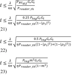
6. MAXIMUM RANGE
During backscatter modulation, tag can be run out of energy due to low state of symbol. For ASK case, there are two situations limiting the uplink distance. First, it is considered that tag has enough energy on the capacitor Cload during low level of symbol with
short duration for fast enough communiation not to run out of energy as in sensor tags, see figure 3. In this case, we are limited with equation (18). On the other hand, equation (19) limits uplink distance for tags with small Cload and low state of symbol with
long duration for low speed communications. For BPSK case, equation (4) can be rewritten as in (20). Equations are given for %50 state durations.
𝑟 , (18) 𝑟 | | | | (19) 𝑟 (20)
For downlink communication, working distance can be rewritten for ASK and BPSK modulations in similar case to above (21), (22) and (23) assuming that tag obtains only enough power to run, Gt reader
receive antenna gain. For ASK and BPSK modulations, backscatter difference power and so PBS1,2 for either one of states must be above reader
receive threshold, Preader_th represents this level.
Reader sensitivity can be found by Preader_th=-174
dBm/Hz+NF+10log(BW)+SNRmin, NF noise figure
of system, BW bandwidth and SNRmin minimum
signal to noise ratio of the system, sum of channel
SNR, RF chain SNR and analog baseband SNR. First three terms represents integrated noise of system called noise floor.
𝑑 _ 𝑑 . _ | | (21) 𝑑 . _ | | | | (22) 𝑑 _ (23)
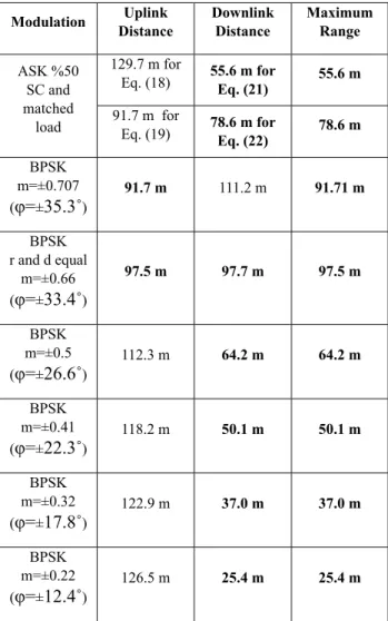
As stated before maximum communication distance is restricted by either uplink or downlink communication, found by min(r,d) for two modulations. Using the latest results in the literature %66 PCE η, 80nW RFID processor Ptag, half
wavelength dipole tag antenna gain 1.64 for given size, reader receive antenna gain 6.56 (8.14 dB), 2 W ERP, 0 state 1 reflection coefficient ρ1, -1 state 2
reflection coefficient ρ2 and -101 dBm reader
threshold Preader_th with GS1 640 kHz, 5.5 dB noise
figure and 9.5 dB more than thermal noise at 868 MHz in perfect matching conditions assumed, results are listed in table 3.
Kazım Evecan
Passive RFID Uplink and Downlink Link Budget and Comparison of ASK and BPSK Backscatter Modulations
Figure 5. Uplink distance for ASK and BPSK modulations for given parameters
Figure 6. Downlink distance for ASK and BPSK Modulation for given parameters
During design time, rectifier efficiency η, tag power dissipation Ptag, tag antenna gain Gr for a given RFID tag
label size, reader threshold Preader_th and transmit power
PERP limited by authoroties are known and for given parameters above, only, reader receive antenna gain Gt and m modulation index for ASK and BPSK modulations can be changed. This point can be utilized to find antenna gain Gt and m modulation index to make d equal to r, given in (24), (25) and (26). If system is uplink limited, the distance difference brings more signal power on reader side so more SNR and reliable operation. When downlink limits distance, equations (24), (25) and (26) must be considered. We face this situation now and in further improvement of Ptag and η and higher Preader_th requirement. The same results can be found by log distance path loss model.
𝐺 . _ , (24) 𝐺 _ | | | | (25) 𝐴 𝑃 _ 𝑃 𝜂 𝐵 2𝑃 𝐺 𝑚 √ (26)
Table 3. Maximum free space range for η=0.66, Ptag=80nW, Gr=1.64, Gt=6.56, Preader_th=-101 dBm,
PERP=2W @868MHz
Modulat on D stance Upl nk Downl nk D stance Max mum Range
ASK %50 SC and matched
load
129.7 m for
Eq. (18) 55.6 m for Eq. (21) 55.6 m 91.7 m for
Eq. (19) 78.6 m for Eq. (22) 78.6 m BPSK m=±0.707 (φ=±35.3˚) 91.7 m 111.2 m 91.71 m BPSK r and d equal m=±0.66 (φ=±33.4˚) 97.5 m 97.7 m 97.5 m BPSK m=±0.5 (φ=±26.6˚) 112.3 m 64.2 m 64.2 m BPSK m=±0.41 (φ=±22.3˚) 118.2 m 50.1 m 50.1 m BPSK m=±0.32 (φ=±17.8˚) 122.9 m 37.0 m 37.0 m BPSK m=±0.22 (φ=±12.4˚) 126.5 m 25.4 m 25.4 m
After RFID tag design, changes can be made on Gt
reader receive antenna gain and reader threshold Preader_th (actually there is no change) to make two distances equal. If modulation index m is bigger than m=0.66, tag is limited by uplink distance. Modulation index value close to 1 cannot be used because tag cannot be energized (20). Low gain Gt antenna can be
used for cost reduction or Preader_th reader threshold requirement can be relaxed to higher values with low BER values while keeping the modulation index and so uplink distance the same (23). Actually, uplink limited system has more reliable operation. In ASK case, there is similar situation. On the other hand,
below m=0.66 value, signal will not be fetched for the distances more than maximum downlink distance. Higher gain receive antenna can bring additional degree of freedom to increase downlink distance as much as possible or similarly Preader_th reader threshold level can be reduced for this purpose at the cost of more BER while keeping the modulation index m and so uplink distance the same. However, it is needed to be considered that baseband signals with low modulation index m is hard to detect on reader side and effect of noise inceases. That is why for the environment being operated the lowest level modulation index m must be decided first. Then, antenna gain Gt and Preader_th can be adjusted to make two distances equal, a kind of trade-off (20) and (23). Further reduction of Ptag and improvement of η has
also bright future in terms of increasing distance, modulation index m and so increasing SNR on reader (23). In ASK case, situations are similar. In addition, if downlink limited distance, antenna gain could be increased to 35.7 (15.5 dBi) and 8.8 (9.5 dBi) to make two distances equal (24) and (25).
7. RESULTS
In this study, uplink and downlink distances are shown for UHF RFID in detail and parameters to make two distance equal are given. Also, it is shown that reflected signal levels require separate TX and RX antenna, bistatic configuration. Latest works show that BPSK tags are proper choice for working distance and reliability.
Complete link budget in a RFID system is given for different environments. Power consuming parts effecting this range in a passive RFID hardware are presented with power reduction techniques to have longer range because distant operation is desired in harsh and noisy working environments. It is shown on the range equations by using the results from literature that both uplink and downlink communication distance must be considered during the design. Hence, in the future we will see next generation RFID tags and readers working from longer range in challenging environments due to low power nature of RFID tags, especially in supply chain management and mid-range passive wireless sensor network (WSN) environment and lower detection threshold of readers.
Parasitics included simulations in TSMC 0.18 um RF technology show that differential rectifier efficiency
in figure 3 is around %66-68 over wide range of input power up to more than -37 dBm with fine tunings. Latest works on RFID tag processor achieved 80 nW in similar technology node [13]. With these points and reasonable parameters given in table 3, two state difference electromagnetic power reaching RFID reader is around integrated or thermal noise of systems. This result directs to separate TX and RX antenna bistatic configuration for RFID reader. ASK tag with large capacitor at the rectifier output and matched load have longer uplink distance than other ASK tags and BPSK tags when you look at equations (18), (19), (20) and table 3. On the other hand, Downlink limits due to noise floor of reader. For this purpose, high gain reader receive antenna must be employed to increase range considering cost containment. Similarly, higher modulation index BPSK modulation has higher downlink distance. In the presence of current improvements, BPSK tags are proper choice in noisy environments and have higher working distance. High modulation index BPSK modulation has more reliable operation with low BER proper to use harsh environments for safe information and to decrease error. None the less, situation reverse to ASK in terms of working distance and reliability if high antenna gain Gt around 16 dBi
is used. The same results and conclusions can be found by log distance path loss model except running distance.
Simulations on different communication channel models show that noise requires wide range of modulation index tags depending upon operating environment. One tag with programmable mismatch in BPSK case like capacitor banks looks more logical. Some other opportunities are seen. First, when you look at equation (8) and (9), there is a potential to use available power in BPSK modulation for higher speed and bandwidth efficient M-ary modulation formats such as QAM. In table 3, the same situation is seen by looking at decreasing angle arctan(±m) and decreasing magnitude (or distance) (1+m2)P
aval going
down to table. Realization can be done employing more number of varactors on BPSK modulator over positive x-plane at cost of the distance penalization. Advantage of M-ary modulation formats is reduction of the amount of processing time on massive deployments. Second, for portable devices, operation distance is defined and less than maximum distance, low cost reader hardware with small power amplifier
Kazım Evecan
Passive RFID Uplink and Downlink Link Budget and Comparison of ASK and BPSK Backscatter Modulations
and fast operation can be used to dissipate less energy, to have long battery duration, to have less air traffic and to create less electromagnetic interference.
REFERENCES
[1] P. Nikitin and K. V. . Rao, “Theory and measurement of backscattering from RFID tags,” IEEE Antennas Propag. Mag., vol. 48, no. 6, pp. 212–218, Dec. 2006.
[2] S. S. Srikant and R. P. Mahapatra, “Read Range of UHF Passive RFID,” Int. J. Comput. Theory Eng., vol. 2, no. 3, pp. 323--325, 2010. [3] Y. Gao, Z. Zhang, H. Lu, and H. Wang, “Analysis and calculation of read distance in passive backscatter RFID systems,” LISS 2012 - Proc. 2nd Int. Conf. Logist. Informatics Serv. Sci., vol. 2, no. 1, pp. 905–912, 2013. [4] J. D. Griffin and G. D. Durgin, “Complete
Link Budgets for Backscatter-Radio and RFID Systems,” IEEE Antennas Propag. Mag., vol. 51, no. 2, pp. 11–25, Apr. 2009. [5] P. Nikitin, K. V. S. Rao, S. Lam, and W. Ave,
“UHF RFID TAG CHARACTERIZATION : OVERVIEW AND STATE-OF-THE-ART,” no. 2, pp. 2–7.
[6] F. a. Hussien, D. Z. Turker, R. Srinivasan, M. S. Mobarak, F. P. Cortes, and E. Sanchez-Sinencio, “<title>Design considerations and tradeoffs for passive RFID tags</title>,” vol. 5837, pp. 559–570, Jun. 2005.
[7] U. Karthaus and M. Fischer, “Fully Integrated Passive UHF RFID Transponder IC With 16 . 7- W Minimum RF Input Power,” vol. 38, no. 10, pp. 1602–1608, 2003.
[8] M. Viswanathan and S. Edition,
“SIMULATION OF DIGITAL
COMMUNICATION SYSTEMS USING MATLAB.”
[9] P. Note, “ERC Recommendation 70-03,” no. February, 2014.
[10] M. H. Ouda et al., “for Implantable Intraocular Pressure Monitoring,” pp. 1–8. [11] K. Kotani, A. Sasaki, T. Ito, and S. Member,
“High-Efficiency Differential-Drive CMOS Rectifier,” vol. 44, no. 11, pp. 3011–3018, 2009.
[12] R. Vaddi, R. P. Agarwal, S. Dasgupta, and T. T. Kim, “Design and Analysis of Double-Gate MOSFETs for Ultra-Low Power Radio Frequency Identification (RFID): Device and Circuit Co-Design,” J. Low Power Electron. Appl., vol. 1, no. 3, pp. 277–302, Jul. 2011. [13] W. Shi, C. S. Choy, J. Guo, C. F. Chan, K. N.
Leung, and K. P. Pun, “A 90nm RFID tag’s baseband processor with novel PIE decoder and uplink clock generator,” Midwest Symp. Circuits Syst., pp. 644–647, 2010.
[14] DSPLOG, “Communication Channels.” [Online]. Available: http://www.dsplog.com.
![Figure 1. Link budget for a passive RFID system with the same path loss for uplink and downlink [5] Reader EIRP (equivalent isotropically radiated power) or ERP (effective radiated power) given with P t G t product are limited by authorities, see](https://thumb-eu.123doks.com/thumbv2/9libnet/4371090.73541/3.892.470.832.156.931/figure-downlink-equivalent-isotropically-radiated-effective-radiated-authorities.webp)
![Table 2. Backscatter modulation comparisons [6]](https://thumb-eu.123doks.com/thumbv2/9libnet/4371090.73541/7.892.83.438.130.682/table-backscatter-modulation-comparisons.webp)