Contents list available at IJRED website
Int. Journal of Renewable Energy Development (IJRED)
Journal homepage: http://ejournal.undip.ac.id/index.php/ijred
On The Eddy Current Losses in Metallic Towers
Ibrahim Mahariq
a*, Svetlana Beryozkina
a, Huda Mohammed
b,and Hamza Kurt
c
aCollege of Engineering and Technology, American University of the Middle East, Kuwait
bDepartment of Electrical and Electronics Engineering, University of Turkish Aeronautical Association, Turkey cElectrical & Electronics Engineering, Faculty of Engineering, TOBB University of Economics and Technology, Turkey
ABSTRACT. The existence of magnetic field around high-voltage overhead transmission lines or low-voltage distribution lines is a known
fact and well-studied in the literature. However, the interaction of this magnetic field either with transmission or distribution towers has not been investigated. Noteworthy it is to remember that this field is time-varying with a frequency of 50 Hz or 60 Hz depending on the country. In this paper, we studied for the first time the eddy currents in towers which are made of metals. As the geometrical structures of towers are extremely complex to model, we provide a simple approach based on principles of electromagnetism in order to verify the existence of power loss in the form of eddy currents. The frequency-domain finite difference method is adapted in the current study for simulating the proposed model. The importance of such a study is the addition of a new type of power loss to the power network due to the fact that some towers are made of relatively conductive materials. ©2020. CBIORE-IJRED. All rights reserved
Keywords: Eddy current, finite difference method, metallic towers, power systems
Article History: Received: Oct 16, 2019; Revised: December 10, 2019; Accepted: January 9, 2020; Available online: February 15, 2020
How to Cite This Article: Mahariq, I., Beryozkina, S., Mohammed, H., Kurt, H.(2020), On the eddy current losses in metallic towers.
International Journal of Renewable Energy Development, 9(1), 1-6. https://doi.org/10.14710/ijred.9.1.1-6
1. Introduction
It is a well-known fact that some of electrical energy generated and supplied to a distribution utility does not reach to the end consumer. Power generated in power stations passes through large and complex networks like transformers, overhead lines, cables and other equipment, which cause energy losses in the system. Losses in the transmission and distribution system are defined as technical and non-technical losses (Gustafson et al. 1989, Davidson et al. 2002). Some of the energy is lost as heat in the conductors, some are absorbed in insulating materials, and some of energy is dissipated into a magnetic field. So, different types of losses are present regardless of how carefully the system is modeled and designed.
Focusing on the magnetic losses, some literatures were dedicated to focus on the magnetic and electric fields around the overhead transmission lines (Grigsby 2007, Pettersson 1996, Ippolito et al. 2015, Liu et al. 1996, Pathak et al. 2003, Budnik et al. 2006). The environmental effect of the electromagnetic fields emitted from transmission lines on electrical and electronic instruments near it, the probability of affecting its operation and the effect of these fields on human’s health have been one of the important concerns for many researches. Different methods was presented for minimising the magnetic field according to the place of the conductor in space (Pettersson 1996), or using passive
*Corresponding author: [email protected]
circuits for the reduction of the harmful magnetic field for instance but not limited to Ippolito et al. (2015). The magnetic field around the conductors of the transmission lines reduces as the distance from the tower increases (Pathak et al. 2003) that is why high voltage transmission towers should not be located near residential areas as much as possible.
When talking about environment subjects that are affected by the magnetic field of transmission lines, it is worthy to shed light on the tower holding it too. Most of electrical transmission towers in most of countries are made of steel as for its high mechanical strength withstanding under bad climatic conditions. In addition, steel needs less maintenance compared to other material types. These towers are interacting with the magnetic field produced by the current carrying conductors of the three-phase transmission line (Ryan 2001). The transmission tower has a complex design characterized in a way to meet the special needs from structural/mechanical and electrical points of view.
The effect of the magnetic field on the maintenance personnel and how different type of towers have different susceptible to electromagnetic field is discussed in (Zemljaric 2011), where the author illustrates that the geometry of the one-circuit Y shaped tower is less favorable than the barrel two-circuit tower. Also, climbing routes which used for maintenance purposes were analyzed and the electric and magnetic fields are
calculated in the same study. All the electric and magnetic field calculations can be used for any shape of electric structures. The calculations of magnetic fields have been done using different numerical methods. Liu et al. (1996) discussed the environmental effects due to transmission lines using charge simulation method as a means of calculating the magnetic field around the three phase conductors. Budnik et al. (2006) used exact and approximate methods for analyzing magnetic field around the overhead power lines, obtaining magnetic field in the free space from Biot-Savart law, the influence of earth current on the magnetic field above the surface of the earth can be neglected when compared with the currents flowing in the overhead conductors. Hwang (1997) applied finite element method to calculate the forces and eddy current losses induced in the structural steel that always run parallel to the three-phase line which is used to provide mechanical protection for the current lines. As it is not easy to use an analytical method for the eddy currents induced in conducting materials by time varying magnetic field, most of researches dealing with a current carrying problems uses Poisson’s equation for finding the magnetic vector potential with the well-defined source current density (Chari et al. 1977). The same thing was used in Chari (1974) for eddy current problems by determining the current density and obtaining the losses by evaluating it using the volume integral. The formulation of eddy current and interface boundary conditions are described briefly in (Biddlecombe et al. 1982, Rodger et al. 1983). Dein (2014) presented the interaction between the conductors of the transmission lines and the holding tower by studying the effect of the number of infinite line charges per conductor of the overhead lines. In Zhang et al. (2006), the tower and the phase conductors are divided into short segments and solved by the charge simulation method. Meanwhile, the effect of the tower configurations along the insulator was investigated in Zhao et al. (2000). The application of finite difference method is not unique, i.e., other numerical methods such as spectral element method can also be utilized due to its high accuracy (Mahariq et al. 2017, Mahariq 2017),
In this paper we confirm on the existence of eddy-current losses in transmission towers. Although the loss is found to be slight, especially at balanced conditions, eddy current is successfully calculated in the tower. By using the finite difference method for solving Maxwell’s differential equations in low frequency problems, the resulting eddy-currents losses in the tower are estimated at different material properties. Our approach connects the magnetic calculation and the electric calculation by the introduction of Faraday’s law in the electric field calculation. The equation of the magnetic vector potential is determined and solved by the aid of finite deference method. In addition to its mathematical modelling and importance to researchers interested in the field, this study provides important keys to towers manufacturers in selecting the proper materials so that the eddy-current originated losses are minimum. The paper is arranged as follows: Section 2 reviews the derivations of the governing partial differential equations in magnetostatics. In section 3, the spatial discretization of the problem by finite difference method is introduced. Results and discussions are drawn in section 4, and finally, some conclusions and
future works associated with the interest of this paper is introduced in the last section.
2. Formulation of Eddy Currents
High voltage transmission lines operate at low frequency thus the associated formulation can be described as quasi static fields. Inside the conductors the displacement current D is negligible (Biddlecombe et al. 1982) meaning that no currents flow normal to the surface of the conductor. The magnetic field intensity H outside the conductor is excited by the free current density J of sinusoidal excitation at the angular frequency (ω). Amperes-law (considering !"!# ≈ 0), Faradays-law and magnetic flux continuity are the basic set of equations for magnetodynamic (quasi-stationary) field. These laws read respectively as:
H J
Ñ ´
!!" !"
=
, (1)B
E
t
Ñ´ =
-
!!" !!" , (2)0
B
Ñ× =
!!" , (3)where 𝐵 = 𝜇𝐻, 𝐽 = 𝜎𝐸 with 𝜇, 𝜎 being the magnetic permeability and electrical conductivity of the medium, respectively. In order to turn these first-order differential equations into second order equation having one unknown, the magnetic potential field 𝐴 is introduced by 𝐵 = ∇×𝐴. By substitution, the partial differential equation that governs the magnetic field can be expressed as (Sykulski 2012):
2
A
A
J
t
µs
µ
Ñ
-
=
-
!!" !!" !!" . (4)However, since equation (4) is the A-formulation for the quasi stationary magnetic field in the time domain, if !#! = 𝑗𝜔 is considered, the equation can be rewritten in the frequency domain as:
2
A j
wµs
A
µ
J
Ñ
!!"-
!!"= -
!!", (5)where 𝐴 and 𝐽 are the z-direction components of the magnetic vector potential (𝑤𝑏/𝑚) and the excitation source current density (𝐴/𝑚8) respectively, and ∇8 is the
vector Laplacian. The eddy current density induced in a metal due to a magnetic field produced by a current-carrying conductor is:
J
e
=
j
sw
!!"A
!!". (6)
And the two dimensional integral form of the eddy current loss (Hwang 1997) is satisfied by the equation:
*
(
/ )
P
e
= òò
J J
e e
s
dxdy
, (7)where 𝑱𝒆∗ is the conjugate term of the eddy current density,
𝑷𝒆 is the eddy current losses.
3. Finite Difference Discretization
Three-phase transmission lines produce an electromagnetic field that links the metallic tower and hence, since it is time-varying, it induces eddy currents in the tower. Considering that eddy currents flow in
relatively small area that is well defined Rodger et al. (1983), to minimize the number of unknown variables it is better to define the magnetic field by means of the magnetic vector potential in all regions. Therefore, only one variable (the magnetic potential) is required to be computed in the entire computational domain at the expense of second-order partial differential equation. The following basic assumptions are considered in order to solve for the magnetic field:
• The phase currents are to be sinusoidal and balanced.
• Materials have constant magnetic and electric properties and are not affected by temperature of surrounding.
• The field is quasi-stationary field and hence the displacement current is neglected.
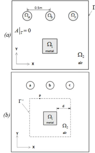
The computational domain is presented in Fig. 1(a) which consists of current-carrying parts and a square metallic piece considered as a part from the tower. Equation (5) can be redefined in each of the mentioned regions as follows: in current-carrying conductors, equation (5) must be satisfied. In the metallic region W1
and the air region W2 the equations are respectively
reduced to
2
A
0
Ñ
!!"=
(8) andÑ
2
A j
-
wµs
A
=
0
!!" !!" (9)Open boundary problems can be solved by picking an arbitrary boundary far enough from the area of interest so that either (𝐴 = 0) for Dirichlet boundary condition, or
ˆn. A
Ñ
for Neumann boundary condition (Mahariq 2017).The distance from the outer boundary to the center of interest should be five times the distance from the outside of the object to the center of interest at least.
The boundary can be defined as homogenous Dirichlet boundary conditions (𝐴== 0) (See Fig. 1(a)) placed at
large distances from the phases in order to ensure accurate solution. However, although this approach is widely used for open boundary problems, it needs extra computational resources. To overcome this issue, we reduced the computational domain to the one shown in Fig. 1(b). That is, the three conductors are excluded from the computational domain and instead the associated resultant magnetic potential is assigned to the new boundary Γ′. The magnetic vector potential at an outer boundary node having the position
r!
due to a phase current Ik can be expressed as:ln , 2 k k I r A az Ap Ak R
µ
p
= - ! = å (10)where 𝑅 denotes the radius of circular conductor carrying the current 𝐼B at the vicinity around the conductor, and 𝐴C
is the resultant magnetic vector potential produced at p due to the three phase conductors.
On the interface between air and the metal, the continuity condition for magnetic field intensity is applied as the interface condition, i.e., (𝐻#)FG= (𝐻#)HI, where 𝐻# is
the tangential component of the magnetic field intensity (Biddlecombe et al. 1982). For simplification purposes, a square region representing a piece from the tower is considered and the power loss to be computed inside it. In fact, the same equations and analysis would be applied if
the whole tower is considered, however this exceeds the limit of our available computational resources.
This problem is a two-dimensional one involving Poisson equation with the consideration that the current density is uniform. Using five-point stencil finite difference method (FDM), one can solve the governing partial differential equations as follows (Causon et al. 2010):
Fig. 1 (a) The geometry of the problem, (b) Reduced
computational domain
2
(
) 2. ( )
(
)
2
( )
2
u
u x
x
u x
u x
x
x
x
@
+ D -
+
- D
D
(11)Applying these approximations on equations (9) and (10) for W1 and W2, we obtain the system of algebraic equations
of the form:
2
4
0
( 1, ) ( 1, ) ( , 1) ( , 1)
( , )
( , )
u
i j
+
+
u
i j
-
+
u
i j
+
+
u
i j
-
-
u
i j
-
h u
b
i j
=
(12)where 𝒊 = 𝟏, 𝟐, … , 𝒏, 𝒖 = 𝒖𝟏, … , 𝒖𝒏 is magnetic vector
potential and 𝜷 = 𝒋𝝎𝝈𝝁.
4. Results and Discussions
Different segment of the tower was considered for the computation of eddy current losses at different places including different metal properties. The calculations start from Maxwell’s equations for the quasi-static magnetic field case. The induced eddy currents depend on dimensions and property of the sample piece of the tower, the distance to the source, and the excitation current.
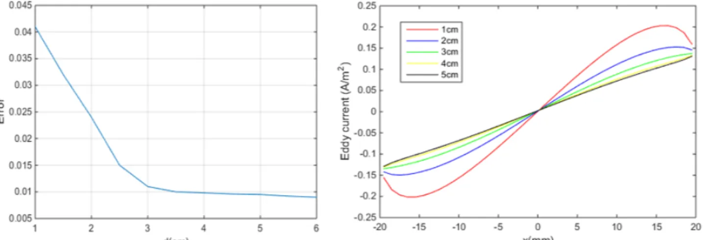
In order to ensure that the application of the Dirichlet boundary condition is enforced at a distance d shown in Fig. 1(b) in such a way that it does not affect the results,
we considered several values of d and see where the convergence occurs. The error is defined as the difference between two consecutive results evaluated from changing the value of d as shown in Fig. 2(a). That is, enforcement of Dirichlet condition at d=3 cm or greater does not have effect on the solution. Fig. 2(b) shows the influence of the chosen distance (d) on the calculated eddy currents at the upper side nodes of the metallic square. The figure shows that the obtained eddy current densities at d less than 3 cm are different than that obtained when d is more than 3 cm (green, yellow, and black in Fig. 2(b)).
For the numerical experiments, Fig. 3 presents the shape of the magnetic vector potential in a 4𝑐𝑚×4𝑐𝑚 metallic square segment of the tower with 𝜇 = 200𝜇X, and 𝜎 = 200𝑆/𝑚 placed at 1 𝑚 below the middle
phase whose current is assumed to be 500A. The associated eddy currents in the considered part of the metallic tower where the computed eddy current losses is
𝑃_= 35 𝑚𝑊. As the induced eddy current depends on the
permeability and conductivity of the transmission tower, at first we calculated the losses in a 4×4 metal with property of (𝜇 =104𝜇X, 𝜎 =5x10⁶S/m) that was used in
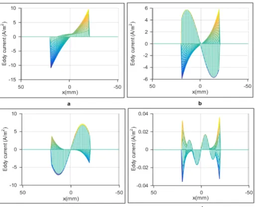
Zemljaric (2011), and the estimated eddy current loss is 40 W. However, both high magnetic and electrical property is not required for the transmission tower, thus less permeability and conductivity is tested in order to find out the effect of these properties on the losses. Fig. 4 illustrates the influence of metals permeability on the induced eddy current in a (4 𝑐𝑚×4 𝑐𝑚) tower slice. Fig. 4(a) shows the eddy current for a metal slice (with 𝜇 = 30𝜇X, 𝜎 =5x10⁴S/m) and the associated eddy current
losses is 2.2 𝑊, and at 𝜇 = 20𝜇X as in Fig. 4(b) the loss
reduces to 0.23 𝑊, and it is 0.16 W , 0.006 W at 𝜇 = 15𝜇X,
𝜇 = 5𝜇X; respectively as shown in 10(c) and 10(d).
Fig. 2 (a) The impact of d on the calculation of the eddy current, (b) The influence of d on the eddy currents in the upper side nodes of
the metallic square.
In order to see the effect of the conductivity we fixed the permeability at (5𝜇°) and tested different conductivity
to show the effect of using a metal with less conductivity at 𝜎 = 5×10e, 10×10f, 5×10f and 10×10g 𝑆/𝑚, the
associated eddy current losses are respectively 32× 10h8 𝑊, 64×10hg 𝑊, 32×10hg 𝑊, 64×10hf 𝑊 that shows a
linear relationship.
The eddy current is also affected by the distance from the source because the magnetic field is getting weaker when moving away from the source so as the distance from the excitation current increases the eddy current decreases and hence eddy current losses decreases. For a 4𝑐𝑚×4𝑐𝑚 metallic segment of the tower with (𝜇 = 5𝜇X, 𝜎 =
10f𝑆/𝑚 , 𝐼 = 500𝐴), the eddy current for a metal segment
placed at a distance of 0.5 m, 1.5 m, 2 m and 2.5 m from power lines, and the resultant eddy current losses decreases from 44×10hf 𝑊 to 17×10hf 𝑊, respectively. To
see the variance clearly we made the same simulation with changing the permeability and conductivity and set to (𝜇 = 200𝜇X, 𝜎 = 200𝑆/𝑚) as presented in Fig. 5.
Making a quick estimation to a steel pole of 8 m height (with 𝜇 = 5𝜇X, 𝜎 = 10000𝑆/𝑚, 𝐼 = 500𝐴) the average eddy
current losses is calculated to be around 4 𝑚𝑊. As a further discussion for the types of materials, the reader may refer to Ref. (Calata et al. 2014, Varga 2014).
Fig. 4 The influence of metals permeability on the induced eddy current: a- The eddy current for metal with property of (µ = 30µX). b- The
eddy current for metal with property of (µ = 20µX). c- The eddy current for metal with property of (µ = 15µX), d- The eddy current for metal
with property of (µ = 5µX).
Fig. 5 Eddy current at different distance from the source with (𝜇 = 200𝜇X, 𝜎 = 200𝑆/𝑚 , 𝐼 = 500𝐴): a) 0.5m. b) 1.5m c) 2m. d) 2.5m.
5. Conclusion
In this paper we presented a method for analyzing the eddy current in transmission towers that it can be applied
to any type of towers by segmenting the tower to small parts for the facilitation of the numerical calculation, and hence saving memory and time. This assembly parts of the tower used as a reference for the entire geometry of the
tower in the calculation of magnetic field and eddy current.
As the magnetic field associated with 50 Hz or 60 Hz, electrical transmission line links the steel tower and induces eddy currents, this eddy current may produce significant losses in the tower depending on the electrical permittivity, magnetic permeability and the carrying current although loss is small at balance condition. Finally and more importantly, this paper provides a deep insight for manufacturer of towers to generated eddy currents based on the electrical conductivity and magnetic permeability of the tower’s material in order to minimize the associated losses.
References
Biddlecombe, C. S., Heighway, E. A., Simkin, J., & Trowbridge, C. W. (1982). Methods for Eddy Current Computation in Three Dimensions. IEEE T Magn, 18, 492-497.
Budnik, K., & Machczyn´ski, W. (2006). Contribution to Studies on Calculation of the Magnetic Field under Power Lines. Eur T Electr Power, 16, 345–364.
Calata, J. N., Lu, G. Q., & Ngo, K. (2014). Soft Magnetic Alloy– Polymer Composite for High-Frequency Power Electronics Application. Journal of Electronic Material, 43, 126-131. Causon, D. M., & Mingham, C. G. (2010). Introductory finite
difference methods for PDEs. Frederiksberg, Denmark: Ventus Publishing Aps.
Chari, M. V. K. (1974). Finite-Element Solution of the Eddy-Current Problem in Magnetic Structures. IEEE T Power Ap Syst, 93, 62-72.
Chari, M. V. K., & Csendes Z. J. (1977). Finite Element Analysis of the Skin Effect in Current Carrying Conductors. IEEE T Magn, 13, 1125-1127.
Chen, Q., & Konrad, A. (1997). A Review of Finite Element Open Boundary Techniques for Static and Quasi-Static Electromagnetic Field Problems. IEEE T Magn, 33, 663-676. Davidson, I.E., & Odubiyi, A., Kachienga, M. O., Manhire, B. (2002). Technical loss computation and economic dispatch model for T&D systems in a deregulated ESI. Power Eng J, 16, 55-60.
Dein, A. Z. (2014). Calculation of the Electric Field Around the Tower of the Overhead Transmission Lines. IEEE T Power Delivery, 29, 899-907.
Grigsby, L. L. (2007). Electric Power Engineering Handbook. 2nd ed. Boca Raton, FL, USA: Taylor & Francis Group.
Gustafson, M. W., & Baylor, J. S. (1989). Approximating the system losses equation. IEEE T Power Syst, 4, 850-855. Hwang, C. C. (1997). Numerical computation of eddy currents
induced in structural steel due to a three-phase current. Electr Pow Syst Res, 43, 143-148.
Ippolito, M. G., Puccio, A., Ala, G., Ganci, S., & Filippone, G. (2015). Mitigation of 50 Hz Magnetic Field Produced by an Overhead Transmission Line. IEEE Power Engineering Conference, 1-4
Liu, Y., & Zaffanella, L. E. (1996). Calculation of Electric Field and Audible Noise from Transmission Lines with Non-parallel Conductors. IEEE T Power Deliver, 11, 1492-1497. Mahariq, I. (2017). On the application of the spectral element
method in electromagnetic problems involving domain decomposition. Turk J Elec Eng & Comp Sci, 25, 1059-1069. Mahariq, I., & Erciyas, A. (2017). A spectral element method for
the solution of magnetostatic fields. Turk J Elec Eng & Comp Sci, 25, 2922-2932.
Pathak, P. P., & Kumar, V. (2003). Harmful Electromagnetic Environment near Transmission Tower. Indian J Radio Space, 32, 238-241.
Pettersson, P. (1996). Principles in Transmission Line Magnetic Field Reduction. IEEE T Power Deliver, 11, 1587-1593. Rodger, D., & Eastham, J. F. (1983). A Formuiation for Low
Frequency Eddy Current Solutions. IEEE T Magn, 19, 2443-2446.
Ryan, H. M. (2001). High Voltage Engineering and Testing. 2nd Edition. London, UK: The Institution of Electrical Engineers. Sykulski, J. (2012). Computational magnetics. Springer Science
& Business Media.
Varga, L. K. (2014). High-Frequency Inductor Materials. Journal of Electronic Material, 43, 117-120.
Zemljaric, B. (2011). Calculation of the Connected Magnetic and Electric Fields around an Overhead-Line Tower for an Estimation of Their Influence on Maintenance Personnel. IEEE T Power Delivery, 26, 467-474.
Zhang, B., He, J., Cui, X., Han, S., & Zou, J. (2006). Electric Field Calculation for HV Insulators on the Head of Transmission Tower by Coupling CSM With BEM. IEEE T Magn, 42, 543-546.
Zhao, T., & Comber, M. G. (2000). Calculation of Electric Field and Potential Distribution along Nonceramic Insulators Considering the Effects of Conductors and Transmission Towers. IEEE T Power Delivery, 15, 313-318.
© 2020. This article is an open access article distributed under the terms and conditions of the Creative Commons Attribution (CC BY) license (http://creativecommons.org/licenses/by/4.0/)