OPTIMIZATION OF COMPLIANT JOINTS
USED IN MINIATURE FOLDABLE
ROBOTICS
a thesis submitted to
the graduate school of engineering and science
of bilkent university
in partial fulfillment of the requirements for
the degree of
master of science
in
mechanical engineering
By
Cem Karakadıo˘
glu
March 2018
OPTIMIZATION OF COMPLIANT JOINTS USED IN MINIATURE FOLDABLE ROBOTICS
By Cem Karakadıo˘glu March 2018
We certify that we have read this thesis and that in our opinion it is fully adequate, in scope and in quality, as a thesis for the degree of Master of Science.
Onur ¨Ozcan(Advisor)
Ali Javili
¨
Ozg¨ur ¨Unver
Approved for the Graduate School of Engineering and Science:
Ezhan Kara¸san
ABSTRACT
OPTIMIZATION OF COMPLIANT JOINTS USED IN
MINIATURE FOLDABLE ROBOTICS
Cem Karakadıo˘glu
M.S. in Mechanical Engineering Advisor: Onur ¨Ozcan
March 2018
In small scale and more specifically in miniature robotics applications, compliant mechanisms are highly preferred because of their advantages such as, less moving parts, friction losses, assembly time and effort, but their biggest challenge need to be addressed which is fatigue failure under cyclic loads. As the first step of this work, a new miniature, foldable, quadruped robot, MinIAQ, was developed whose legs are individually controlled by custom motors and encoders. The locomotion mechanism used in this robot is based on a simple four bar mechanism that consists of flexure joints instead of ideal revolute joints. These joints allow a single degree of freedom rotation provided by the bending of flexure members. Even though they are much more efficient and easier to make in small scale, such compliant joints suffer from fatigue failure, if subjected to long period of cyclic loads. Moreover, flexure joints and their use in robotic applications have not been modeled before using large deflection beam theory methods, which results with a limited understanding of the robot kinematics using compliant joints.
In this thesis, elliptic integral solution of nonlinear large deflections are used to model the flexure joints used in miniature compliant mechanisms. The elliptic integral kinematic solutions are verified with experimental and FEA results by using a simple leg mechanism. With varying the geometric parameters for this simple compliant mechanism, results obtained from elliptic integral solution and experiments are presented and discussed. Since flexure joints store strain energy throughout bending, they act as torsion springs. The elliptic integral kinematic solution takes this bending moment into account and the results yield accurate load capacity of the compliant mechanism. The necessary input torque to operate the compliant mechanism can also be predicted in a more accurate manner. Using the model developed, the stresses on a compliant joint can be calculated for any
iv
mechanism. As a case study, an optimization is done for MinIAQ’s compliant joints based on its geometric parameters to withstand desired number of cycles before failure.
Keywords: miniature robotics, origami robotics, foldable robotics, compliant joints, flexure hinges, compliant mechanisms, optimization.
¨
OZET
M˙INYAT ¨
UR KATLANAB˙IL˙IR ROBOTLARDA
KULLANILAN ESNEK EKLEMLER˙IN
OPT˙IM˙IZASYONU
Cem Karakadıo˘glu
Makine M¨uhendisli˘gi, Y¨uksek Lisans Tez Danı¸smanı: Onur ¨Ozcan
Mart 2018
Esnek mekanizmalar k¨u¸c¨uk ¨ol¸cekli ve ¨ozellikle minyat¨ur robotik uygulamalarında hareketli par¸ca sayısı, s¨urt¨unme kayıpları, montaj s¨uresi ve kolaylı˘gı gibi avanta-jları nedeniyle tercih edilmektedir, ancak esnek eklemlerdeki en b¨uy¨uk sorun olan uzun s¨ureli periyodik y¨ukler altında yorulma ve kopmanın giderilmesi gerekmek-tedir. Bu ¸calı¸smada ilk olarak minyat¨ur, katlanabilir, d¨ort ayaklı, d¨ort motordan g¨u¸c alan MinIAQ robotu geli¸stirildi ve bu robotta bahsi ge¸cen esnek eklemler kullanıldı. Robotun hareket mekanizması, d¨onel yerine esnek eklemlerin kul-lanıldı˘gı basit bir d¨ort ¸cubuk mekanizmasına dayanmaktadır. Bu eklemler, esnek kiri¸sin e˘gilmesi sayesinde tek serbestlik dereceli rotasyon sa˘glarlar. K¨u¸c¨uk ¨ol¸cekte ¸cok daha verimli ve kolay montaj olsa da esnek eklemler uzun s¨ureli periyodik harekete maruz kaldıklarında yorulmaya u˘grar ve koparlar. Ayrıca, robotik uygu-lamalarında kullanılan esnek eklemler daha ¨once geni¸s a¸cılı kiri¸s teorisi model-leri ile modellenmedi˘ginden robot kinemati˘ginde kullanılan esnek mekanizmalar hakkında sınırlı bir anlayı¸s vardır.
Bu tezde, minyat¨ur esnek mekanizmalarda kullanılan esnek elemanları modelle-mek i¸cin lineer olmayan geni¸s a¸cılı e˘gilmeler eliptik integral ¸c¨oz¨umleri kullanılarak modellenmi¸stir. ¨Ornek olarak, basit bir esnek bacak mekanizması i¸cin eliptik in-tegral kinematik analiz sonu¸cları, deneysel ve sonlu elemanlar analizi sonu¸cları ile kar¸sıla¸stırılarak do˘grulanmı¸stır. Bu mekanizmadaki esnek eklemin geometrik parametrelerinden bir tanesi de˘gi¸sirken di˘gerlerinin sabit kalması ile yapılan parametrik deneyler ve eliptik integral kinematik analiz sonu¸cları g¨osterilmi¸s ve yorumlanmı¸stır. Esnek eklemler e˘gilerek gerinim enerjisini depoladıkları i¸cin bu-rulma yayı gibi davranırlar. Eliptik integral kinematik ¸c¨oz¨um¨u bu yayın i¸cerdi˘gi
vi
momenti de hesaba katmakta ve b¨oylece y¨uk ta¸sıma kapasitesi ve gerekli mo-tor mo-torku i¸cin do˘gru sonu¸clar vermektedir. Ayrıca, bu modeli kullanarak eklem ¨
uzerindeki d¨uzlemsel stresler de elde edilir. ¨Ornek bir ¸calı¸sma olarak, MinIAQ robotunda kullanılan esnek mekanizma i¸cin eklemlerin geometrik parametreler-ine dayalı bir optimizasyon yapılmı¸s ve istenen sayıda periyodik d¨ong¨u ¨omr¨un¨u sa˘glaması sa˘glanmı¸stır.
Anahtar s¨ozc¨ukler : minyat¨ur robotlar, origami robotlar, katlanabilir robotlar, esnek eklemler, esnek mekanizmalar, optimizasyon.
Acknowledgement
Firstly, and mostly, I would like to thank Prof. Onur ¨Ozcan for his endless support and encouragement throughout this work. In the three years I worked with him, he consistently allowed the work done on this thesis to be my own work and steered me in the right direction whenever I needed it. As a person very sociable and as an academic advisor he is one of the most influential person I have ever met.
Also, departmental personnel in Mechanical Engineering Machine Shop, es-pecially S¸akir Baytaro˘glu and S¸akir Duman, deserve a special mention for the countless helps for the experimental steps of this thesis. Without them, the work in this thesis would be impossible.
I also thank the members of the Miniature Robotics Research Group, especially Mohammad Askari for being the perfect lab-partner, Levent Dilavero˘glu, Mert Ali ˙Ihsan Kalın, Ahmet Furkan G¨u¸c for their friendship and as laboratory partners and I wish them the best in their life.
I would like to thank all my friends in Bilkent University, especially in the Mechanical Engineering department, for their support and friendship. I am very grateful for the memories and beautiful times we had together and i am looking forward for the coming ones.
Last but not the least, I would like to thank my family: my parents and to my brother for their endless belief in me, and their support during my whole life. They provided me with unfailing support and continuous encouragement and especially through the process of researching and writing this thesis and I cannot be grateful enough.
I also thank to T ¨UB˙ITAK for financially supporting this research work under 1001 Programme (Grant No. 215M366).
Contents
1 Introduction 1
1.1 Objectives and Contributions of the Thesis . . . 1
1.2 Organization of the Thesis . . . 2
2 Design and Manufacturing of MinIAQ 5 2.1 Historical Background of Miniature Foldable Robots . . . 5
2.2 Design of MinIAQ . . . 7
2.2.1 Material Selection . . . 8
2.2.2 Actuation Mechanism and Leg Design . . . 9
2.2.3 Design Elements for Higher Frame Stiffness and Rigidity . 11 2.2.4 Design of Electronics and PCB . . . 14
2.2.5 Custom Encoder Design and Control Input Signal . . . 16
2.3 Fabrication and Assembly . . . 17
CONTENTS ix
2.3.2 Fabrication and Assembly of the Robot . . . 19
2.4 Improved Latest Version, MinIAQ-II . . . 21
2.4.1 Linkages, Flexure Joints and the Main Body Design . . . . 21
2.4.2 Locomotion Mechanism Optimization . . . 23
2.4.3 Fixed-Angle Knee Joint Design . . . 23
2.4.4 Performance of MinIAQ-II . . . 25
2.5 C-Quad and C-Shaped Wheel Design . . . 28
2.5.1 Main Body Design . . . 29
2.5.2 C-Shaped Wheeled Leg Design . . . 30
2.5.3 Performance of C-Quad . . . 32
3 Compliant Joints and Beam Theory 34 3.1 Advantages of Compliant Joints . . . 34
3.2 Limitations of Compliant Joints . . . 35
3.3 Linear Elastic Small Deflections . . . 36
3.3.1 Beam with End Load . . . 36
3.3.2 Beam with End Moment . . . 38
3.3.3 Beam with Vertical End Force and Moment Loads at the Free End . . . 38
CONTENTS x
3.4.1 Historical Background of Nonlinear Large Deflections . . . 39
3.4.2 Elliptic Integrals . . . 40
3.4.3 Beam with Moment at the Free End . . . 42
3.4.4 Beam with Combined Force Load at the Free End . . . 43
3.4.5 Beam with Combined Force and Moment Loads . . . 46
3.4.6 Beam with Initial Curvature . . . 51
3.5 Large vs. Small Deflections . . . 52
4 Kinematic Model of Rigid Linkage and Compliant Joint Mecha-nisms Based on Large Deflection Elliptic Integrals 54 4.1 Leg Mechanism Used in Experiments . . . 54
4.2 MinIAQ-I Leg Mechanism . . . 59
4.3 MinIAQ-II Leg Mechanism . . . 63
5 Fatigue Failure Prevention For Compliant Mechanisms 67 5.1 Principal Stresses . . . 67
5.2 Fatigue Failure . . . 70
5.3 Fatigue Life Method . . . 71
5.3.1 Stress Life Method of Polymers . . . 71
5.4 Fluctuating Stresses . . . 74
CONTENTS xi
5.4.2 Fatigue Failure Criteria for Fluctuating Stresses of Polymers 77
5.5 Combination of Loading Modes . . . 78
6 Optimization 80 6.1 Optimization Algorithm . . . 80
6.2 Optimization Problem . . . 81
6.2.1 MinIAQ-I Mechanism Optimization . . . 82
7 Experimental Results and Discussion 85 7.1 Parametric Joint Experiments . . . 85
7.1.1 Thickness . . . 86
7.1.2 Length . . . 88
7.1.3 Width . . . 90
7.1.4 Vertical Point Load . . . 91
7.2 Torque Limit Experiment . . . 92
7.3 Trajectory Paths of Compliant, Small-Length Flexure and Revo-lute Joint Mechanisms . . . 94
8 Conclusion and Future Work 95
Bibliography 105
CONTENTS xii
A.1 MinIAQ-I Optimization . . . 106
List of Figures
2.1 Foldable miniature quadruped robot, MinIAQ. . . 8
2.2 Various colors of PET sheets used in MinIAQ as structural material. 9
2.3 Gait trajectory of the cam-driven four-bar mechanism with a detail view of the fundamental linkage and joint design in foldable robots. Inset shows hollow triangular beams with flexure joints. . . 10
2.4 (a) Unfolded crease pattern of two parallel T-shaped folds (green) with embedded U-shaped fasteners (red). The black dashed lines represent the folding lines. (b) Folded structure of T-folds with their U-shaped extension tabs fastened into a common slot in be-tween. (c) Side view of the folded structure showing how the fas-teners pass underneath the T-folds and lock into the slot from below. 12
2.5 A sectional view of MinIAQ’s main frame with tight fit motor housing using a pair of parallel T-folds and an IR sensor housing on the outer T-fold next to motors. Green: T-shaped folds. Red: Double-sided coupled locking tabs to fasten T-fold faces. Yellow: T-fold end extension fasteners to restrict torsional twist and sliding dislocations (Holes are used to temporarily insert pins during assembly). Pink: T-fold top extension fasteners to restrict torsional twist and sliding dislocations. Blue: U-shaped lockable fasteners to form I-beam like structures from T-folds. . . 13
LIST OF FIGURES xiv
2.6 (a) Unfolded structure of two T-folds with motor and sensor hous-ings. The black dashed lines represent the folding lines. (b) Folded structure of T-folds with motor and sensor in place. . . 14
2.7 CadSoft Eagle drawing of the PCBs used in MinIAQ: (a) Inner flexible PCB for sensor connections and power regulation and dis-tribution. (b) Main controller PCB for controls and driving the actuators. Red color lines show traces on top layer and blue color lines show traces on bottom layer. The labeled numbers indicate the soldering position of components and connectors described in text. . . 15
2.8 (a) Single black band cam shaft encoder. (b) 3D cam shaft en-coder. (c) A 3D encoder analog output signal with 28 sample points detected per cycle for the controller input. . . 17
2.9 (a) PCB without any components soldered. (b) PCB without Ar-duino Microcontroller soldered. (c) PCBs final state after all com-ponents soldered, cut and folded ready to be inserted inside the robot. . . 18
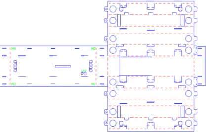
2.10 The 2D unfolded technical drawing file used for laser cutting where dashed red lines represent the folding edges and continuous blue lines show full cuts. The labeled parts are explained in detail in the text. . . 20
2.11 MinIAQ-II: A foldable miniature quadruped robot with indepen-dent leg actuation and improved mechanism design. . . 22
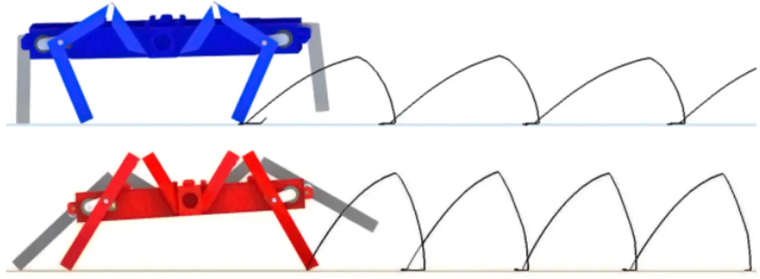
2.12 (a) Original locomotion mechanism trajectory of MinIAQ. (b) Op-timized mechanism trajectory of MinIAQ-II. . . 24
LIST OF FIGURES xv
2.13 A schematic representation of the unfolded to folded structure of the new leg design. The knee shaped triangular beam link consists of two triangular beams and a fixed angle joint that is locked in place with the help of the inclined fastener. . . 25
2.14 Comparison between forward leg trajectory for ideal trot gait sim-ulation of MinIAQ-II (top) and MinIAQ (bottom). . . 26
2.15 Estimation of pitch and roll angles variations from simulation at 3 Hz for both versions of MinIAQ. The snapshots on the right show the maximum recorded pitch and roll from actual tests. . . 27
2.16 Snapshots of MinIAQ-II’s improved maneuverability during a zero-radius in-position turning test at 3 Hz drive frequency. . . 28
2.17 The foldable, miniature, C-shaped-legged quadruped, C-Quad. . . 29
2.18 2D unfolded technical drawing of the body where blue lines repre-sent the full cuts and red lines reprerepre-sent the folding lines. . . 30
2.19 (a) The folded C-shaped leg. (b) Design iterations of C-shaped legs. 31
2.20 2D unfolded technical drawing of a C-shaped leg design. . . 31
2.21 Controlled steering of the C-Quad. . . 32
2.22 C-Quad locomotion over obstacle of 2.5 cm. . . 33
3.1 Force acting to the free end of cantilever beam with small deflections. 36
3.2 Moment acting to the free end of cantilever beam with small de-flections. . . 38
3.3 Force and Moment acting to the free end of cantilever beam with small deflections. . . 38
LIST OF FIGURES xvi
3.4 Moment acting to the free end of cantilever beam with large de-flections. . . 42
3.5 Combined force loads acting to the free end of cantilever beam with large deflections. . . 43
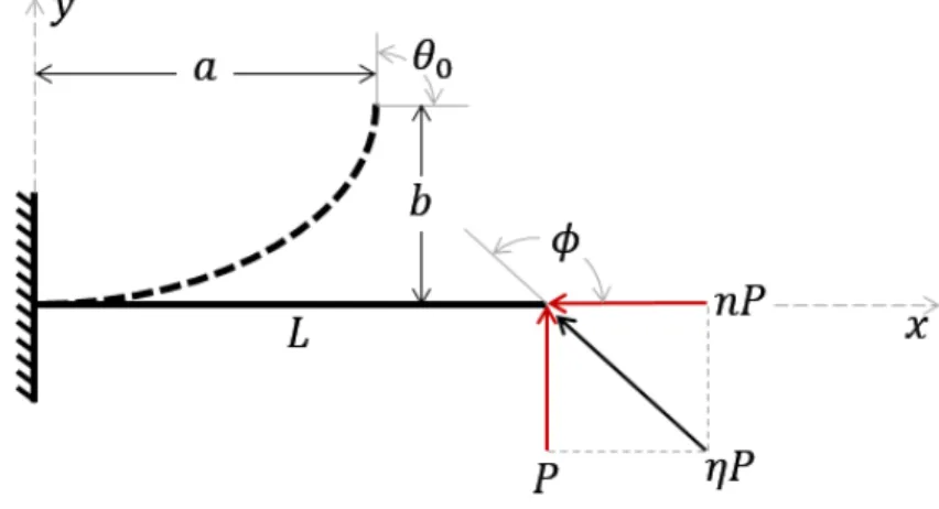
3.6 Combined force and moment loads acting to the free end of can-tilever beam with large deflections. . . 46
3.7 Initially curved beam with combined force and moment loads act-ing at the free end of cantilever beam. . . 51
3.8 End slope of joint, θ, versus vertical end load, P , for small and large deflection models. Joint parameters: L = 2 mm, b = 6 mm, t = 25µm, M0 = 0 N m and P = 0.001 N to 0.02 N. . . 53
4.1 A single leg compliant mechanism used in experiments to verify kinematic analysis. . . 55
4.2 (a) Free body diagram of rigid link CD. (b) Free body diagram of compliant joint. (c) Actuator link connected to motor, link AE. . 55
4.3 A single leg compliant mechanism with dashed lines to clarify trigonometric relation for prismatic joint. . . 56
4.4 A single leg compliant mechanism used in experiments to verify kinematic analysis. . . 57
4.5 Deflection angle of joint (θ) versus vertical end load (P ) experimen-tal average error (black), and kinematic analysis of large deflection elliptic solution (red). . . 58
4.6 Deflection curves of beam for linear elastic (blue) and nonlinear large (black) deflection models. Tip position is shown in red circles which is obtained from experiments. . . 58
LIST OF FIGURES xvii
4.7 Compliant mechanism used in MinIAQ-I. . . 59
4.8 (a) Free body diagram of first compliant joint. (b) Free body diagram of second compliant joint. (c) Free body diagram of link BC. (d) Free body diagram of link DF. . . 60
4.9 Free body diagram of the actuator link connected to motor, link GI. 61
4.10 Input crank angle (ψ) versus joint deflections (θ1 and θ2)
compar-ison for large deflection kinematic solution and FEA results. . . . 62
4.11 Input crank angle (ψ) versus joint end forces (P 1, nP 1, P 2 and nP 2) for large deflection kinematic solution. . . 62
4.12 Input crank angle (ψ) versus moments (M01, M02) and input crank
torque (Tin) for large deflection kinematic solution. . . 63
4.13 Compliant mechanism used in MinIAQ-II. . . 64
4.14 (a) Free body diagram of first compliant joint. (b) Free body diagram of second compliant joint. (c) Free body diagram of link BC. (d) Free body diagram of link DF. . . 65
5.1 2D planar stress element to 2D principal stress element transfor-mation. . . 69
5.2 Variation of bending stress subjected on PET sheet joint material used in early stages of MinIAQ-I design is a good example of cyclic softening. . . 73
5.3 Estimated S-N diagram for Kapton® polyimide film with param-eters σu = 231M P a, σe = 50M P a, Cn = 0.051 and mn= 0.28. . . 74
LIST OF FIGURES xviii
5.4 Time-stress reversal examples. (a) Completely reversed sinusoidal stress. (b and c) Sinusoidal fluctuating stresses with different mean stress (σm). . . 75
5.5 Modified Goodman diagram used to predict fatigue failure in fluc-tuating stresses. . . 76
5.6 Fatigue diagram for various criteria methods to to relate mean stresses (σm) to stress amplitude (σa) where σy is yield strength, σe
is endurance limit, σult is ultimate strength. Turquoise: Infinite
life area, Pink: Yielding area and Grey: Finite life area . . . 77
5.7 Estimated mean stress effect on the S-N diagram for Kapton® polyimide film for different mean stress (σm) and stress ratios (R)
with Parameters σu = 231M P a, σe = 50M P a, Cn = 0.051 and
mn= 0.28. . . 78
6.1 (a) Input small-length flexural joint mechanism. (b) Output opti-mized compliant joint mechanism. . . 84
6.2 Optimization convergence examples for MinIAQ-I mechanism for different thickness and stress amplitudes. (a) 75 µm (b) 100 µm Kapton® PI film. . . 84
7.1 Experiment setup used to obtain vertical force readings with the deflection of leg. . . 86
7.2 Vertical force (P ) versus end slope (θ0) for thicknesses of 25, 50,
75 and 125µm Kapton® PI film. . . 87 7.3 Input crank torque (Tin) versus end slope (θ0) for thicknesses of
LIST OF FIGURES xix
7.4 Vertical force (P ) versus end slope (θ0) for 2, 3, 4, 6 and 12 mm
long Kapton® PI film. . . 89
7.5 Input crank torque (Tin) versus end slope (θ0) for 2, 3, 4, 6 and 12 mm long Kapton® PI film. . . 89
7.6 Vertical force (P ) versus end slope (θ0) for 2, 4, 6, 8 and 10 mm wide Kapton® PI film. . . 90
7.7 Input crank torque (Tin) versus end slope (θ0) for 2, 4, 6, 8 and 10 mm wide Kapton® PI film. . . 90
7.8 Vertical force (P ) versus end slope (θ0) for vertical loads of 0.76, 3.08, 6.73 and 10.52 grams acting on the tip of the leg. . . 91
7.9 Input crank torque (Tin) versus end slope (θ0) for vertical loads of 0.76, 3.08, 6.73 and 10.52 grams acting on the tip of the leg. . . . 92
7.10 Limiting input crank torque experiment setup. (a) No load at-tached on the tip of the leg. (b) Vertical load atat-tached on the tip of the leg. . . 92
7.11 MinIAQ-I trajectory paths for compliant joint, small-length flexu-ral joint and revolute joint kinematic analysis methods. . . 94
A.1 Input mechanism of MinIAQ-1. . . 106
A.2 Optimized compliant mechanism of MinIAQ-1. . . 107
A.3 Input mechanism of MinIAQ-2. . . 108
List of Tables
7.1 Torque limit experimental versus large deflection kinematic predic-tion results when no loads acting to tip of the leg (see Figures 4.1 and 7.10(a)). . . 93
7.2 Torque limit experimental versus large deflection kinematic pre-diction results when vertical force is applied on the tip of the leg (Dy = 1.7g see Figures 4.1 and 7.10(b)). . . 93
Chapter 1
Introduction
1.1
Objectives and Contributions of the Thesis
The first contribution of the work on this thesis is the design, development, and basic operation of MinIAQ-I, MinIAQ-II and C-Quad, which are origami-inspired, printable, miniature quadruped robots. Instead of employing multi-layer compos-ite structures similar to most micro-robotic fabrication techniques, these robots are fabricated from a single A4 PET sheet. MinIAQ-I and MinIAQ-II leg mecha-nisms are designed as compliant mechamecha-nisms based on simple four bar mechanism and C-Quad is designed based on C-shaped wheeled legs that are separately man-ufactured by folding C-shaped wheels. Each four legs of these robots are driven and controlled separately by DC motors and encoders enabling gait modification and higher degree of freedom on controlling the motion. The origami inspired fab-rication technique is a fast and inexpensive method to make complex 3D robotic structures through successive folding of laser-machined sheets. However, there is still a need for improvement in modulating and extending the design standards of origami robots. In an effort to addressing this need, the primitive foldable design patterns of MinIAQ for higher structural integrity and rigidity are presented in detail.
The foremost contribution of this thesis is the optimization of the compliant joints used in but not limited to the miniature robots discussed above. The flexure joints used in compliant mechanisms are modeled as cantilever beams fixed from one end and subjected to combined end loads and moments based on nonlinear large deflections. There exists several methods to predict the deflection of the cantilever beams, such as FEA methods, but they are time consuming and hard to solve based on optimization problem. In this work, elliptic integrals are used to solve the large deflections of Bernoulli–Euler cantilever beams, which are easier to converge to a solution and have high accuracy for thin beams. The biggest challenge in using a compliant joint in these mechanisms is the fatigue failure of these flexure members. The fatigue failure methods are investigated for combined loading conditions, then the compliant mechanisms used in MinIAQ are optimized for desired output trajectory and fatigue cycle life. Using the work in this thesis one can obtain the maximum load capacity, input motor torque required to actuate the loaded mechanism and number of cycles before failure of a compliant mechanism.
1.2
Organization of the Thesis
Chapter 2 focuses on the design of MinIAQ, the miniature quadruped, which was inspired by origami, the traditional Japanese art of subsequent folding of a 2D sheet into a 3D functional structure. Folding is an efficient and simple approach to planar fabrication of flexible 3D structures and can be employed as an alternative fabrication method to traditional machining or complex composite manufacturing processes. Yet, it is not extensively utilized in engineering fields due to its limiting factors such as planar design constraints, material selection limitations, and relatively complex folding and assembly tasks involved.
Chapter 3 introduces the beam theories used to model compliant joints. Firstly, advantages and challenges in using compliant joints are explained. Then, linear elastic beam deflection models are derived, which give accurate results for small
deflections. Since compliant joints used in miniature robotics undergo large de-flections, linear elastic beam theories yield high error. For this reason, nonlinear large deflection methods are used to model joints in compliant mechanisms. A brief historical background survey about nonlinear large deflection beam theories is provided based on different methods. Among the readily available methods, el-liptic integral solution for nonlinear large deflections is chosen for different loading conditions.
In Chapter 4 kinematic model of compliant mechanisms will be presented, which has a different approach than traditional revolute joint kinematic analysis and harder to solve. In order to model the kinematics of a compliant mechanism, the nonlinear large deflection elliptic integral solutions introduced in Chapter 3 are combined with static equilibrium equations of rigid linkages and loop closure equations based on free body diagrams of a compliant mechanism. The first mechanism introduced in this chapter is relatively simple four bar mechanism, which has a single compliant joint, used to verify the validity of results obtained in large deflection elliptic integral solution. The vertical force obtained from large deflection elliptic integral kinematic solution of this simple mechanism is verified with Comsol FEA and experimental results. Finally, large deflection elliptic integral kinematic analysis is done based on compliant mechanisms used in MinIAQ-I and MinIAQ-II and output trajectories are obtained. The large deflection elliptic integral kinematic analysis and FEA results for end slopes and forces acting on compliant joints are presented.
Chapter 5 investigates the methods to prevent the fatigue failure of compliant mechanisms. First the planar stresses subjected to a compliant joint are discussed for different loading conditions, then principal stress is explained which are key elements in dealing with fatigue failure for combined loads. A fatigue-life method will be presented that provides an insight on stress-life cycle for polymers based on mathematical formulations.
Chapter 6 provides an optimization method for joints used in compliant mech-anisms. First, an appropriate optimization algorithm is chosen from MatLab
optimization toolbox. fminimax multi-objective nonlinear constraint optimiza-tion funcoptimiza-tion is used. Then, optimizaoptimiza-tion problem is defined for MinIAQ-I leg mechanism and optimization is conducted for this mechanism.
In Chapter 7, experimental results are presented for the effect of changing geo-metric parameters of a compliant joint. Results are plotted for varying a single geometric parameter while other parameters are kept constant. Discussions are made for effect of each parameter on force acting on the leg and input torque required to drive the mechanism.
Chapter 8 is a summary of this thesis and provides the conclusion and outlook of the current work, including any improvements possible and future works for the content of this thesis.
Chapter 2
Design and Manufacturing of
MinIAQ
In this chapter, design, development, electronics and basic operation of MinIAQ, which is inspired by origami art, the traditional Japanese art of subsequent folding of a 2D sheet into a 3D functional structure is presented. Then, MinIAQ-II, which has an improved locomotion design is presented and its improvements are explained. Finally, C-Quad, which has C-shaped wheels, wheeled legs, instead of legs is introduced and its benefits are explained.
2.1
Historical Background of Miniature
Fold-able Robots
Miniature and small scale robotic applications offer solutions to accomplish low cost and high modularity that macro robotic applications generally remain inca-pable, which additionally limits the widespread utilization of macro scale robots. Moreover, unlike macro scale, miniature robotic systems have important advan-tages such as, nimbler locomotion, high maneuverability abilities that allow them to access confined and hazardous spaces [1]. On the other hand, miniature scale
applications generally have locomotion, slip, design and failure limitations. Flex-ure joints used in compliant mechanisms have a maximum allowable deflection, while revolute joints can rotate unlimited number of times, so these mechanisms have limited rotation range and reachability. Since rotation of these joints comes from bending of flexure segments, bending stresses may cause failure under long period of cyclic loads. Also a proper design is needed to assemble such mechanism to achieve rigidity and integrity to carry desired loads.
In literature there exists several methods for miniature robotic design and fab-rication such as MEMS [2, 3], cutting laminate of carbon fiber composite and thin polyimide films (SCM), 3D printing [4] and folding [5–7], such as used in RoACH [8] and HAMR [9].
Kirigami, a subset of origami involving out-of-plane cuts [10], inspired developing a new planar fabrication process for micro-robotic systems which is often referred to as printable, foldable, or print-and-fold robotics [11]. In this context, the term printing corresponds to engraving cut and fold patterns on sheets by utilizing a laser cutter or even by patterning 2D printable layers using 3D printers [12]. One of the advantages of printable or foldable robotics is that all transmission, flexure joints, and customizations can be embedded into a single 2D design, which not only is cheap and time-saving, but also eases the fabrication, assembly, and future design enhancements. Following the early works reported in [13], this technology was first developed by researchers in Harvard University and MIT [11] and was later adapted by many researchers in designing their miniature grasping [14, 15], flying [16], and worm type robots [17,18] as well as some enhanced legged versions [19–21]. The method was further developed in [22] by implementing embedded circuitry through shape-memory composite planar designs to enable self-folding of the robots.
Despite the recent advancements in foldable robotics, there exists space for devel-opment in standardizing the hierarchical design process and folding elements to obtain high structural integrity and rigidity in a robotic platform. There aren’t many examples of complex foldable structures and most of the works rely on rather simple designs. This chapter aims to design MinIAQ in a way to show
the capability of this fabrication method for making complex robots and set a paradigm for designing more complicated foldable structures with higher struc-tural integrity and rigidity.
MinIAQ is a quadruped foldable legged robot made from a single sheet of thin A4-sized PET film. The stiffening structures used in the robot and the overall unfolded structure design are not presented before, and thus this is one of the contributions done to the literature. As another contribution of this work, each leg is designed to be actuated individually by a small DC motor. This is different from previous miniature robots where one or two actuators are shared between legs to provide easier synchronous leg motion. Despite higher power consumption and greater challenge in phase synchronization control at such small scale, the idea of using one actuator per leg is to independently control the legs, achieve better maneuverability and in-place sharp turning, and have higher degree of freedom on controlling the overall robot’s motion.
The main reason in designing a robot with individually actuated legs is not to claim that it is better or easier to control than miniature robots with coupled actuation but to enable gait modification during locomotion in a small scale for future studies. As an additional contribution, custom absolute encoders are designed for having small-yet-sensorless actuators to generate a single predefined signal that could be used to estimate both the speed and position of each leg and synchronize the legs accordingly. Even though the current version is a quadruped, the robot can be modified to have ‘n’ legs, if ‘n’ of these individually actuated legs are put together on a single body.
2.2
Design of MinIAQ
MinIAQ is fabricated from a single sheet of thin A4-sized PET film. Its legs are designed based on a simple four-bar locomotion mechanism that is embedded within its planar design. Each leg is actuated and controlled individually by separate DC motors enabling gait modification and higher degree of freedom on
controlling the motion (see Figure 2.1).
Figure 2.1: Foldable miniature quadruped robot, MinIAQ.
The origami-inspired fabrication technique is a fast and inexpensive method to make complex 3D robotic structures through successive-folding of laser-machined sheets. However, there is still a need for improvement in modulating and extend-ing the design standards of origami robots. In an effort to addressextend-ing this need, the primitive foldable design patterns of MinIAQ for higher structural integrity and rigidity are presented in detail.
The initial version of the robot takes less than two hours to be cut and assembled and weighs about 23 grams where 3.5 grams is the weight of its body, 7.5 grams is its motors and encoders, 5 grams is its battery, and about 7 grams is its current on-board electronics and sensors. The robot is capable of running about 30 minutes on a single fully charged 150mAh single cell LiPo battery. Using the feedback signals from the custom encoders, MinIAQ can perform a trot gait with a speed of approximately 0.65 Bodylengths/sec, or equivalently 7.5 cm/s.
2.2.1
Material Selection
In designing MinIAQ, the aim was to make an embedded single-piece crease pattern for ease of manufacturing. In order to select a proper material in terms
of flexibility, rigidity, and joint durability, 100, 250 and 500 micrometer thick PET sheets were selected as possible candidates, see Figure 2.2. During the manufacturing process, it was observed that the thinner sheets were easier to cut, fold and assemble. Despite the fact that rigidity increases with film thickness, it becomes harder to make folds and shape corners, especially by scaling down to smaller scale folds. In addition, the thicker sheets had lower joint performance since the joints made of thicker sheets would plastically deform and break much sooner than the thin sheets, which makes sense according to beam theories that will be explained in Chapter 3. Alternative structural materials can also be used to achieve enhanced mechanical properties such as increased stiffness or higher joint cycle life. Chapter 6 deeply focuses on these issues to achieve higher joint life cycle.
Figure 2.2: Various colors of PET sheets used in MinIAQ as structural material.
2.2.2
Actuation Mechanism and Leg Design
In MinIAQ, rigid triangular beams and compliant flexure joints are used as the primitive components of the locomotion mechanism (Figure 2.3). Rigid triangular beams are achieved by folding the sheets and locking into triangular prism shape. In this configuration, the beam’s rigidity is dependent on its length, width, thick-ness and Young’s modulus of material used [23]. Flexure joints are kinematic components that allow rotation in 1 DOF between two rigid links with the help
of sheet flexibility. Even though flexure joints are very useful components for miniature scale compliant mechanisms, they suffer from fatigue failure [24]. By optimizing the joint width, length and maximum deflection angle, life cycle of the flexure joints can be increased further by distributing the load more uniformly and reducing the stress at the joints. At the time that the initial version of the MinIAQ was designed, the joints were not optimized yet, but this issue will be dealt later on Chapter 6.
Figure 2.3: Gait trajectory of the cam-driven four-bar mechanism with a detail view of the fundamental linkage and joint design in foldable robots. Inset shows hollow triangular beams with flexure joints.
The first step towards a legged robot design and perhaps the foremost important stage is the design of its actuation mechanism. In foldable robotics context, it is quite challenging to integrate a mechanism into the design which has good locomotion trajectory while having simple unfolded form. The flexure joints in foldable designs have limited degree of rotation, meaning that the links should not be bent very large with respect to each other so as to prevent shear at the joints [25]. This issue further aggregates the challenge in mechanism selection.
For MinIAQ’s legs, a simple four-bar cam-driven mechanism was designed and synthesized by altering the dimension of the leg, position of the joints and radius of the cam (input crank link) in order to obtain an acceptable gait path as shown by the trajectory in Figure 2.3. The selected four-bar is not optimal performance-wise; it has relatively poor gait path and stride length. However, its simplicity was favored over complexity for the initial MinIAQ version due to ease of planar design and assembly. In improved version of MinIAQ, a more optimal transmission is used, which will be introduced in Section 2.4 of this chapter.
2.2.3
Design Elements for Higher Frame Stiffness and
Rigidity
A very important parameter influencing the payload capacity of a foldable robot is its structural integrity. Due to having a thin flexible sheet as the base material, certain primitive folded structures were required to make the frame and linkages hold their shapes. These primitive folded components set the basic design rules and act as subsets of any complex structure. As discussed, the legs were designed according to the hollow triangular linkage and perforated joint structures studied in the literature by [19, 23, 26, 27].
As an addition to the foldable robot design library in the literature, newly intro-duced T-shaped folds are used as fundamental elements in MinIAQ contributing to its high structural integrity (shown in green in Figure 2.4, 2.5, and 2.6). They act as out of plane extensions which not only stiffen the main robotic frame, but also can restrict transverse bending, buckling and belling of the robot. To lock the T-shaped folds in place, gluing or stitching can be a solution, but they are practically hard to implement for small parts and tiny extensions. The better approach is to utilize tab-and-slot fasteners to tightly lock the parts into each other.
On every T-fold, certain tabs are placed on one of the faces that locks into a slot. To firmly fix the position of a pair of T-folds and hold them in place with respect to each other, the tabs on each T-fold should be fastened into a single slot (see Figure 2.4(a)). Once the tabs are inserted through the slot, sides of the tabs are bent into U-shape to achieve proper locking in place as seen in Figure 2.4(a). The visual representation of locking mechanism for T-folds can be seen in Figure 2.5 with red color. Note that a total of six (three on each side), equally spaced, double-sided T-fold fasteners are used on the main frame of MinIAQ. By using such fasteners, T-fold assemblies can be completed in minutes without needing any extra effort or hand skill.
(a)
(b) (c)
Figure 2.4: (a) Unfolded crease pattern of two parallel T-shaped folds (green) with embedded U-shaped fasteners (red). The black dashed lines represent the folding lines. (b) Folded structure of T-folds with their U-shaped extension tabs fastened into a common slot in between. (c) Side view of the folded structure showing how the fasteners pass underneath the T-folds and lock into the slot from below.
dislocations, extension tabs (shown in yellow in Figure 2.5) were made at the ends of the T-folds, which are tightly fitted through a slot. The friction between the extension tab and slot has enough locking force to prevent sliding of tabs due to torsion and any movement along the transverse direction. These tabs can be converted to U-shaped lockable tabs introduced in the next paragraph to achieve better locking but with slightly harder assembly.
To further improve the bending stiffness of the main frame, the T-folds located within the body are attached to the top cover of the main frame using two types of fasteners. The first type is the tight fit extension tabs and slots described in preceding paragraph that prevent buckling of T-folds by tight fitting the tabs on the upper side of the T-folds into a slot on the top cover (Figure 2.5 - pink). The second type of fastener used to stiffen the main frame is U-shaped lockable tabs, which are practically tabs with foldable extensions on both sides that form a U-shape after inserting through a slot and folding the extensions inwards by 90◦ (Figure 2.5 - blue). By fastening the U-shaped tabs on the T-folds through the slots placed on the top cover, fixing the T-folds rigidly in place is achieved that they act as I-beam like structures. Therefore, by using ‘n’ number of T-folds within the structure and using tabs and U-shaped fasteners, the main frame
technically becomes a rigid body supported by ‘n’ number of I-beams.
Figure 2.5: A sectional view of MinIAQ’s main frame with tight fit motor housing using a pair of parallel T-folds and an IR sensor housing on the outer T-fold next to motors. Green: T-shaped folds. Red: Double-sided coupled locking tabs to fasten T-fold faces. Yellow: T-fold end extension fasteners to restrict torsional twist and sliding dislocations (Holes are used to temporarily insert pins during assembly). Pink: T-fold top extension fasteners to restrict torsional twist and sliding dislocations. Blue: U-shaped lockable fasteners to form I-beam like structures from T-folds.
Another challenging stage in the design was to find a folded structure to tightly hold the DC motors in place within the frame. Note that while using an external housing could be a solution, in foldable robotics the aim is to avoid using separate parts or materials as much as possible and restrict the work to a single uniform crease pattern. This was solved by using two sets of parallel T-folds on each side of the main frame and placing tight circular housings for the DC motors through each pair. T-folds increased the rigidity of the frame and also held the motors strongly in place. Thus, due to their out-of-plane structure, T-folds are very suitable for making housings such that any type of motor can be properly mounted onto the frame by a pair of parallel T-folds. Since MinIAQ is designed to have individual leg actuation, four T-folds were embedded into the design to enable four motor housings, one at each corner of the frame (Figure 2.5 and 2.6).
The rotational motion of the motors was transmitted to the legs with a cam shaft made of a thicker sheet film. Note that since the cam shaft, i.e. the crank link of the four-bar, has to rotate 360◦ in plane, it is very hard and complex, if not
(a) (b)
Figure 2.6: (a) Unfolded structure of two T-folds with motor and sensor housings. The black dashed lines represent the folding lines. (b) Folded structure of T-folds with motor and sensor in place.
impossible, to achieve this with an origami flexure joint structure. Thus, the cam shafts were made and assembled from separate sheets and pins. These elements on the MinIAQ are the only mechanical structures on the robot that have to be manufactured separately. The cam shafts also serve as elements used in control and synchronization of the robot legs via IR sensors which are explained in detail in Section 2.2.5 of this chapter. Placing the sensors on the body is achieved by making a small housing next to the motors and inserting them within the outer T-folds. A small rectangular opening for the emitter and receiver on the outer side of the T-fold helps holding the sensor in place by preventing it from sliding inside the T-fold that can be seen in Figure 2.6.
2.2.4
Design of Electronics and PCB
With the intention of independent actuation of each leg, MinIAQ is designed with four very small and lightweight (approx. 1.25 grams each) motors (Pololu, Sub-Micro Plastic Planetary Gearmotor). The major drawback of using these motors is the lack of any type of built-in encoders. For this reason, it is necessary to design a feedback controller for each motor to properly adjust the speed and position of each leg. Therefore, small IR sensors are selected to house next to the motors and custom cam encoders with black and white stripes are made and attached to the motors.
The IR sensors need three connections (power, ground and signal) to operate in order to provide feedback signal to the controller. To avoid complex wiring
(a) (b)
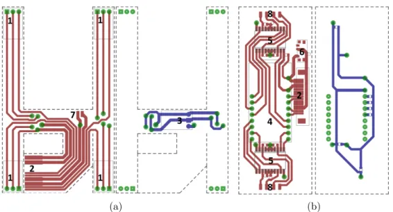
Figure 2.7: CadSoft Eagle drawing of the PCBs used in MinIAQ: (a) Inner flexible PCB for sensor connections and power regulation and distribution. (b) Main controller PCB for controls and driving the actuators. Red color lines show traces on top layer and blue color lines show traces on bottom layer. The labeled numbers indicate the soldering position of components and connectors described in text.
and soldering of each sensor, a flexible PCB that will be located inside the body frame is designed, which can be cut into shape and extended to the sensors. This inner flexible board powers every sensor and transfers the signals to the controller (see Figure 2.7(a)). A copper clad polyimide flexible sheet is chosen as the PCB material (Dupont, Pyralux). The inner flexible PCB interconnects the two sensor couples by two 90 degree folds (Figure 2.7-1). Signal and power traces of the inner PCB are combined and bundled in a foldable extension that comes out of the top frame, to be connected to the main controller PCB, which is located on top of the robot, through a socket (Figure 2.7-2).
To run the robot, a single cell 3.7 V, 150 mAh LiPo battery is used and it is soldered from the pads seen in Figure 2.7-7. Then its voltage is boosted to 5 V with a step-up regulator located on the inner flexible PCB (Figure 2.7-3)) to power the sensors, the motor drivers, and the microcontroller.
The Arduino Pro Micro microcontroller (Figure 2.7-4) is placed on the main controller PCB located on top of the main frame, along with two L293DD motor
driver ICs (Figure 5), 16 SMT capacitors, on-off slider switch (Figure 2.7-6) and an FFC/FPC socket (Figure 2.7-2) to connect the inner flexible PCB to the main controller PCB. The main controller PCB can be seen in Figure 2.7. The inner flexible PCB distributes the regulated 5 V power to the sensors and the main controller PCB and also transfers the signals generated by the sensors. Finally each motor is soldered via the pads placed on top and bottom of the main PCB (Figure 2.7-8).
2.2.5
Custom Encoder Design and Control Input Signal
Considering the choice of having four actuators on board, one of the smallest and lightest available DC motors was selected as the actuator. However, these motors lack extension shafts for encoder attachments. For determination and control of both speed and position of each leg, small analog IR sensors were selected as MinIAQ’s only sensing device and were embedded into the design next to the motors as explained in Section 2.2.3 of this chapter.
An absolute encoder with a single black band was designed and integrated with the actuation mechanism cam-shaft (crank linkage) as shown in Figure 2.8(a). The output signal of this cam resembles a single peak per cycle signal where for a walking motion with nominal frequency of about 2.5 to 3 Hz, it does not provide more than a few discrete inputs in each cycle to the controller. Thus, during walking trials, it was observed that the speed of the control loop was insufficient to compensate for the highly varying loads on the motors.
In an effort to increase the number of sampled data inputs and rate of control, a 3D encoder cam shown in Figure 2.8(b) was designed. Due to the sensitivity of IR sensors to distance, the amplitude of the peak for the gray band becomes noticeably smaller than those of the black bands. By this means, the position of the legs over the entire cycle can be estimated based on the smaller peak reference. Figure 2.8(c) represents the analog output signal of the 3D cams with 28 detected discrete input data points that are used for motors’ speed control and phase synchronization. Note that to obtain a 180◦ phase difference between the
diagonal leg pairs, only the position of the crank pin holes on each encoder pair are placed with 180◦ offset. Thus, by synchronizing the signals of all four cams to have zero phase, 180◦ phase difference was ensured on the legs resembling the ideal trot gait locomotion.
(a) (b) (c)
Figure 2.8: (a) Single black band cam shaft encoder. (b) 3D cam shaft encoder. (c) A 3D encoder analog output signal with 28 sample points detected per cycle for the controller input.
2.3
Fabrication and Assembly
2.3.1
Fabrication of Electronics and PCB
Before starting the assembly process of the robot, boards introduced in Sec-tion 2.2.4 must be fabricated and components must be soldered. The PCBs are manufactured by coating a mask material on the flexible sheets, ablating the coat-ing with a laser engraver (Universal Laser Systems, VLS 6.60) in raster-scan mode to generate the appropriate mask, and etching the copper at the unmasked loca-tions. Since the board material used is a thin flexible sheet, it must be flattened perfectly and bonded to a flat surface to prevent any wrinkles during ablation process.
Prior to coating the mask material, the surface is cleaned from dust and oils. After initial cleaning, the surface is coated by using a dark, varnish-based paint.
Afterwards, the mask material is ablated with a laser engraver to form a positive mask. Unmasked copper regions are then etched using HCl3 solvent and the
PCB traces remain with mask material on them. The remaining mask material is cleaned with acetone and finally components are soldered to the boards using solder paste and a heat gun. The whole process takes about 4 to 5 hours due to the slow speed of laser raster, relative complexity of the circuits, and the number of components that needs to be soldered, see Figure 2.9.
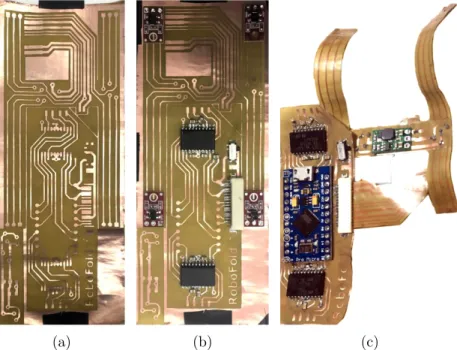
(a) (b) (c)
Figure 2.9: (a) PCB without any components soldered. (b) PCB without Arduino Microcontroller soldered. (c) PCBs final state after all components soldered, cut and folded ready to be inserted inside the robot.
The PCB used on MinIAQ has an Arduino Pro Micro controller that drives the four DC motors through two L293DD H-bridge motor drivers. A 3.7 Volts 150 mAh battery is placed inside the robot’s body. Using a step-up regulator its output is boosted to 5 Volts to power the main board, motor drivers and sensors. The completed MinIAQ is approximately 6 cm in width, maximum of 4.3 cm in height, and about 12 cm in length. In the absence of any components, the folded structure weighs only 3.5 grams. The DC motors add a total of 5 grams and the PCB, electronic components, battery, and encoders add an extra 14.5 g to the platform making the weight of the current MinIAQ approximately 23 grams.
Once the electronics are ready, the robot’s body is fabricated and assembled. The PET sheets are cut in the same laser engraver used in manufacturing of the PCBs. The assembly stage consists of consecutively folding and fastening the T-folds, placing electronics and motors inside, closing and fastening the sides and the top cover, and folding the legs, which is explained in detail in the next section.
2.3.2
Fabrication and Assembly of the Robot
This section explains the fabrication process of MinIAQ from scratch which takes less than two hours to cut and assemble. The process begins with laser cut-ting (using Universal Laser Systems VLS 6.60) of the unfolded design from thin PET sheets which takes about 20 minutes. The design of MinIAQ was done in AutoCAD and its technical drawing cut file is shown in Figure 2.10.
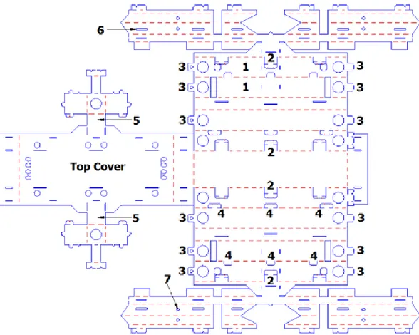
The first step in assembling MinIAQ is folding the T-shaped folds. T-folds are labeled as 1 in Figure 2.10. Once every four T-folds are folded, the IR sensors are placed inside their housing within the outer T-folds and wired to the PCB. Next, the T-folds are fastened by using double-sided tab and slot fasteners (Figure 2.10-2) explained in Section 2.2.3 of this chapter. After that, motors and sensors are placed into the housings that are located on the corners of the T-folds. Then, the extension tabs labeled as 3 in Figure 2.10 are attached to the front and back of the main frame and are temporarily locked in place with small pins.
The top cover of the main frame is folded on top of the T-folds after passing the sensors and motor wires through the holes placed on the top cover. Once done, the tabs and U-locking fasteners existing on top of the T-folds (Figure 2.10-4) are fastened to the top cover one by one.
Once the main body frame is enclosed, the supports carrying the load on the legs, shown in Figure 2.10 labeled as 5 are assembled for increased rigidity. These supports consist of the same tab-and-slot and locking mechanisms explained in Section 2.2.3 of this chapter.
Figure 2.10: The 2D unfolded technical drawing file used for laser cutting where dashed red lines represent the folding edges and continuous blue lines show full cuts. The labeled parts are explained in detail in the text.
Prior to assembling the legs, wiring and placing electronic components should be done to avoid harming the flexure joints. Next, the legs are folded and their fasteners are locked to form rigid triangular beams.
During the assembly process, positioning some of the interior extensions and locking U-shaped fasteners can be challenging. Introducing some slots such as the one labeled as 6 in Figure 2.10 can help overcome this problem. With the help of these slots, one can access the fasteners easily with tweezers or a similar hand tool. Then, the cams are attached onto the DC motors’ shafts and connecting the legs and cams by inserting a pin through the pin holes (Figure 2.10-7).
2.4
Improved Latest Version, MinIAQ-II
The originally designed first version of MinIAQ with individually actuated legs is relatively slow [5] and it cannot maneuver properly due to the easy-to-make leg mechanism which has a poor trajectory. Through designing the first version of the robot, the experience gained on mechanism design for foldable robots have been used to create an improved foldable mechanism for higher traction and better stability. The improved mechanism requires links that are not flat, essentially joints that are fixed to a specific angle. In this section, these design enhancements are demonstrated, as well as the new version of the robot, MinIAQ-II is presented [6].
The major contributions done on this section are the enhanced easy-to-fold four-bar leg mechanism design of the new version of MinIAQ as well as a systematic approach to create non-straight rigid foldable links, i.e. link designs with fixed-angle joints in the middle. It is believed that the novelties in the design of foldable structures in the original and new version robots can be applied to similar foldable or conventional microrobots and mechanisms.
Like its predecessor, the new version of the robot, named MinIAQ-II (see Fig-ure 2.11), weighs 23 grams, is 12 cm in length, 6 cm in width, 4.5 cm in height, and can walk forward with a speed of more than 0.8 bodylengths/sec at 3 Hz stride frequency. Having optimized the actuation mechanism trajectory and ob-served comparable performance improvements of MinIAQ-II, this robot can be used to perform gait studies in miniature scale robots.
2.4.1
Linkages, Flexure Joints and the Main Body Design
In MinIAQ-II, 100-micrometer-thick PET sheets, same as the material used in the original MinIAQ [5], are used as the main structural material. To create kinematic chains, the well-known compliant flexure joints and triangular rigid beams are utilized. Most of the kinematic chain uses the conventional foldable
Figure 2.11: MinIAQ-II: A foldable miniature quadruped robot with independent leg actuation and improved mechanism design.
robot links and joints. However, this easy-to-make, straight rigid link shape has to be altered into a non-straight link for one of the links in the kinematic chain to improve the trajectory of the mechanism. Details on the kinematic analysis and the non-straight link fabrication are given in sections Section 2.4.2 and 2.4.3 of this chapter.
Due to the nature of foldable robot fabrication that employs a single thin sheet of material as the main structural element, integrity of the main frame and rigid linkages are very important. To achieve a reasonable degree of structural integrity, several types of tab-and-fastener locking mechanisms were embedded into the original design.
In the original MinIAQ design, T-folds were introduced to increase bending stiff-ness of the main frame of the body, U-shaped fastener tabs to keep the folded structures locked, and tight fit tab-and-slot fasteners to block sliding dislocations on structure planes. The T-folds are created as a crease pattern of three parallel lines on the main frame part of the sheet. When the three parallel lines are folded inwards 90 degrees, outwards 180 degrees, and outwards 90 degrees, respectively, they form a T-shaped structure in the body [5]. If T-folds, U-fasteners and tight fit tab-and-slots are used together in right spots, the T-folds become I-beam like structures and the main body frame enclosure becomes very stiff; it does not bend, twist, or buckle during operation (see Section 2.2.3). In the new version of MinIAQ, all of these structural elements are used very similar to the first version.
2.4.2
Locomotion Mechanism Optimization
The original easy-to-fold four-bar leg design in MinIAQ has a relatively poor trajectory, therefore, the robot is quite bouncy and slow [5]. Essentially, a flatter and more elliptical trajectory is needed in order to maximize the lateral motion during ground contact and reduce the bounciness. Altering the straight coupler link into a knee-shaped link, as can be observed in many animals, can shift the trajectory of the tip of the leg more in parallel with the ground. But this alteration is not straight-forward due to restrictions of the manufacturing process and 2D unfolded design complexities. Thus, the simplest solution to tackle a non-straight rigid link design is to make a fixed-angle locking joint and incorporate that to the coupler link design.
Position-based optimization methodology is employed to determine a set of design parameters for the best achievable trajectory for this specific four-bar leg design. In optimizing the mechanism, certain criteria and design constraints are imposed. The algorithm is to carefully define regions in which each individual node can be relocated incrementally such that the resulting leg trajectory is as close as possible to the ideal trajectory. The optimization algorithm seeks for the best set of design variables that minimizes the cost function, being the least square error between the resulting tip trajectory and the ideal desired trajectory. Figure 2.12 illustrates the trajectories of the final configuration of the optimized mechanism as well as the trajectory of the original MinIAQ’s mechanism. With the resulting mechanism, MinIAQ-II benefits from a longer stride length, improved lateral ground contact, smaller leg lift (bounciness), and less flexure joint bending.
2.4.3
Fixed-Angle Knee Joint Design
The implementation of the enhanced mechanism requires an unfolded crease pat-tern to precisely obtain a required fixed angle lock between two triangular rigid beams. There are examples of non-straight members such as in gripping structure of [19] in literature. However, no detail is given on how to systemically design
(a) (b)
Figure 2.12: (a) Original locomotion mechanism trajectory of MinIAQ. (b) Op-timized mechanism trajectory of MinIAQ-II.
and control the locking angle of such rigid bent links, therefore implementing similar designs for other researchers are very hard. For this reason, many design iterations are done to get a rigid-enough locking mechanism at any desired design angle specified.
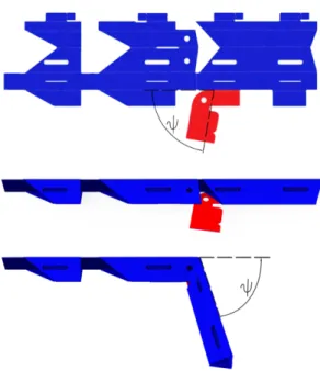
The majority of the changes in MinIAQ-II design, compared to the original MinIAQ, comes from its optimized leg mechanism shown in Figure 2.12. How to fold a single leg in two main steps to form the final shape is illustrated in Figure 2.13. The proposed design for the knee-shaped link consists of two regular triangular beams connected with a short flexure joint and an inclined fixed-angle tab-and-fastener locking mechanism next to it. Note that the angle between the inclined fastener and the leg orientation on the unfolded structure is equal to the resulting desired fixed-angle lock between the folded beams.
With the proposed design, any two triangular beams can potentially be locked together at any desired acute or obtuse angles. If one requires to lock the right portion of the leg with a downwards orientation, similar to MinIAQ-II, the trian-gular beams can be folded in the reverse direction and the locking mechanism can be placed accordingly to be folded and locked in reverse. In the original MinIAQ, the triangular beams have been folded upwards, but they are folded downwards in MinIAQ-II to enable the 81◦ fixed-angle lock.
Figure 2.13: A schematic representation of the unfolded to folded structure of the new leg design. The knee shaped triangular beam link consists of two triangular beams and a fixed angle joint that is locked in place with the help of the inclined fastener.
2.4.4
Performance of MinIAQ-II
MinIAQ-II’s performance on straight walking and turning are tested in several experiments and the new version’s performance is compared to its predecessor. MinIAQ-II can run about 30 minutes on a single fully charged 150mAh battery and the flexure joints last a few hours of constant operation before fatigue failure. The kinematic simulation of an ideal trot gait driven at 3 Hz (Figure 2.14) is done in SolidWorks for both versions of the robot with correct physical and material properties. While the robot has shown successful performance at different stride frequencies, it is generally run at 3 Hz for tests and simulations because MinIAQ-II achieves a more natural and stable quadrupedalism behavior at 3 Hz stride frequency.
Figure 2.14: Comparison between forward leg trajectory for ideal trot gait simu-lation of MinIAQ-II (top) and MinIAQ (bottom).
Simulation results show the new version’s superiority over the original MinIAQ. The results not only imply larger stride length, but also suggest a more stable walk due to smaller leg lift. Several experiments are conducted to verify the performance increase suggested by the simulations. The experiments demonstrate an increase in average forward locomotion speed from 0.65 bodylengths/s (7.5 cm/s) in original MinIAQ to more than 0.8 bodylengths/s (9.7 cm/s) in MinIAQ-II.
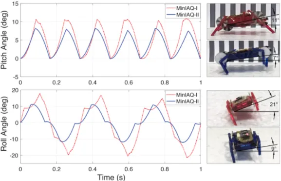
Figure 2.15 shows the simulation results of pitch and roll angle variations at 3 Hz-drive, together with snapshots of experimental results for maximum pitch and roll. The experiments are in good agreement with the simulation results. Due to the improved mechanism, MinIAQ-II has a more stable walk and much better maneuverability due to an approximate decrease in body’s roll from ±21◦ to ±9◦ and a lower pitch angle of 0◦-7◦ compared to the original MinIAQ’s 0◦-11◦ pitch.
Figure 2.15: Estimation of pitch and roll angles variations from simulation at 3 Hz for both versions of MinIAQ. The snapshots on the right show the maximum recorded pitch and roll from actual tests.
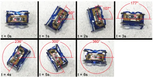
The relatively better stabilization and balance in locomotion of MinIAQ-II helps the robot to have a more uniform load distribution on its feet. This uniform load distribution results in improved maneuverability of MinIAQ-II, where its predecessor lacks the most. The feet of the previous version of the MinIAQ cannot keep traction properly due to the varied load distribution and results with an in-place turning with an inconsistent angular speed and low success rate. On the other hand, MinIAQ-II can successfully turn in-place in every trial with an almost constant angular speed. Figure 2.16 shows the capability of the robot to turn in-place with a speed of 60◦/s at 3 Hz motor frequency.
Figure 2.16: Snapshots of MinIAQ-II’s improved maneuverability during a zero-radius in-position turning test at 3 Hz drive frequency.
2.5
C-Quad and C-Shaped Wheel Design
In the design of the C-Quad, the aim was to use a leg design that would pro-vide the robot a high mobility. Originally, RHex showed impressive rough terrain locomotion capabilities using C-shaped compliant legs [28]. More recently a sim-ilar leg design is implemented by Maryland Microrobotics Laboratory on a robot much smaller (sub-2 grams) using 3D printed rigid materials, which proved that even without the compliance, C-shaped leg structure can help a miniature robot walk on rough terrain [4].
Most foldable robots utilize simple fourbar transmissions that can be manufac-tured on a single sheet of material in order to exploit the ease of manufacturing in this technique. C-Quad is proposed as a design that offers robust structure, fast running, in-place turning, steering and obstacle scaling, with the downside of manufacturing the complete robot in parts on different sheets and a more com-plicated crease pattern for the leg design. By using a base material of thin PET sheet and optimized folds and locks, the main body frame and each leg structure form part of the highly resilient assembly.
Figure 2.17: The foldable, miniature, C-shaped-legged quadruped, C-Quad.
The major contribution of C-Quad is the foldable design of the C-shaped legs and their integration into a miniature robot [7]. The modified C-shape enables fast locomotion by increasing the contact time between the leg and the ground. Main control strategy is based on controlling individual speed of the legs with the aid of IR sensors and custom encoder disks introduced in previous sections. Moreover, C-Quad has remote control with the aid of a bluetooth serial module along with the micro-controller devices located on a custom flexible printed circuit board (PCB). The resulting untethered robot weighs 38 grams and can run with a speed of 2.7 Bodylengths/sec which correspond to 27.7 cm/second.
2.5.1
Main Body Design
C-Quad uses the same structural elements, such as T-Folds, tabs and extensions, and U-Shaped lockers used in the initial and final versions of MinIAQ that increase structural rigidity and robustness. The 2D unfolded technical drawing cut file of the main frame can be seen in Figure 2.18. The only difference in design is that C-Quad does not have compliant leg mechanisms, instead it is equipped with four independent C-shaped legs in whose detailed design elements are explained in the next section.
Figure 2.18: 2D unfolded technical drawing of the body where blue lines represent the full cuts and red lines represent the folding lines.
2.5.2
C-Shaped Wheeled Leg Design
In order to obtain fast and durable locomotion, a variety of leg structures are studied. All four legs are designed in C-shaped structures instead of wheels, which can be machined onto and folded from one complete sheet in order to meet the idea of ease of manufacturing and assembly. The fact that the C-shaped legs are being produced by folding from a single thin sheet material makes them very light weight compared to regular wheels.
By definition, leg structure are required to have robustness in order to be able to provide the desired locomotion and carry the weight of the robot complete with the battery and electronic boards. Moreover, C-shaped leg designs prevent stall cases during locomotion over obstacles, a problem that can be experienced in a small-wheeled robot [28]. In the beginning of the design process, a regular C-shaped leg (similar to those in [4] and [28]) is tried.
The standard version of the C-shaped leg led to extremely imbalanced body during the locomotion. The main reason for this imbalance is the fact that the shape does not stay at a constant height with respect to the body while the leg is in contact with the surface.
(a) (b)
Figure 2.19: (a) The folded C-shaped leg. (b) Design iterations of C-shaped legs.
Consequently, a modified C-shaped leg is designed such that the leg surface that contacts the ground would trace a circle whose center is located at the motor hub (Figure 2.19(a)). Placing the center of the C-shaped leg to the motor hub and sweeping the leg surface to the constant radii increases the contact time of the leg (Figure 2.19(b)). By increasing the total contact time between the leg and the ground and avoiding changing height of the body during contact, the undesirable motion of the body structure is prevented. These new design of the C-shaped legs offers a fairly fast and robust locomotion for the C-Quad. The 2D unfolded technical cut file of C-shaped wheels can be seen in Figure 2.20.
2.5.3
Performance of C-Quad
C-Quad has an ability to reach a speed of 2.7 Bodylengths/sec at its maximum speed with duty cycle of 30%. Due to the newly proposed design of the C-Shaped legs, locomotion of the robot becomes smoother compared to the classic ‘C’-shaped legs. With the aid of the new design, total contact time of the legs with the ground or obstacle is increased. Besides, the vertical movement of the center of gravity of the C-Quad’s body frame is reduced by the new C-Shaped legs.
C-Quad, as a miniature robot, is expected to work inside confined spaces where there is usually limited space for steering operations. By considering this, the C-Quad is equipped with four actuators that allow it to perform tight turns. By rotating the motors on different sides of the robot in opposing directions, C-Quad can perform a zero-radius-turn. By switching the directions of the rotation on both sides, the robot can be tightly turned right or left. Additionally, C-Quad can turn at different turning radii by adjusting the relative speeds of left and right motors. A series of screen shots demonstrating the robot’s steering capability is shown in Fig. 2.21.
Figure 2.21: Controlled steering of the C-Quad.
C-Quad should be able to operate on rough terrain where it is likely to encounter small obstacles. So far, other robots with C-shaped legs proved that this leg shape is very beneficial for rough terrain locomotion [4, 28]. Experiments are done to observe the maximum height of an obstacle can C-Quad scale. Experiments showed that the maximum height that the C-Quad can climb is 25 mm, which is more than 64% of its height. The speed controller also helps the locomotion over obstacles. C-Quad’s performance on locomotion over obstacles are demonstrated
in a series of screen shots showing C-Quad climbing to a 2.5-cm-obstacle is shown in Figure 2.22.