Simultaneous Radiofrequency (RF) Heating and Magnetic
Resonance (MR) Thermal Mapping Using an
Intravascular MR Imaging/RF Heating System
Bensheng Qiu,
1Abdel-Monem El-Sharkawy,
2Vaishali Paliwal,
2Parag Karmarkar,
1Fabao Gao,
1Ergin Atalar,
1,2,3,4and Xiaoming Yang
1*
Previous studies have confirmed the possibility of using anintravascular MR imaging guidewire (MRIG) as a heating source to enhance vascular gene transfection/expression. This moti-vated us to develop a new intravascular system that can per-form MR imaging, radiofrequncy (RF) heating, and MR temper-ature monitoring simultaneously in an MR scanner. To validate this concept, a series of mathematical simulations of RF power loss along a 0.032-inch MRIG and RF energy spatial distribution were performed to determine the optimum RF heating fre-quency. Then, an RF generator/amplifier and a filter box were built. The possibility for simultaneous RF heating and MR ther-mal mapping of the system was confirmed in vitro using a phantom, and the obtained thermal mapping profile was com-pared with the simulated RF power distribution. Subsequently, the feasibility of simultaneous RF heating and temperature monitoring was successfully validated in vivo in the aorta of living rabbits. This MR imaging/RF heating system offers a potential tool for intravascular MR-mediated, RF-enhanced vascular gene therapy. Magn Reson Med 54:226 –230, 2005. © 2005 Wiley-Liss, Inc.
Key words: gene therapy; intravascular MRI; MR imaging guide-wire; MR thermal mapping; radiofrequency
Gene therapy is an exciting frontier in the treatment of cardiovascular diseases. Catheter-based delivery offers a promising therapeutic approach to localize a high dose of the transgene at the target site while minimizing undesir-able systemic transfection. Previous studies have shown that vascular gene delivery can be monitored by intravas-cular MR imaging using an MR imaging guidewire (MRIG) (1), and vascular gene transfection/expression can be en-hanced under local heating (2), which motivated us to develop an intravascular heating source using the same MRIG (3). Building on that work, we extended the func-tions of the MRIG, not only as an intravascular receiver coil/antenna to generate high-resolution MR images of the vessel wall and a conventional guidewire to guide
endo-vascular gene delivery (1,4), but also as a vehicle to deliver external radiofrequency (RF) energy into the target vessel, thus producing local heating for thermal enhancement of vascular gene transfection/expression.
However, there are two limitations associated with the technique presented in our previous study (3). The first limitation is that the RF heating frequency (2.45 GHz) is too high to be used for a long MRIG (⬎85 cm). The high RF frequency can produce a very good heating pattern in the target (3), but can cause the loss of most of the power along the MRIG, especially for a long MRIG, and thus cannot produce a desired local temperature increase at the target vessel. In addition, the RF power loss can produce a high temperature increase along the MRIG, which could possi-bly damage the MRIG and balloon catheter. Thus, it is necessary to decrease the RF heating frequency and find a new heating frequency that would produce the desired temperature increase and be safe for the MRIG. The second limitation is that during intravascular MRIG-mediated RF heating at the target vessels, we need to monitor RF tem-perature distribution and control the temtem-perature level at the target vessel wall, which is critical for the thermal enhancement of vascular gene therapy and for avoiding tissue damage. Our previous study showed that the VEGF expression rate can be increased approximately 10-fold when the VEGF-targeted atherosclerotic arteries were lo-cally heated up to approximately 41°C (2). However, in the in vivo state, too much of a temperature increase at the target vessel could damage normal tissues/cells, while a low temperature increase at the targets may not be enough to enhance gene transfer. Thus, it is essential to have a temperature-monitoring tool, such as MR thermal map-ping, which would enable us to monitor and control RF heat at the gene-targeted vessels in vivo. Previous efforts have attempted to generate MR thermal mapping using surface coils to monitor only the temperature increase at the vessel wall while heating with the MRIG. However, the signal-to-noise ratio (SNR) of MR thermal mapping with surface coils was too low to determine temperature at a deep-seated vessel wall. This motivated us to use the same MRIG to simultaneously produce RF heating and high SNR imaging/thermal mapping. To accomplish this purpose, we built a filter box, which would separate the MR signal and the RF heating frequency when operating two differ-ent frequencies for RF heating and MR imaging/thermal mapping.
In this study, we attempted to: (1) determine a suitable RF heating frequency for the use of a 0.032-inch MRIG by mathematically simulating both the RF power loss along the MRIG and the heating power distribution at different
1
Department of Radiology, Johns Hopkins University School of Medicine, Baltimore, Maryland, USA.
2
Department of Electrical and Computer Engineering, Johns Hopkins Univer-sity School of Medicine, Baltimore, Maryland, USA.
3
Department of Biomedical Engineering, Johns Hopkins University School of Medicine, Baltimore, Maryland, USA.
4
Department of Electrical and Electronics Engineering, Bilkent University, Ankara, Turkey.
Grant sponsor: NIH; Grant number: R01 HL66187.
*Correspondence to: Xiaoming Yang, Department of Radiology, Johns Hop-kins University, School of Medicine, Room 330, Traylor Building., 720 Rutland Avenue, Baltimore, MD 21205, USA. E-mail: [email protected]
Received 1 July 2004; revised 29 November 2004; accepted 11 January 2005. DOI 10.1002/mrm.20521
Published online in Wiley InterScience (www.interscience.wiley.com).
RF frequencies; (2) implement an external RF generator/ amplifier and a filter box, which would allow simulta-neous generation of both MR imaging and local RF heating at the target vessel; and (3) evaluate the possibility of using an intravascular MR thermal mapping method to monitor the MRIG-mediated RF temperature increases at the target. All of these devices and techniques were combined to establish an MR imaging/RF heating system for thermal enhancement of vascular gene transfer.
METHODS
Development of an Intravascular MR Imaging/RF Heating System
The Design
To simultaneously produce RF heating and MR imaging/ thermal mapping at the target vessels, we designed an intravascular MR imaging/RF heating system (Fig. 1). A clinical-size MRIG (Surgi-Vision, Inc., N. Chelmsford, MA, USA), 0.032 inch in diameter and 0.85 m in length, was used. The MRIG was constructed from a coaxial cable with an 8-cm extension of the inner conductor. The MRIG was placed within the guidewire channel of a gene delivery balloon catheter and connected to the common port of a custom-made filter box. Assuming the RF heating fre-quency was higher than the MR imaging frefre-quency, 64 MHz, the filter box was implemented with (i) a low-pass filter that was connected to a 1.5-T MR scanner (GE Med-ical Systems, Milwaukee, WI, USA) for MR imaging/ther-mal mapping of the target vessels; and (ii) a high-pass filter that was connected to a custom external RF generator/ amplifier for simultaneous delivery of RF heat to the target vessels via the intravascularly placed MRIG.
RF Heating Frequency
With mathematical simulation, we determined an RF heat-ing frequency by calculatheat-ing RF power loss along the MRIG and RF power distribution deposited by the MRIG at different frequencies. We calculated the power loss along the MRIG at frequencies of 120, 180, 360, and 540 MHz, and 1.0 and 2.45 GHz by modeling a lossy transmission line with a transmission line model (5,6).
To ensure the suitability of RF power distribution for local heating requirements, we also simulated the RF
power distribution at the target for each frequency. The power distribution was calculated from the electric field distribution by assuming a discretized and balanced co-sine current on the MRIG and by integrating the electric field from each current element (3).
RF Generator/Amplifier and Filter Box
Based on these simulation results, we constructed the RF generator and amplifier, which can generate RF frequency from 25 to 500 MHz with 50 W of maximum output power. The designed generator can be controlled either manually or automatically and synchronously with the MR scanner. The forward power and the reflected power were moni-tored through directional couplers to ensure power deliv-ery.
To satisfy the requirements of simultaneous RF heating and MR thermal mapping at the vessel, the filter boxer was designed with: (a) a low-pass filter allowing MR signal from the MRIG to reach the MR scanner with a cut-off frequency of 90 MHz; and (b) a high-pass filter allowing external RF to reach the MRIG with a cut-off frequency of 150 MHz. The filters were designed to be high Q value Chebyshev filters with eight poles and were tuned to pro-duce high isolation between the two frequencies. To over-come the coupling artifact, a decoupling circuit was added to the MR imaging channel following the low-pass filter. MR Thermal Mapping
To monitor the MRIG-produced RF temperature increase at the vessel wall, MR thermometry with a proton reso-nance frequency (PRF) technique was used (7,8). Since the accuracy of the method increases with the increasing SNR, an array of two 5-inch surface coils and one MRIG was used. The MRI raw data were transferred to a laptop, and thermal maps were generated using Matlab 6.5 (The Math-works, Inc., Natick, MA, USA).
Validation of Simultaneous Intravascular RF Heating and MR Imaging/Thermal Mapping
In Vitro Testing of Simultaneous RF Heating and MR Ther-mal Mapping
To test the simultaneous RF heating and MR thermal map-ping functions of the system in vitro and obtain the
ther-FIG. 1. Design of the intravascular MR imaging/RF heating system for thermal enhancement of vascu-lar gene transfer. An MR imaging guidewire (MRIG) is placed within the guidewire channel of a gene delivery balloon catheter and is connected to an MR scanner and external RF generator/amplifier through a filter boxer (Duplexer), which allows si-multaneous generation of RF heating as well as MR monitoring of the temperature increases at the ves-sel wall. LPF⫽ low pass filter; HPF ⫽ high pass filter.
mal mapping profile in comparison to the simulated RF power distribution at 180 MHz, a cylindrical gel-made phantom was constructed. The MRIG was placed in the center of the gel phantom and connected to the common port of the filter box. The low- pass filter port was con-nected to the phase array adaptor of the MR scanner, while the high-pass filter port was connected to the external RF generator. To achieve high SNR imaging, the two 5-inch surface coils were placed on the phantom and connected to the phase array adaptor. To remove possible interfer-ence from the heating frequency, each coil was also con-nected to the adaptor through an additional low-pass filter with a cut-off frequency of 90 MHz or a band-rejection filter specific for the heating frequency. A 0.6-mm fiber-optic temperature sensor (Fiso Technologies, Ste-Foy, Quebec, Canada) was placed side by side, next to the active heating/imaging region (i.e., the hotspot, the con-junction of the inner and outer conductors) of the MRIG to monitor the temperature increase at the target.
Axial images were first obtained to localize the position of the fiber-optic probe by using a fast spin echo (FSE) sequence with 1400/15 ms TR/TE, 20-cm FOV, 256⫻ 256 matrix, 1.0-mm slice thickness, 32 ETL, 64-kHz band-width, and 1 NEX. Based on the axial images, the sagittal MR images for producing thermal mapping were localized along the MRIG using a spoiled gradient echo (SPGR) sequence with multiphase, TR/TE/FL ⫽ 68/15/30, ma-trix⫽ 256 ⫻ 256, FOV ⫽ 24 cm, thickness ⫽ 8 mm, and Nex⫽ 1. Before turning on RF heating, 5 to 10 images were acquired to obtain the baseline temperature. Then, the temperature was increased by inputting 6-W RF power for 6 min. Thermal maps were generated from PRF phase difference images and compared with the simulation re-sults of the power distribution.
In Vivo Validation of Simultaneous RF Heating and Tem-perature Monitoring
An in vivo experiment was subsequently conducted to validate the feasibility of using the intravascular MR im-aging/RF heating system to simultaneously generate RF local heating and monitor the temperature increase at the vessel wall. Four New Zealand white rabbits, approxi-mately 5 kg in weight, with the aorta approxiapproxi-mately 5 mm in diameter, were used. The animals were treated accord-ing to the Principles of Laboratory Animal Care of the National Society for Medical Research and the Guide for the Care and Use of Laboratory Animals (NIH Publication No. 80 –23, revised 1985). The Animal Care and Use Com-mittee at our institution approved the experimental proto-col.
Through a laparotomy, we positioned both a 5F balloon catheter with a balloon portion 6 mm in diameter and 2 cm in length (Boston Scientific, Boston, MA, USA) and a 0.6-mm fiber-optic temperature sensor (Fiso Technologies) into the lower abdominal aorta at a level 2 cm below the renal arteries. The sensitive portion of the fiber-optic sen-sor was attached side by side onto the balloon. Thus, inflation of the balloon with saline propelled the fiber-optic sensor against the arterial wall. Then, we placed the MRIG into the balloon catheter, so that the active imaging/ heating region of the MRIG was positioned in the center of
the balloon. Three gel phantoms were placed around the animal to monitor the phase shift from the B0 field. The
intravascular MR imaging/RF heating system was set using the procedure described in the in vitro study. The target aorta was localized using axial and sagittal MR imaging with an FSE sequence. The axial imaging parameters were 2000/94 ms TR/TE, 16-cm FOV, 256⫻ 256 matrix, 7.0-mm slice thickness, 12 ETL, 32-kHz bandwidth, and 2 NEX. The sagittal imaging parameters were 2000/94 ms TR/TE, 20-cm FOV, 256⫻ 256 matrix, 5.0-mm slice thickness, 12 ETL, 32-kHz bandwidth, and 2 NEX. MR thermal maps were obtained using a multiphase fast gradient echo se-quence with fat suppression, 50-ms TR, 30 flip angle, 25-cm FOV, 128⫻ 128 matrix, 5-mm slice thickness, 32-kHz bandwidth, and 2 NEX, in which 9 ms of TE with a high SNR was preselected by varying TE from 5 to 20 ms. Subsequently, the temperature curve was created by plac-ing a 3⫻ 1 mask (0.6 ⫻ 0.2 mm) along the fiber-optic sensor on the series of MR thermal mapping images with the temperature coefficient of⫺0.01 ppm/degree. The tem-perature curve was compared with the curve from actual temperature measurements recorded by the thermometer with the fiber-optic sensor.
RESULTS
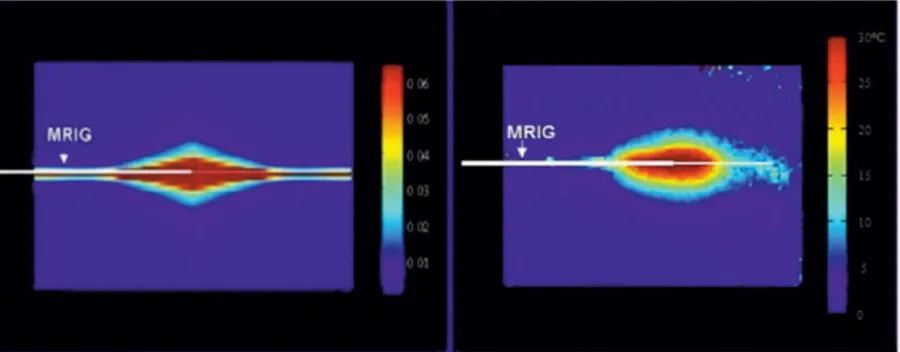
As calculated, the power loss along the MRIG increased as RF frequency increased. For a 1-m MRIG, at a frequency of 2.45 GHz, more than 80% of input power was lost, and, at 360 MHz half the power was lost. For the purpose of simultaneous MR imaging/RF heating/MR thermal map-ping, 180 MHz was chosen as the RF heating frequency with a loss of 36% input power. The simulated RF power distribution of the MRIG at this frequency is shown in Fig. 2a. The pattern of power distribution at this frequency was cylindrically symmetric, analogous to the geometry of ves-sels, and localized at the junction of the inner and outer conductors of the MRIG. This distribution fit the require-ment of intravascular local heating at the target vessel only.
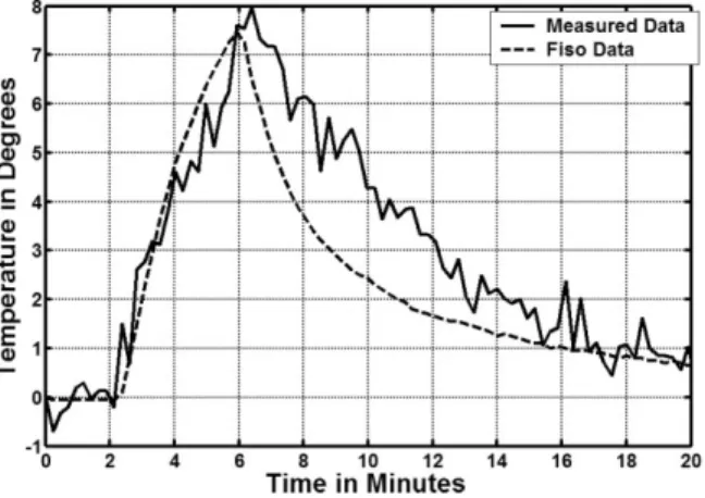
The in vitro study showed that the MR/RF system could simultaneously produce RF heating and MR imaging/MR thermal mapping using the same MRIG. The MR thermal mapping along the MRIG is shown in Fig. 2b. The pattern of simulated RF power distribution was comparable to that of in vitro MR thermal mapping. In the in vivo study, the target aorta was localized with axial and sagittal MR im-ages of the aorta (Fig. 3a and b). The target aortic wall was heated up to approximately 44°C from a baseline temper-ature of 37°C by operating the RF generator at 4 –5 W for about 4 min, and thermal mapping was obtained and reg-istered to the anatomic MR image of the aorta (Fig. 3c). To eliminate undesired temperature estimates, regions with an SNR of less than 10% of the maximum SNR of the anatomic images were excluded when generating the ther-mal maps. No significant magnetic field drift was noted in the references during the procedure. The temperature curve was obtained at the fiber-optic sensor location from the series of MR thermal maps using a 3⫻ 1 mask (0.6 ⫻ 0.2 mm), thus matching the sensing area of the indepen-dent temperature sensor. Figure 4 shows that the estimated temporal curve closely matched that of the actual
temper-ature curve measured using the Fiso thermometer with a SD error of 1.2°C.
DISCUSSION
Efficient transfer of therapeutic genes into a target vessel wall is critical for successful vascular gene therapy. Pri-marily, there are two ways to achieve efficient gene trans-fer. One way is to locally deliver genes, via a catheter-based approach, so that highly concentrated genes are delivered into only the target vessel wall without systemic toxicity. This requires an in vivo imaging method to pre-cisely monitor the distribution of the delivered genes within the target vessel wall (9). Another way is to use a method that will enhance gene delivery and expression. Previous in vitro studies have shown that heat can en-hance gene expression (10,11). The proposed mechanisms for this may include the fact that heating can fracture tissues, increase the permeability of the plasma membrane and cell metabolism, and increase the activity of heat-sensitive heat shock proteins (10,11).
Since the control of RF heating is critical to thermal enhancement of vascular gene therapy, a thermometry to monitor, and thereby control, the temperature change at
the vessel wall, is essential. To date, there are no efficient techniques available to monitor temperature increase at a vessel wall. MR imaging provides a potential tool to mon-itor temperature change in a large FOV using a surface coil. However, this method is limited for deep-seated, thin ves-sels, because the SNR is very low for these vessel walls. To solve this problem, in the current study we used the MRIG not only as an intravascular heating source to deliver RF energy to the target vessel, but also as an MR imaging receiver, combined with phase array coils, to provide MR imaging with high SNR of the vessel wall. This design enabled us to monitor RF temperature increases using MR thermal mapping. The SNR profile of the MRIG was com-parable to the pattern of simulated RF power distribution, which indicated the suitability of simultaneous perfor-mance of intravascular RF delivery and MR thermal map-ping using the same MRIG. However, as shown in Fig. 3c, parts of the thermal maps show negative values, which is attributable to phase variations around the MRIG, resulting from breathing and vessel pulsing. In the future, we will develop methods to correct for such undesired phase changes. In Fig. 4, the real temperature recorded by the Fiso thermometer was a little bit lower than the measured temperature by MR thermometer. The possible reasons for
FIG. 2. (Left) Mathematical simulation presents the pattern of RF power distribution of the 0.032-inch MR imaging guidewire (MRIG) (arrow) at 180 MHz. The power was normalized to 1-W input. (Right) In vitro MR thermal mapping on a gel phan-tom with 6-W RF power input. The MRIG was placed in the center of the phantom. The MR ther-mal mapping was obtained with SPGR, TR/TE/ FL⫽ 68/15/30, 256 ⫻ 256, 8 mm, and Nex ⫽ 1. The profiles of RF power distributions and MR thermal mapping were relatively comparable.
FIG. 3. The axial (a) and sagittal (b) MR images to localize the target aorta of the rabbit. The white arrows in (a) and (b) indi-cate the location of the fiber-optic sensor. A series of frames obtained from MR thermal mapping (c), which are overlapped on sag-ittal MR images.
this difference may include the change in the coefficients with temperature orientation and the length of the temper-ature sensor, which measured the average tempertemper-ature of the surrounding tissue and did not exactly align with the pixel in MR thermal mapping.
In the current study, we have designed and validated the concept of an “all-in-one” intravascular MR imaging/RF heating system, which integrates different functions of the MRIG-based endovascular interventional MR technique, including: (a) precise guidance of the gene delivery cath-eter to the target vessels (4,9); (b) prompt monitoring of gene transfer to the target vessel wall (1); and (c) simulta-neous delivery of RF thermal energy to enhance vascular gene transfection/expression and monitoring of the MRIG-mediated local RF heat at the target vessel wall using MR thermometry (2,3). This intravascular MR imaging/RF heating system with the all-in-one function of guiding/ enhancing/mapping should benefit MR-based vascular gene/drug therapy.
To monitor RF heat changes with MR thermal mapping, the precise localization of the target vessel is one of the critical factors that can significantly affect the performance of the MR/RF system. In our in vivo experimental setting, there was not only fat tissue surrounding the target vessel wall, but also two metal rings from the balloon. In clinical practice, the two metal rings are necessary to serve as markers for positioning the balloon under either X-ray imaging or MR imaging (9). Under MR imaging, we could use the signal void from the metal rings to precisely local-ize the fiber-optic sensor, which was positioned, side by side, onto the middle portion of the balloon. To obtain satisfactory SNR, we selected an MR image slice larger than the diameter of the balloon, while to avoid partial volume effects from fat surrounding the vessel wall we generated MR images with fat suppression to increase the sensitivity of the PRF method. In the current study, we
obtained the thermal mapping slice in a sagittal view, on which both the fiber-optic sensor and the mask for creating the temperature curve were localized exactly across the middle portion of the balloon. In addition, we used the high SNR MR images to precisely determine the exact position of the fiber-optic sensor and localization of the mask at the sensor on the thermal mapping images, which enables generation and comparison of both temperature curves obtained from MR thermal mapping and the fiber-optic sensor.
Future work needs to establish automatic control of the RF temperature at the target vessels and validate this MR imaging/RF heating system in a preclinical setting.
CONCLUSION
We demonstrate an MR imaging/RF heating system that provides two simultaneous functions of (a) creating local RF heat at the target vessel wall to enhance vascular gene transfer and (b) generating MR thermometry to simulta-neously monitor RF heating at the targets. This technique presents a potential tool for intravascular MR-based gene therapy.
ACKNOWLEDGMENTS
The authors thank Ms. Mary McAllister for her editorial assistance and. Ms. Carolyn Magee and Laurie Jean Pipi-tone for their technical support.
REFERENCES
1. Yang X, Atalar E, Li D, Serfaty J, Wang D, Kumar A, Cheng L. Magnetic resonance imaging permits in vivo monitoring of catheter-based vascu-lar gene delivery. Circulation 2001;104:1588 –1590.
2. Du X, Qiu B, Zhan X, Kolmakova A, Gao F, Hofmann LV, Cheng L, Chatterjee S, Yang X. Radiofrequency-enhanced vascular gene trans-duction using an intravascular MR imaging-guidewire as a heat vehicle. Radiology 2005, in press.
3. Qiu B, Yeung CJ, Du X, Atalar E, Yang X. Development of an intravas-cular heating source using an MR imaging-guidewire. J Magn Reson Imaging 2002;16:716 –720.
4. Omary R, Green J, Schirf B, Li Y, Finn J, Li D. Real-time magnetic resonance imaging-guided coronary catheterization in swine. Circula-tion 2003;107:2656 –2659.
5. Simon R, Whinnery J, Duzer V. Fields and wave in communication electronics. New York: Wiley, 1994.
6. Polk C, Postow E. Handbook of biological effects of electromagnetic fields. Boca Raton, FL: CRC Press, 1986.
7. Chung A, Hynynen K, Colucci V, Oshio K, Cline H, Jolesz F. Optimi-zation of spoiled gradient-echo phase imaging for in vivo localiOptimi-zation of a focused ultrasound beam. Magn Reson Med 1996;36:745–752. 8. Ishihara Y, Calderon A, Wantanabe H, Okamoto K, Suzuki Y, Kuroda K
Yutaka Suzuki Y. A precise and fast temperature mapping using water proton chemical shift. Magn Reson Med 1995;34:814 – 823.
9. Yang X. Imaging of vascular gene therapy. Radiology 2003;228:36 – 49. 10. Madio D, van-Gelderen P, DesPres D, Olson A, de-Zwart J, Fawcett T, Hobrook N, Mandel M, Moonen C. On the feasibility of MRI-guided focused ultrasound for local induction of gene expression. J Magn Reson Imaging 1998;8:101–104.
11. Takai T, Ohmori H. Enhancement of DNA transfection efficiency by heat treatment of cultured mammalian cells. Biochim Biophys Acta 1992;1129:161–165.
FIG. 4. The temporal temperature curve obtained by the measure-ments from MR thermal mapping (solid curve). The dotted curve indicates the actual temperature change recorded with the corre-sponding fiber-optic sensor. The temperature curve obtained from MR thermal mapping closely matches that of the actual temperature curve measured with the Fiso thermometer with a SD of 1.2°C.