www.advmat.de
Slit Tubes for Semisoft Pneumatic Actuators
Lee Belding, Bilge Baytekin, Hasan Tarik Baytekin, Philipp Rothemund, Mohit S. Verma,
Alex Nemiroski, Dan Sameoto, Bartosz A. Grzybowski, and George M. Whitesides*
DOI: 10.1002/adma.201704446
actuators produce a range of motions using a simple and flexible design (that is, patterns of slits in a tube fabricated from a flexible but nonextensible or com-pressible polymer), when actuated by pneumatic expansion of a “bladder” or “balloon” inside the region patterned with slits. The mechanics of this general type of system has been explored extensively by Bertoldi,[10] and our work combines our experiments and her analyses. Our work and hers differ substantially in the details of the devices used to demonstrate princi-ples of operation.
The design we use for SLiT actua-tors has a historical precedent in pleated pneumatic artificial muscles (pleated PAMs[11])—a subclass of McKibben[12]-like actuators—in which a number of pleats are formed along the direction of actuation, and the actuator expands by unfolding these pleats. These pleated PAMs, originally developed by Daerden et al.,[11] contract when pneumatic pressure is applied and form the basis for fiber-reinforced elastomeric actuators[10b,c,13] and fluid elastomeric actuators,[14] which are now being designed and optimized for soft robots. Martinez et al. implemented a similar strategy by fabricating an elastomeric soft actuator, where parallel slits were cut on a roll of paper and the paper was then embedded in a layer of elastomer.[15] Pneumatically pressurizing the center of the roll opens the slits, and expanded the struc-ture like a Japanese lantern. Overvelde et al. used a similar structure—by introducing a plastic braid around an elasto-meric tube—to amplify motion by exploiting snap-through instabilities.[16]
This article describes a new principle for designing soft or ‘semisoft’ pneu-matic actuators: SLiT (for SLit-in-Tube) actuators. Inflating an elastomeric balloon, when enclosed by an external shell (a material with higher Young’s modulus) containing slits of different directions and lengths, produces a variety of motions, including bending, twisting, contraction, and elongation. The requisite pressure for actuation depends on the length of the slits, and this dependence allows sequential actuation by controlling the applied pres-sure. Different actuators can also be controlled using external “sliders” that act as reprogrammable “on-off” switches. A pneumatic arm and a walker constructed from SLiT actuators demonstrate their ease of fabrication and the range of motions they can achieve.
Pneumatic Actuators
Mechanical devices—devices that can do mechanical work by extending, contracting, bending, and rotating—often require multiple actuators, each with a different design. Achieving complex motions, such as those needed for manipulation of objects[1] or locomotion,[2] becomes cumbersome because each component of a device has different requirements for its design, fabrication, control, and operation. Soft actuators[3] have simplified a number of kinds of tasks—manipulating soft, delicate objects,[4] compliant gripping of objects with com-plex or irregular shape,[5] manipulating of parts of the body,[6] and moving in confined spaces[7]—that were either difficult or impossible using hard components.[8] Soft mechanical devices have, of course, their own limitations, such as their load bearing capacity, the maximum number of actuation cycles they can withstand, and the inverse-kinematics problem for linear soft bodies.[9] Here, we demonstrate proofs-of-concept for a new class of actuators—SLiT (for SLit-in-Tube) actuators. These
Dr. L. Belding, P. Rothemund, Prof. M. S. Verma, Prof. A. Nemiroski, Prof. D. Sameoto, Prof. G. M. Whitesides
Department of Chemistry and Chemical Biology Harvard University
12 Oxford Street, Cambridge, MA 02138, USA E-mail: [email protected]
Prof. B. Baytekin,[+] Prof. H. T. Baytekin,[++] Prof. B. A. Grzybowski[+++]
Department of Chemical and Biological Engineering Northwestern University
2145 Sheridan Road, Evanston, IL 60208, USA P. Rothemund
School of Engineering and Applied Sciences Harvard University
29 Oxford St, Cambridge, MA 02138, USA
The ORCID identification number(s) for the author(s) of this article can be found under https://doi.org/10.1002/adma.201704446.
[+]Present Address: Chemistry Department, Bilkent University, Ankara
06800 Turkey
[++]Present Address: UNAM, Bilkent University, Ankara 06800 Turkey [+++]Present Address: Institute for Basic Science, Center for Soft and
Living Matter and Department of Chemistry, UNIST, Ulsan 44919, South Korea
Prof. G. M. Whitesides
Wyss Institute for Biologically Inspired Engineering Harvard University
60 Oxford Street, Cambridge, MA 02138, USA Prof. D. Sameoto
Department of Mechanical Engineering University of Alberta
9211-116 Street NW, Edmonton, Alberta T6G 1H9, Canada P. Rothemund, Prof. G. M. Whitesides
Kavli Institute for Bionano Science and Technology Harvard University
We used slits in plastic tubes to create braids (segmented enclosures) outside an elastomeric structure that, when expanded pneumatically, generated a range of motions. These motions were changed in amplitude and direction simply by changing characteristics of the slits (Figure 1).
Our design is similar to the work presented by Overvelde et al., with several fundamental differences. Initially, the braids used by Overvelde et al. are in a buckled state, and demon-strate motion in 1D (elongation), the magnitude of which is dependent on the ratio between the length of the braid and the length of the inner elastomeric tube. Our plastic tubes (in most situations) are initially unstrained (straight) and deform only after applying pressure. Furthermore, the motion of SLiT actuators is independent of the length of the inner elastomeric tube, and instead is determined by the location and orientation of the slits. By changing the angle, position, and periodicity of the slits, we also generate bending and twisting (as well as superposition of these motions) to enable movement in all 3Ds. We have also developed actuators with more sophisticated motions—four-way bending, a motion that combines rotation and elongation, and a motion that combines bending and rota-tion. We use different lengths of slits to control the timing of actuators in series, and sliders to permit or inhibit actuators to create reprogrammable systems. Two demonstrations show that SLiT actuators can easily be combined to generate different types of actuations: i) a pneumatic “hand” (or gripper) that is able to screw-in a light bulb, and ii) a walker.
To fabricate these systems, we wanted a model structure with appropriate mechanical characteristics: This model should be hollow, light weight and be fabricated with thin walls that are bendable but not stretchable (to provide flexibility and strength simultaneously), easily cut or slit, and resistant to tearing at the tips of the slits in expansion. Drawing from our experi-ence with Arthrobots,[17] we settled on thin polypropylene tubes (OD = 11 mm, wall thickness = 0.45 mm), which are inexpen-sive and readily available commercially (in very high quality and great reproducibility, as drinking straws). We built the actuators by slitting these tubes (by marking the slits using a marker, placing a metal rod within the tube for support, and then using a craft knife to cut the slits manually) and inserting an elasto-meric balloon (silicone tubing—OD 6.4 mm, wall thickness 0.79 mm—sealed on one end using an ethylene-vinyl-acetate-based thermoplastic adhesive) inside the plastic tube (Figure 1). Motion is produced by expansion of the tube on pressurization of the balloon; this pressurization deforms the tube in the direc-tions permitted by the modirec-tions (bending and twisting) of the slits (and the polymer strips they define); these slits are spaced periodically or aperiodically around the circumference of the tube and along the length of the tube. The distance between two adjacent slits defines the width of a braid (WB). We allowed the length of the slits (Ls1) to vary from 2.5 to 4.0 cm to ensure that only a fraction of the tube goes through a transformation during the pressurization. Figure 1C shows the design parameters that can be changed to achieve different types of motions; Figure S1 (Supporting Information) illustrates these designs and motions. (In addition, Figure S2 (Supporting Information) illustrates designs of slits that could be used to prevent shear connections and tearing fracture at the ends of slits.)[18] Depending on the design, the circumference is divided into 8–12 sections. When
pressurized, the elastomeric balloon expands with a nonlinear pressure–volume relation;[16] this expansion causes the braids (the area between slits) to bend outward, and the tube to expand in width and a contract in length.
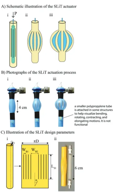
Figure 1. Operation and design of SLit-in-Tube (SLiT) actuators. A)
Sche-matic illustration of the operation of a SLiT actuator where i) the yellow outer cylinder is a polypropylene tube, the black vertical lines indicate slits, and the blue inner cylinder is the elastomeric balloon (sealed sili-cone tubing); ii) as the pressure in the elastomeric balloon is increased, it expands and causes the braids in the tube to bend; iii) when the bal-loon is fully inflated, the actuator reaches its maximum contraction. B) Photographs of the process illustrated in part (A); the polypropylene tube is blue and the elastomer is clear. The yellow tube protruding from the device has been affixed to the actuator to help depict motion. C) i) Illustra-tion of the design parameters used for controlling the posiIllustra-tion and orien-tation of slits in the tube. The rectangle is a schematic of a tube that has been cut open axially; black vertical lines mark the slits. D is the diameter of the tube, Ls1 is the length of the slits projected on to the vertical axis of
the tube, WB1 is the distance between slits, WB2 is the distance where no
slits are present, α is the angle of the slit relative to the vertical axis of the tube, which is 0° for a vertical slit. Various configurations of slit design are demonstrated in Figure S1 in the Supporting Information; ii) photograph of the components making up the actuators.
By changing the design of the slits, we can produce con-traction, elongation, bending, rotation, or combinations of these motions (Figure 2).
Contraction (Figure 2A) is accomplished using an actuator that consists of a tube with straight slits aligned parallel to the long axis of the tube. Pressurization of the actuator expands the bal-loon; this expansion applies pressure in the direction perpendic-ular to the length of the tube, and thus causes the braids to bend, and a contraction of the end-to-end length of the tube. The length
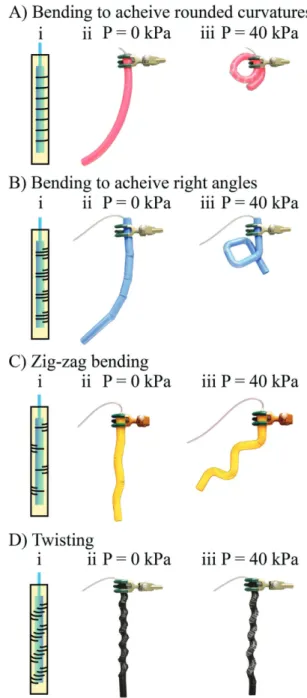
of the slits (LS1) dictates the total length of contraction (where longer LS1 gives larger contraction distances), and the pressure at which contraction begins and ends (higher actuation pressures are required for actuators with shorter slit lengths). (See Figure S3 (Supporting Information) for the dependence of contraction on length of slit.) We derived a simple kinematics model for the bending actuator that agrees well with the experimental data (see Supplementary Information for detailed analysis of the model, and comparison with experimental data). The actuator shows Figure 2. Actuators with vertical slits that produce localized contraction,
elongation, bending, or rotation, A) an actuator with eight slits that con-tracts, B) an actuator with eight slits, initially contracted by elastic rubber bands (red) that elongates upon inflation, C) an actuator with aperiodic vertical slits that bends. One quarter of its circumference was equally divided to two sections (by a single slit) and the rest was equally divided to eight sections, D) an actuator with eight vertical slits that rotates and contracts upon actuation.
Figure 3. Actuators with horizontal slits that produce different types of
motions, where i) is the schematic illustration of the actuator and slits, ii) is the photograph of unactuated system and iii) is the photograph of the actuated system pressurized to 40 kPa. Parts (A) and (B) show actua-tors that can curl with different curvatures. Part (C) shows an actuator that bends in a zig-zag manner. Part (D) shows an actuator that can twist and extend simultaneously.
the same change in length (i.e., contraction) when a 1.0 kg weight was attached to the bottom of the actuator (Figure S4, Supporting Information).
Elongation (Figure 2B) works on a basis similar to that of the contracting actuator, except that the braids are buckled in the unac-tuated state using two elastic rubber band on the sides of the tube. Inflating the balloon causes the elastomeric bands to expand, and the braids to return to their unbuckled, linear state (Figure S5, Supporting Information). In this way, elongation is determined only by the length of the slits, and does not rely on the length of the inner elastomeric tube to achieve an initially buckled state.
Bending (Figure 2C) relies on slits that are spaced apart nonuniformly. Since the width of the braid (distance between slits, WB) is different, each braid provides a different amount of resistance to bending (wider braids bend less because the same force is distributed over a larger area, and because the ratio of braid width to braid length is larger, and the braid stiffer). As a result, the tube expands asymmetrically upon inflation of the balloon—the section of the tube with thinner braids bends more, while the sec-tion with thicker braids bends less, and thus the whole structure bends toward the side of the tube with thinner braids. The width of the wider braid (WB2) determines the max-imum bending angle, which increases as WB2 increases (Figure S6 in the Supporting Infor-mation for the dependence of bending angle on width of the braid (WB2)).
Rotation (Figure 2D) is achieved by changing the angle of the slits with respect to the vertical axis of the tube (i.e., changing the angle of α), while maintaining the same slit length (LS) and distance between slits (WB) in Figure 2A. Inflation of the balloon forces the braids to bend along the axis of the slits, and causes a rotational motion that is a function of LS and the angle, α, of the slit relative to the axis of the tube (LS·sinα) (see Figure S7 in the Supporting Information for the dependence of torsion angle on the angle of the slits (α)).
Figure 3 demonstrates how SLiT actuators with horizontal slits (i.e., α = 90°) are capable of producing bending motions, and sharp changes in the curvature along the length of the tube. Here, the size of the elastomeric bal-loon matches the size of the tube (in all 3Ds). In a bending motion similar to that described previously, as the actuator is pressurized, and the balloon inflates, the horizontal braids bend; this bending in the braids forces the
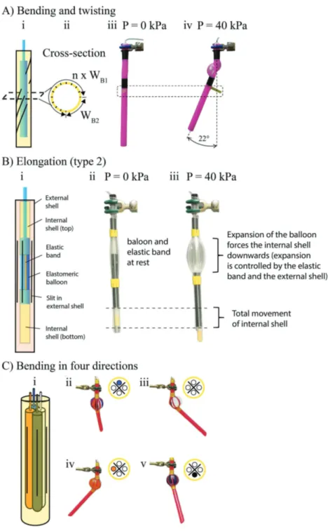
Figure 4. Actuators with sophisticated designs. A) An actuator that rotates and bends
simultaneously i) schematic illustration of the actuator, ii) cross-section of the actuator (n is the number of slits, other parameters are defined in Figure 1), iii) unpressurized actuator, iv) actuator pressurized to 40 kPa. The movement is enabled by asymmetrical nature of diagonal slits where n × Lp1 is 3/4th of tube circumference. The rotation is 90°
while the bending is 22° from the vertical axis. B) Elongation actuator with an external shell. The actuator consists of two segments of polypropylene tubing (the internal shell), a balloon, an elastomeric band connecting two parts of the internal shell, and an external tube restricting expansion of the balloon (external shell). ii) Photograph of the actuator in its unpressurized state. iii) Photograph of the actuator in its pressurized state (40 kPa). C) The four-way bending actuator. i) A schematic of an actuator capable of bending in four directions. The actuator consists of a single tube with four slits and four independently actuated balloons. ii–v) Photographs of the actuator when different balloons (as indicated by the filled circle in the cross-section schematic shown in the inset of each image) are pressurized.
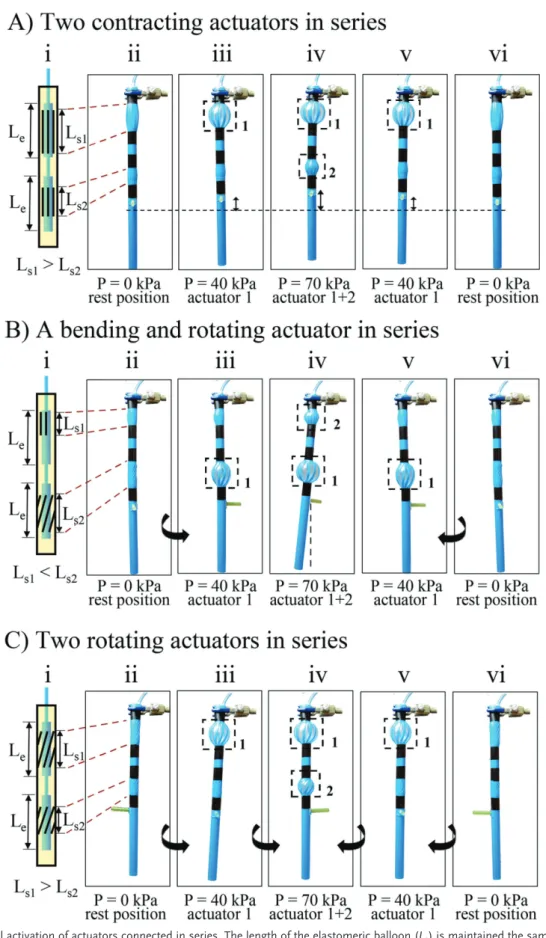
Figure 5. Sequential activation of actuators connected in series. The length of the elastomeric balloon (Le) is maintained the same for each segment
in all the actuators. A) Two contracting actuators in series. Slits of the top segment are 4 cm long while the ones in the bottom segment are 2.5 cm long. B) Bending and rotating actuators in series. The slit of bending segment is 2.5 cm long while the slit of rotation segment is 4 cm long. C) Two rotating actuators in series. Slits of the top segment are 4 cm long while the ones in the bottom segment are 2.5 cm long.
structure to bend in the nonslitted region. In this fashion, we are able to change the entire shape of the device; to curl up into a circle (Figure 3A), to create a (roughly) square shape (Figure 3B), to form a zig-zag pattern (Figure 3C), or twist about its axis (Figure 3D) (in a motion not unlike that of a screw driver).
We next demonstrated that the designs of slits can be com-bined to achieve complex motions. For example, to combine rotation and bending, we placed the slits diagonally around the circumference (for rotation) and leave an area without slits (for bending). Pressurization (40 kPa; 100 kPa = 1 atm) of the inner balloon results in simultaneous rotation and bending of the structure (Figure 4A).
Figure 4B shows an alternative expanding actuator that does not require prebuckled braids. This design uses two plastic tubes (placed concentrically) and one elastomeric bal-loon. The outer plastic tube has slits (and thus braids) that restrict the expansion of the balloon (which is shorter than the braids). The inner plastic tube (without any slits) has two segments and is attached to the upper and lower parts of the elastomeric balloon to act as a shaft. An elastic band holds the two segments of the inner plastic tube together (and returns them to their initial position). Upon pressurization, the bal-loon expands and moves the inner tube (and thus causes the visible extension of the device), while the external tube limits the expansion and enables directional motion by changing the design of the slit.
We also developed an actuator that can bend in four direc-tions (Figure 4C) by placing four balloons within the same tube. Each of the balloons can be inflated independently. The actuator thus has four degrees of freedom. Similar strategies to achieve bending have been used by us[19] and others [13b,20] (see the Supplementary Information for a schematic diagram of this four-directional actuator in Figure S5).
Using SLiT actuators, we implemented sequential actuation by changing the length of the slits (LS) and hence the pres-sure at which they actuate. When the width of the braid (WB, length between slits) is kept constant, the bending stiffness of a braid depends on its length (defined by the slit length, LS), with shorter braids being more resistant to applied pressure. Thus,
the critical pressure at which the actuator is activated changes with slit length. Figure 5 demonstrates that the actuators with longer slits (4 cm) respond at lower pressure (40 kPa) than the actuators with shorter slits (2.5 cm), which respond at higher pressure (70 kPa). This difference is a particularly important concept in actuation because it allows multiple motions to be achieved in a desired sequence by increasing the pressure from P1 to P2. Thus, multiple different actuators (of different type, motion, and physical location) can be activated at different times, using a single input (see the Supporting Information for sequential actuation with a load of 1 kg in Figure S6A,B).
Using short segments of tubing, we demonstrate how sliders—made from the same polypropylene material as the external shell of the actuators, but with a 1 mm larger diam-eter—are able to permit or inhibit actuation of individual com-ponents. The sliders, shown in Figure 6, fit tightly around the external shell and remain in place during inflation of the bal-loon. When a slider rests over an area with slits, it remains dormant under pressurization, while the slitted areas not covered by a slider activate as usual. Using this principle, we demonstrate how all combinations of three different actuators, in series, can be achieved, in a single device (Figure S10, Sup-porting Information).
To demonstrate the potential for utility and robustness of SLiT actuators, we constructed a pneumatic gripper by con-necting five actuators, as demonstrated in Figure 7. In this design, a rotating and an elongating actuator were connected in sequence (to allow two independent twisting and extending motions) and three bending actuators were attached to a disk at equal spacing (to enable gripping). The completed device, using only two pressure inputs, is able to perform a fairly complex task: gripping, placing, and screwing in a light bulb. (The ini-tial alignment above the socket was performed manually). (See Supplementary Information for operation of the device in Video S1, Supporting Information.)
We also assembled a walker to demonstrate locomotion using SLiT actuators. The walker consists of 12 rotating actua-tors (Figure 8). The actuaactua-tors are assembled together using a 2D frame that is put together using polypropylene tubes. The
Figure 6. Reprogrammable sliders. A SLiT actuator consisting of a rotating actuator, a bending actuator, and a contracting actuator, in series, with two
sliders. A) Schematic of the series of actuators with sliders inhibiting the rotating and contracting actuators (left). Photograph of the series of actuators bending in one direction (right). B) Schematic of the series of actuators with sliders inhibiting the contracting actuator (left). Photograph of the series of actuators which has rotated by 180°, and is now bending in the opposite direction (right). C) Schematic of the series of actuators where the sliders are not inhibiting any of the actuators (left). Photograph of the series of actuators which has all of the actuators activated (right).
feet of the walker consist of a rotating actuator with two small wooden sticks added to the surface of the actuator, positioned to elevate the walker and introduce friction when actuators are pressurized. To enable locomotion six actuators are arranged to function as a tripod gait,[17] which is the same walking strategy used by six-legged insects, such as ants.[21] Two orthogonally oriented tripod gaits allow us to move the walker forward, back-ward, left, and right (see Video S2, Supporting Information). The walker is very light weight (0.5 lbs), easily assembled, and requires no molding, 3D printing, or programming in its assembly.
We have demonstrated, using a model system, a new class of actuators (SLiT actuators) that produce a range of motions using a flexible strategy for design and fabrication. These actuators,
in principle, can be applied to any system made with material fabricated from a flexible but non-extensible or compressible polymer. Changing the position and orientation of slits in SLiT actuators achieves a variety of motions: elongation, contraction, bending, and rotation. These slit designs can also be combined in several ways to further increase their versatility: superimposi-tion (to achieve a complex mosuperimposi-tion that is the sum of individual designs, e.g., simultaneous bending and twisting), combinations in parallel (to increase the range of motion, e.g., four-way bending), and combinations in series (to actuate different actua-tors sequentially, e.g., to achieve bending, followed by twisting). Slit actuators can also be paired with sliders, which act as repro-grammable “on-off” switches for further control of the system. Thus, SLiT actuators allow the programming of many complex Figure 7. A robotic arm made using SLiT actuators. A) Schematic diagram of the arm where A1 is a rotating actuator, with pressure P1, A2 is an
elon-gation actuator, also with P1, and A3–A5 are bending actuators, with pressure P2, (B–M) show the operation of the arm while screwing in a light bulb
motions simply by slitting tubes. The fiber-reinforced actuators (FRAs) developed by Connolly et al.[10b,c] have demonstrated manual and automatic programming of biomimetic motions— extension, contraction, twisting, and bending. In these systems, the fibers direct motion by inhibiting radial expansion and allowing axial expansion (or inhibiting axial expansion to pro-duce radial expansion), whereas SLiT actuators harness radial expansion to achieve motion, which includes axial expansion (or contraction). For example, the twisting motion in FRAs is achieved without the radial expansion associated with rotating SLiT actuators. The differences between these two systems are most apparent for the bending actuator; FRAs bend by using two different elastomers, while SLiT actuators can bend by simply changing the slit design. SLiT actuators differ from these FRAs (and our earlier paper-based composites[4a,7,22]) in six additional characteristics: i) The fabrication of SLiT actua-tors is simpler and faster than that of FRAs. It simply involves cutting plastic tubes and gluing elastomeric balloons, in places where FRAs involve designing a mold, 3D-printing the mold, pouring and curing elastomers, and then wrapping fibers around the elastomers. ii) SLiT actuators can perform super-imposed motions in the same segment of the actuator (e.g., Figure 4A shows simultaneous twisting and bending) while, at present, FRAs need to use different segments (similar to joints in a biological digit) to provide each different type of motion.
iii) SLiT actuators can achieve bending motion more easily (by changing the spacing between the vertical slits or by using horizontal slits) than FRAs; some FRAs require the use of two different elastomers, which need to be cured separately. iv) A single segment of the SLiT actuator can achieve four (or more, depending on the number of internal balloons and pneumatic inputs) directions of bending (Figure 4C); each segment of a FRA can bend only in one direction. v) SLiT actuators are not completely soft (because they use a stiff but flexible plastic com-ponent and an elastic comcom-ponent), whereas FRAs are mostly soft (except for ends where vented screws are embedded). vi) the critical pressure for actuation of SLiT actuators primarily depends on the length of the braid formed in the material, whereas the critical pressure for FRAs depends mainly on the angle of the fibers.
Because SLiT actuators rely on expansion of the inner elastomeric tube for motion, there is always a radial expan-sion and an axial contraction. This reliance on expanexpan-sion is the basis for control with external sliders, but may not be desirable in some circumstances. Because FRAs do not func-tion by harnessing radial expansion, they do not have this limitation, but also cannot be controlled with reprogrammable sliders. In SLiT actuators, the concentration of stress at the edges of the slits can lead to tearing (which can be resolved, to some extent, by using the alternative slit designs discussed in Figure 8. Walker consisting of 12 rotating actuators, arranged into two tripod gates, enables motion in two directions; two sets of three actuators (one
tripod gate) allow forward motion and another set of three actuators facilitates sideways motion. A) A schematic illustration (insets show photographs of one of the actuators) of the actuator with two pins underneath forming its legs. B) The schematics of the network of the actuators which formed the walker. For the forward actuators, one set of three actuators (labelled P1) is synchronized by a common pressure inlet, and a second set of actuators
(labelled P2) is controlled by another common pressure inlet. C,D) The photographs of the walker moving forward (see Video S2, Supporting
Informa-tion), which is accomplished by alternating the actuation of P1 and P2. Note that only horizontal actuators (red ones) have legs. The blue actuators are
the Supporting Information). FRAs do not suffer from tearing in this way.
The simplicity and ease of fabrication, the range of motions, and the extent of control associated with SLiT actuators, as well as the possibility for variation in materials, make them excel-lent candidates for complex, yet disposable, devices. Using dif-ferent materials and higher activation pressures (>100 psi), the scope and utility of SLiT-based devices can likely be expanded further.
Experimental Section
The polypropylene tubing used for the external shell, and the sliders, is Monsterstraw brand (0.5″ × 10.5″). The silicone tubing used as the elastomeric balloon was obtained from New Age Industries (OD 1/4″, wall thickness 1/32″). The ethylene-vinyl-acetate-based thermoplastic adhesive was FPC Best Stik Glue Sticks brand (7/16″ x 4″).
Supporting Information
Supporting Information is available from the Wiley Online Library or from the author.
Acknowledgements
Research on different mechanisms of actuation is funded by the Department of Energy, Office of Basic Energy Sciences, Division of Materials Science and Engineering under award # ER45852. L.B. is funded by a Natural Sciences and Engineering Research Council of Canada (NSERC) postdoctoral fellowship from the Government of Canada. B.B. and H.T.B. acknowledge Northwestern University (2014). M.S.V. is funded by a Banting postdoctoral fellowship from the Government of Canada. P.R. acknowledges support from the Harvard MRSEC supported by NSF (DMR 14-20570). D.S. acknowledges funding support from the NSERC.
Conflict of Interest
The authors declare no conflict of interest.
Keywords
external shells, pneumatic actuators, pneumatic artificial muscles, semisoft, sequential actuation, soft robotics
Received: August 7, 2017 Revised: October 30, 2017 Published online: January 15, 2018
[1] M. R. Cutkosky, Robotic Grasping and Fine Manipulation, Vol. 6, Springer Science & Business Media, Springer, Boston, MA 2012. [2] C. Wright, A. Johnson, A. Peck, Z. McCord, A. Naaktgeboren,
P. Gianfortoni, M. Gonzalez-Rivero, R. Hatton, H. Choset, in Proc.
IEEE Int. Conf. IROS, IEEE, San Diego, CA, USA 2007, pp. 2609–2614.
[3] a) H. Rodrigue, W. Wang, M.-W. Han, Y.-J. Quan, S.-H. Ahn, Sens.
Actuators, A 2016, 237, 96; b) X. Gong, K. Yang, J. Xie, Y. Wang,
P. Kulkarni, A. S. Hobbs, A. D. Mazzeo, Adv. Mater. 2016, 28, 7533;
c) T. J. Noah, L. Mario, W. Nastasia, W. Gu-Yeon, J. W. Robert,
Smart Mater. Struct. 2016, 25, 055033; d) G. Wei, W. Jia, Y. Yanlei, Chin. Phys. B 2016, 25, 096103.
[4] a) F. Ilievski, A. D. Mazzeo, R. F. Shepherd, X. Chen, G. M. Whitesides, Angew. Chem. 2011, 123, 1765; Angew. Chem.,
Int. Ed. Engl. 2011, 50, 1890; b) K. C. Galloway, K. P. Becker,
B. Phillips, J. Kirby, S. Licht, D. Tchernov, R. J. Wood, D. F. Gruber,
Soft Rob. 2016, 3, 23.
[5] E. Brown, N. Rodenberg, J. Amend, A. Mozeika, E. Steltz, M. R. Zakin, H. Lipson, H. M. Jaeger, Proc. Natl. Acad. Sci. USA
2010, 107, 18809.
[6] a) P. Polygerinos, S. Lyne, Z. Wang, L. F. Nicolini, B. Mosadegh, G. M. Whitesides, C. J. Walsh, Proc. IEEE Int. Conf. IROS, IEEE, Tokyo, Japan 2013, pp. 1512–1517; b) H. Zhao, K. O’Brien, S. Li, R. F. Shepherd, Sci. Rob. 2016, 1, eaai7529; c) E. T. Roche, M. A. Horvath, I. Wamala, A. Alazmani, S.-E. Song, W. Whyte, Z. Machaidze, C. J. Payne, J. C. Weaver, G. Fishbein, J. Kuebler, N. V. Vasilyev, D. J. Mooney, F. A. Pigula, C. J. Walsh, Sci. Transl. Med. 2017, 9, eaai9084. [7] R. F. Shepherd, F. Ilievski, W. Choi, S. A. Morin, A. A. Stokes,
A. D. Mazzeo, X. Chen, M. Wang, G. M. Whitesides, Proc. Natl.
Acad. Sci. USA 2011, 108, 20400.
[8] a) D. Rus, M. T. Tolley, Nature 2015, 521, 467; b) C. Majidi, Soft Rob.
2014, 1, 5.
[9] a) F. Renda, M. Giorelli, M. Calisti, M. Cianchetti, C. Laschi, IEEE
Trans. Rob. 2014, 30, 1109; b) R. J. Webster, B. A. Jones, Int. J. Rob. Res. 2010, 29, 1661.
[10] a) J. T. Overvelde, T. Kloek, J. D’Haen J, K. Bertoldi, Proc. Natl.
Acad. Sci. USA. 2015, 112, 10863; b) F. Connolly, P. Polygerinos,
C. J. Walsh, K. Bertoldi, Soft Rob. 2015, 2, 26; c) F. Connolly, C. J. Walsh, K. Bertoldi, Proc. Natl. Acad. Sci. USA 2017, 114, 51.
[11] F. Daerden, D. Lefeber, Eur. J. Mech. Environ. Eng. 2002, 47, 11.
[12] a) V. L. Nickel, J. Perry, A. L. Garrett, J. Bone Jt. Surg. 1963, 45, 933; b) M. M. Gavrilovic´, M. R. Maric´, J. Med. Biol. Eng. 1969, 7, 77; c) C. S. Kothera, M. Philen, B. Tondu, J. Intell. Mater. Syst. Struct.
2012, 23, 225.
[13] a) G. Singh, G. Krishnan, in Proc. IEEE Int. Conf. IROS, IEEE, Hamburg, Germany 2015, 1738–1743; b) G. Krishnan, J. Bishop-Moser, C. Kim, S. Kota, J. Mech. Rob. 2015, 7, 041014; c) J. Bishop-Moser, S. Kota, IEEE Trans. Rob. 2015, 31, 536; d) Z. Wang, P. Polygerinos, J. T. B. Overvelde, K. C. Galloway, K. Bertoldi, C. J. Walsh, IEEE/ASME Trans. Mechatronics 2017, 22, 717.
[14] a) B. C. Mac Murray, X. An, S. S. Robinson, I. M. van Meerbeek, K. W. O’Brien, H. Zhao, R. F. Shepherd, Adv. Mater. 2015, 27, 6334; b) J. C. Yeo, H. K. Yap, W. Xi, Z. Wang, C.-H. Yeow, C. T. Lim, Adv.
Mater. Tech. 2016, 1, 1600018.
[15] R. V. Martinez, C. R. Fish, X. Chen, G. M. Whitesides, Adv. Funct.
Mater. 2012, 22, 1376.
[16] J. T. Overvelde, T. Kloek, J. J. D’haen, K. Bertoldi, Proc. Natl. Acad.
Sci. USA 2015, 112, 10863.
[17] A. Nemiroski, Y. Y. Shevchenko, A. A. Stokes, B. Unal, A. Ainla, S. Albert, G. Compton, E. MacDonald, Y. Schwab, C. Zellhofer, G. M. Whitesides, Soft Rob. 2017, 4, 183.
[18] C. E. Inglis, Trans. Inst. Nav. Architects 1913, 55, 219.
[19] a) R. V. Martinez, J. L. Branch, C. R. Fish, L. Jin, R. F. Shepherd, R. M. Nunes, Z. Suo, G. M. Whitesides, Adv. Mater. 2013, 25, 205; b) S. A. Morin, Y. Shevchenko, J. Lessing, S. W. Kwok, R. F. Shepherd, A. A. Stokes, G. M. Whitesides, Adv. Mater. 2014,
26, 5991.
[20] a) A. D. Marchese, R. K. Katzschmann, D. Rus, Soft Rob. 2015, 2, 7; b) A. D. Marchese, C. D. Onal, D. Rus, Soft Rob. 2014, 1, 75; c) A. Jusufi, D. M. Vogt, R. J. Wood, G. V. Lauder, Soft Rob. 2017.
[21] C. Zollikofer, J. Exp. Biol. 1994, 192, 107.
[22] a) B. Mosadegh, P. Polygerinos, C. Keplinger, S. Wennstedt, R. F. Shepherd, U. Gupta, J. Shim, K. Bertoldi, C. J. Walsh, G. M. Whitesides, Adv. Funct. Mater. 2014, 24, 2163; b) D. Yang,
B. Mosadegh, A. Ainla, B. Lee, F. Khashai, Z. Suo, K. Bertoldi, G. M. Whitesides, Adv. Mater. 2015, 27, 6323; c) D. Yang, M. S. Verma, E. Lossner, D. Stothers, G. M. Whitesides, Adv. Mater.