179
12
A Generic Multiview Rendering
Engine Architecture
M. Adil Yalçın
Tolga Çapın
Department of Computer Engineering, Bilkent University
12.1 Introduction
Conventional monitors render a single image, which is generally observed by the two eyes simultaneously. Yet, the eyes observe the world from slightly different positions and form different images. This separation between the eyes provides an important depth cue in the real world. Multiview rendering aims to exploit this fundamental feature of our vision system for enhanced 3D rendering.
Technologies that allow us to send different images to the two eyes have been around for years, but it is only now that they can reach the consumer level with higher usability [Bowman et al. 2004]. The existing technologies vary among the different types of 3D displays, and they include shutter glasses, binoc-ular head-mounted displays, and the more recent and popbinoc-ular autostereoscopic displays that require no special glasses.
Recent techniques for multiview rendering differ in terms of visual character-istics, fidelity, and hardware requirements. Notably, multiview rendering engines should be able to support more than two simultaneous views, following recent 3D display technologies that can mix a higher number of simultaneous views than traditional stereo view [Dodgson 2005].
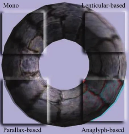
Currently, many available multiview applications are configured for the ste-reo-view case, and the routines that manage stereo rendering are generally im-plemented as low-level features targeted toward specific APIs and displays. We present a higher-level multiview rendering engine architecture that is generic, robust, and easily configurable for various 3D display platforms, as illustrated in
Figure 12.1. A torus rendered for different basic 3Ddisplay platforms.
Figure 12.1. The architecture simplifies the use of multiview components of a rendering engine and it solves the problems of rendering separate views and merging them for the target display. It also includes support for multiview ren-dering optimization techniques, such as view-specific level-of-detail systems and pipeline modifications. Additional discussions include insights on further exten-sions, design guidelines, and other possible uses of the presented architecture.
Most of the discussions, terminologies, and guidelines in this chapter follow OpenGL conventions. The implementation of the architecture is included in the OpenREng library,1 an open-source rendering engine based on modern desktop
and mobile OpenGL specifications with multiview rendering support, and the sample applications are built using this library.
12.2 Analyzing Multiview Displays
At its core, rendering for 3D displays aims to generate separate images (views) for separate eyes. All types of 3D displays, summarized below, create the illusion of 3D space based on multiplexing the different images for each eye, whether it be temporally, spatially, or in color. It is a challenge to support all types of dis-plays transparently to application implementations in a way that hides the details of the low-level resource management required for multiview rendering.
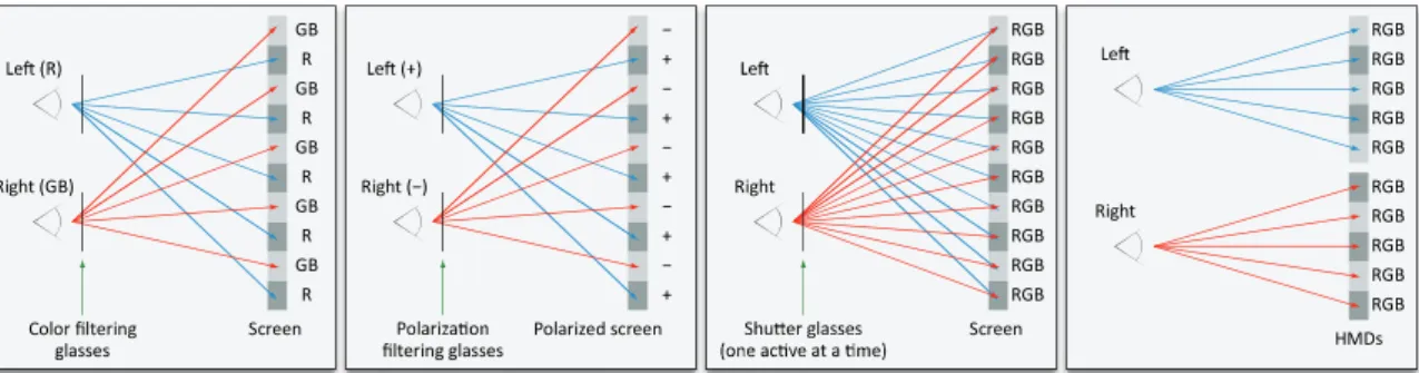
Displays that require wearing special eyeglasses can be subdivided into the following categories (as also shown in Figure 12.2):
1 See http://openreng.sourceforge.net/. Mono Parallax-based Lenticular-based Anaglyph-based
12.2 Analyzing Multiview Displays 181
Figure 12.2. Stereo rendering techniques that require wearing glasses. From left to right, anaglyph glasses, polarized glasses, shutter glasses, and head-mounted displays.
■ Anaglyph glasses. These are based on multiplexing color channels. The two views are filtered with different colors and then superimposed to achieve the final image.
■ Head-mounted displays (HMDs). These are based on displaying both views synchronously to separate display surfaces, typically as miniaturized LCD, organic light-emitting diode (OLED), or CRT displays.
■ Shutter glasses. These are based on temporal multiplexing of the two views. These glasses work by alternatively closing the left or right eye in sync with the refresh rate of the display, and the display alternately displays a different view for each eye.
■ Polarized glasses. With passive and active variants, these glasses are based on presenting and superimposing the two views onto the same screen. The viewer wears a special type of eyeglasses that contain filters in different ori-entations.
While these displays require special hardware, another type of 3D display, called an autostereoscopic display, creates the 3D effect without any special eye-glasses. Autostereoscopic displays operate by emitting a different image toward each eye of the viewer to create the binocular effect. This is achieved by aligning an optical element on the surface of the screen (normally an LCD or OLED) to redirect light rays for each eye. A composite image that superimposes the two views is rendered by the display subpixels, but only the correct view is directed to the corresponding eye.
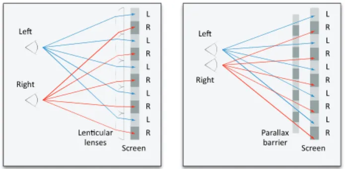
There are two common types of optical filter, a lenticular sheet and a parallax barrier. A lenticular sheet consists of small lenses having a special shape that re-fract the light in different directions. A parallax barrier is essentially a mask with
GB R GB R GB R GB R GB R Right (GB) Color filtering glasses Screen RGB RGB RGB RGB RGB RGB RGB RGB RGB RGB Right Screen − + − + − + − + − + Right (−) filtering glasses Polarized screen RGB RGB RGB RGB RGB RGB RGB RGB RGB RGB Right HMDs
Figure 12.3. Autostereoscopic displays: a lenticular sheet (left) and a parallax barrier (right).
openings that allow light to pass through only in certain directions. These two technologies are illustrated in Figure 12.3. In both cases, the intensity of the light rays passing through the filter changes as a function of the viewing angle, as if the light is directionally projected. The pixels for both eyes are combined in a single rendered image, but each eye sees the array of display pixels from a differ-ent angle and thus sees only a fraction of the pixels, those precisely conveying the correct left or right view.
The number of views supported by autostereoscopic displays varies. The common case is two-view, which is generally called view or stereo-rendering. Yet, some autostereoscopic 3D displays can render 4, 8, or 16 or more views simultaneously. This allows the user to move his head side to side and ob-serve the 3D content from a greater number of viewpoints. Another basic varia-ble is the size of the display. Three-dimensional TVs, desktop LCD displays, and even mobile devices with multiview support are becoming popular and accessible to the mass market.
As a result, it is a challenge to build applications that run on these different types of devices and 3D displays in a transparent way. There is a need for a mul-tiview rendering architecture that hides the details of multiplexing and displaying processes for each type of display.
12.3 The Architecture
The architecture we present consists of the following:
■ An extensible multiview camera abstraction.
■ An extensible multiview compositor abstraction.
L R L R L R L R L R Screen L R L R L R L R L R Right Parallax barrier lenses Screen Right
12.3 The Architect ■ A r ■ R ■ L T the m displ on th view pictu grap it on Brie mult Figu M buffe of th disti os. A Figu confi and o ture A configurab rendering resu Rendering pip Level-of-deta To be able to multiview sys lay surfaces. he screen, ev wport, as show ure multiview phical user int nly a single ti fly, with this tiview conten ure 12.5.
Multiview ren fer, and a mult hese compone nct set of fea At render tim ure 12.4. The igurations: ana on-target (stenc ble multiview ults. peline modifi ail implement o support both stem architec This further ven with diffe wn in Figure w regions to y terface (GUI) me after the approach, yo nt to be rende ndering is ena tiview compo ents are config atures, the sys me, the multiv
same scene re aglyph using c ciling), on-targ w buffer that ications to sup tations for mu h single-view cture is integr allows multi erent multivie 12.4. With t your screen, o ) elements ov multiview co ou have contr ered. An over abled by attac ositor to a vie gurable on th stem can be ad view renderin endered to diff color-mode (bo get-wiggle, and t holds inter pport multivie ultiview rende w and multivi rated into a v iview renderi ew configura this approach or you can sh ver multiview ontent is merg
rol over where rview of our ching a multiv ewport in a re heir own and p
djusted to fit ng pipeline is ferent viewpor ottom-left), pa d on-target-sep rmediate view ew rendering ering. iew rendering viewport abst ing in multip ations for eac h, you can ad
how your sin w 3D content b
ged into the f e and how yo r architecture view camera, ender window provide abstra into many ta s activated if rts with differe arallax using b arated. w-dependent . g seamlessly, traction over le viewports ch multiview d picture-in-gle-view 2D by rendering frame buffer. ou want your is shown in a multiview w. Since most action over a arget scenari-the attached ent multiview both off-target 183
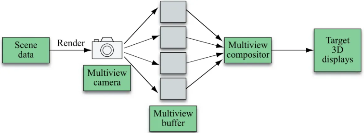
Figure 12.5. Overview of the multiview rendering architecture.
multiview components support the same number of views. As shown in Fig-ure 12.5, the scene is first rendered multiple times after activating a specific cam-era view and a specific view buffer target. This gencam-erates the rendering content to be used by the attached multiview compositor, which outputs its result to the re-gion of the rendered viewport. The last step is performed by the operating sys-tem, which swaps the final frame buffer holding the multiview content to be shown on the target displays.
The sample code provided in Listing 12.1 can add full support for anaglyph-based stereo-view rendering using our architecture without any other modifica-tions to the application code.
CameraStereoView& camera(CameraStereoView::create(*camNode));
// Set standard parameters.
// (aspect ratio, far-near dist., field-of-view, etc.)
camera.setEyeSeparation(0.3); // stereo-specific camera.setFocalDistance(25.0); // stereo-specific MVBuffer_Cfg mvbParams; mvbParams.viewCount = 2; mvbParams.type = MVBufferType_Offtarget; mvbParams.offtarget.colorFormat = ImageFormat_RGBA; mvbParams.offtarget.sharedDepthStencilTargets = true; mvbParams.offtarget.sharedFrameBuffer = true; Scene data Target 3D displays Multiview camera Multiview buffer Multiview compositor Render
12.4 The Multiview Camera 185
// Attach the components to viewport.
RSys.getViewport(0)->mCamera = &camera;
RSys.getViewport(0)->attachMVCompositor(new MVC_Anaglyph);
RSys.getViewport(0)->attachMVBuffer(new MultiViewBuffer, mvbParams);
Listing 12.1. Setting up a basic multiview rendering pipeline in an application.
12.4 The Multiview Camera
Multiview rendering requires each of the views to be rendered with view offset parameters, so that the eyes can receive the correct 3D images. To ease the con-trol of cameras in multiview configurations, our architecture provides a mul-tiview camera concept that is integrated into our basic mulmul-tiview rendering pipeline.
To be able to easily manipulate cameras within a generic multiview architec-ture, we define a single interface, the multiview camera. This interface allows for specialization of different configurations through class inheritance. Implementa-tions can integrate most of the multiview-specific functionality (e.g., activating a specific view) in a generic camera class, and single-view cameras can therefore be treated as simple multiview cameras.
As usual, the camera object is used to identify view and projection transfor-mation matrices that are applied to 3D mesh vertices. The view matrix depends on both the camera position and the multiview camera parameters that offset the view position from a reference camera transformation. The same approach ap-plies to the projection matrix—both basic intrinsic parameters (such as field of view, near and far clip plane distances, and aspect ratio) and multiview configu-ration parameters (such as focal length) can affect the final result.
In our design, a single multiview camera object aims to reflect a group of perspective-projection cameras. Each view is rendered using perspective projec-tion, which implies that the multiview camera has the properties of a perspective camera and can thus inherit from a perspective camera component, as shown in Listing 12.2. Intuitively, in multiview configurations, one wants to be able to control a single camera object that would internally calculate all view-specific parameters with respect to the base camera position and orientation. The view-specific perspective projection and view transformation are generated using an active view number, and this active view number needs to be automatically man-aged by the main renderer. Internal camera parameters are specified by extending the multiview camera interface and defining the required parameters that affect the view and projection matrix setup.
Also, each specific multiview camera implementation can define a single bounding volume to be used for one-time object culling over all views. The actu-al geometry covered inside a multiview volume is likely to be nonconvex, which can make precise intersection tests with the scene bounding volumes computa-tionally less efficient. To set a single, shared culling frustum for a multiview camera, a larger frustum that covers the multiview volume needs to be set up. The corners of a suitable approximation for an extended multiview culling frus-tum can be composed from the outermost corners of each view-specific frusfrus-tum. // Base camera interface provides basic multiview operations.
class Camera {
public:
// Get/set aspect ratio, near-far distance, field of view, etc. virtual uchar getViewCount() const; // returns 1 as default virtual void setActiveView(uchar viewIndex); // default no-op virtual const Matrix4& getViewMatrix() const;
const Matrix4& getProjectionMatrix() const;
const BoundingVolume& getFrustum() const;
protected:
mutable Matrix4 mProjMatrix_Cache;
mutable BoundingVolume mFrustum_Cache;
bool mProjMatrixMatrix_dirty, mFrustum_dirty;
virtual void updateProjMatrix() const = 0;
virtual void updateFrustum() const = 0; };
class CameraPerspective : public Camera {
... };
class CameraMultiView : public CameraPerspective {
public:
12.4 The Multiview Camera 187
void setActiveView(size_t viewIndex);
protected:
uchar mActiveView; };
class CameraStereoView : public CameraMultiView {
public:
// Set/get focal distance and eye separation. const Matrix4& getViewMatrix() const;
protected:
float mFocalDistance, mEyeSeparation;
void updateProjectionMatrix() const; };
Listing 12.2. Projection and view matrix management for stereo rendering.
The remainder of this section focuses on the special case of stereo cameras and describes the basic parameters that can allow easy and intuitive manipulation of the camera matrices. The concepts described in this section can be extended to multiview configurations that require more views.
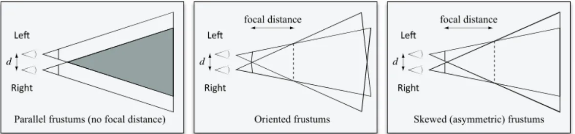
As shown in Figure 12.6, different approaches can be applied when creating stereo image pairs. In the figure, d denotes the separation between the eyes. Par-allel and oriented frustums use the basic symmetrical perspective projection setup for each view and offset the individual camera positions (and the camera orienta-tions, in the oriented frustum case). The skewed frustum approach modifies the perspective projection matrix instead of updating the camera orientation, so the two image planes are parallel to the zero-parallax plane.
The camera view position offset depends on the right direction vector of the base multiview camera and the d parameter. If the base camera is assumed to be in the middle of the individual view points, the offset distance is simply d 2 for each view. To generate skewed frustum projection pairs, assuming that the frus-tum can be specified with left-right, bottom-top, and near-far values, as is done
Figure 12.6. Basic approaches for setting up stereo camera projection frustum pairs.
for the OpenGL function glFrustum(), only the left and right values need to be
modified. The offset Δx for these values can be calculated using the formula Δ 2 dn x f ,
where n is the distance to the near plane, and f is the focal distance. Note that the projection skew offset Δx is added for the right camera and subtracted for the left camera.
Figure 12.7 shows a simple diagram that can be used to derive the relation-ship among the angle shift s, the eye separation d, half field-of-view angle , and the focal distance f. By using trigonometric relationships and the fact that lines intersect at the point p in the figure, the following equation can be derived:
2 2 2 1 tan tan 2tan 1 tan d θ s f s θ .As expected, a smaller angle shift s results in a larger focal distance, and the eye separation parameter d affects the focal distance linearly.
Figure 12.7. Derivation of the relationship between the angle shift s, the eye separation d, and the focal distance f.
Right d Right d Right d
Parallel frustums (no focal distance) Oriented frustums Skewed (asymmetric) frustums focal distance focal distance z x 2 d 2 d − p f θ s− θ s
12.5 The Multiview Buffer 189
12.5 The Multiview Buffer
Multiview rendering requires rendering separate views to distinct targets so that they can be mixed as required. The multiview buffer concept in this architecture aims to encapsulate important properties of the render targets that can be used in multiview pipelines.
The instances of multiview buffers are created by the application and at-tached to the viewports using multiview buffer configuration parameters. These parameters are designed to allow easy high-level configuration of internal re-sources (such as textures, render buffers, and frame buffers) that will be created. Although the multiview buffer concept is not designed for extensibility through class inheritance, the parameters can provide the required robustness to the appli-cation developer and can be extended by updating this single interface when re-quired.
After analyzing possible multiview configurations, we have observed that there are two basic types of multiview buffers:
■ On-target buffers for which we render to the viewport’s render target directly.
■ Off-target buffers that create and manage their own resources as render targets.
An on-target multiview buffer uses the attached viewport’s render surface instead of creating any new (offscreen) surfaces. A final compositing phase may not be needed when an on-target multiview buffer is used because the multiview render-ing output is stored in a srender-ingle surface. The renderrender-ing pipeline can still be spe-cialized for per-view operations using the multiview compositor attachments. For example, to achieve on-target anaglyph-based rendering, an attached compositor can select per-view color write modes, in turn separating the color channels of each view, or a compositor can select different rendering regions on the same surface. Also, OpenGL quad-buffer stereo mode can be automatically managed as an on-target multiview buffer since no additional surfaces need to be set up other than the operating system window surface, and its usage depends on target surface’s native support for left and right view buffering.
An off-target multiview buffer renders to internally managed offscreen sur-faces instead of the attached viewport’s render surface, and it can thus be config-ured more flexibly and independently from the target viewport. Offscreen rendering, inherent in off-target multiview buffers, allows rendering the content of each view to different surfaces (such as textures). The application viewport
surface is later updated with the composite image generated by the attached mul-tiview compositor. If the composition (merge) step of the mulmul-tiview display de-vice requires that complex patterns be sampled from each view, as is common in lenticular-based displays, or if the per-view outputs need to be stored in separate resources with different configurations (sizes, component types, etc.) as a mul-tiview optimization step, using an off-target mulmul-tiview buffers is required.
Some additional aspects of off-target buffer configurations are the following:
■ The color channel targets need to be separated for each view.
■ The depth and stencil targets can be shared between different views if the view-specific images are rendered sequentially. Clearing depth/stencil buff-ers after rendering has been completed for each view ensures that each view has its own consistent depth/stencil buffer.
■ Specific to OpenGL, a multiview buffer can be assigned a single frame buff-er, as opposed to switching frame buffer objects in each view, and the texture attachments may be dynamic. Rendering performance may differ depending on the hardware and the rendering order used.
■ For off-target buffers, the sizes of internal render surfaces are based on the attached viewport render surface size since the internal view-specific surfac-es are later merged into the viewport render surface.
■ The multiview buffers can apply additional level-of-detail settings. Possible approaches are discussed in Section 12.8.
12.6 The Multiview Compositor
The multiview compositor component is responsible for merging a given off-target multiview buffer (the render data for specific views) into the off-target view-port, and it can also be used to define view-specific rendering states. Since the compositing logic is heavily dependent on the target hardware configuration, our architecture supports an extensible multiview compositor design, allowing the programmer to define hardware-specific view-merge routines by inheriting from a base class interface.
The composition phase requires that a multiview buffer provide the rendering results of the different views in separate render targets. Thus, when an on-target multiview buffer is used, there is no need to define a compositing method. Yet, using an off-target multiview buffer and multiview compositor provides a more flexible mechanism, while introducing only slight data, computation, and man-agement overheads.
12.7 Rendering Management 191
Since the multiview buffers use GPU textures to store render results, the mul-tiview compositors can process the texture data on the GPU with shaders, as shown in Listings 12.3 and 12.4. Using a shader-driven approach, the view buff-ers can be upsampled or downsampled in the shadbuff-ers, using available texture fil-tering options provided by the GPUs (such as nearest or linear filfil-tering).
in vec2 vertexIn;
out vec2 textureCoord;
void main() {
textureCoord = vertexIn.xy * 0.5 + 0.5; glPosition = vec4(vertexIn.xy, 0.0, 1.0); }
Listing 12.3. A sample vertex shader for a parallax-based multiview rendering composition phase.
uniform sampler2D viewL;
uniform sampler2D viewR;
varying vec2 textureCoord;
void main() {
vec4 colorL = texture2D(viewL, textureCoord);
vec4 colorR = texture2D(viewR, textureCoord);
// Creating the stripe pattern for left-right view.
gl_FragColor = colorR;
if (mod(gl_FragCoord.x, 2.0) > 0.5) gl_FragColor = ColorL; }
Listing 12.4. A sample fragment shader for a parallax-based multiview rendering composition phase.
12.7 Rendering Management
Given the basic multiview components, rendering an object for a specific view is achieved through the following steps:
■ Activate a specific view on a multiview camera and update the projection and view matrices.
■ Activate a specific view on a multiview buffer.
■ Activate view-specific object materials and geometries, as part of an object level-of-detail (LOD) system (see Section 12.8).
After all objects are rendered to all of the views, the multiview compositor for the viewport can process the view outputs and generate the final multiview im-age.
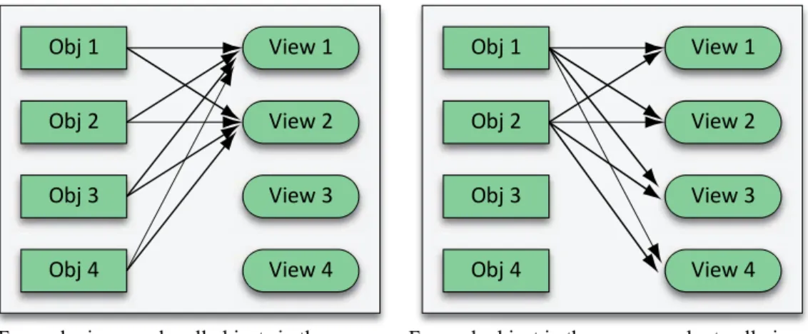
Once the rendering requirements of an object-view pair are known, there are two options for rendering the complete scene, as shown in Figure 12.8. In the first case, a specific view is activated only once, and all of the visible objects are rendered for that view. This process is continued until all of the views are com-pleted, and such an approach keeps the frame target “hot” to avoid frequent frame buffer swapping. In the second case, each object is activated only once, and it is rendered to all viewports sequentially, this time keeping the object “hot.” This approach can reduce vertex buffer or render state switches if view-specific geometry/render state data is not set up. Also, with this approach, the camera should cache projection and view matrix values for each view since the active view is changed very frequently. Depending on the setup of the scene and the number of views, the fastest approach may differ. A mixed approach is also pos-sible, where certain meshes in the scene are processed once into multiple views and the rest are rendered as a view-specific batch.
Figure 12.8. Rendering order considerations for multiview pipelines.
Obj 1 View 1 Obj 2 View 2 Obj 3 View 3 Obj 4 View 4 Obj 1 View 1 Obj 2 View 2 Obj 3 View 3 Obj 4 View 4
For each view, render all objects in the scene. For each object in the scene, render to all views.
12.8 Rendering Optimizations 193
Shared Data between Different Views
It is possible to make use of the coherence between different views during ren-dering as follows:
■ Most importantly, the same scene data is used to render the 3D scene (while this can be extended by using a multiview object LOD system). As a result, animations modifying the scene data need to be only applied once.
■ Object or light culling can be applied once per frame using a single shared frustum for multiview camera objects, containing the frustums of view-specific internal cameras.
In summary, only the effective drawing time of a specific viewport is affect-ed when multiview rendering is activataffect-ed. Other than an increase in the number of draw calls, the multiview composition step also costs render time, especially in low-end configurations such as mobile devices, and it should be optimally im-plemented. For example, on-target multiview buffers can be preferred to avoid an additional compositing phase if per-view compositing logic can be applied at render time by regular 3D pipelines. With such an approach, color write modes in the graphics pipeline can be used to set up regular anaglyph rendering, or stencil testing can be used to create per-view compositing patterns.
12.8 Rendering Optimizations
The aim of the multiview rendering optimizations discussed in this section is to provide some basic building blocks that can help programmers reduce total ren-dering time without sacrificing the perceived quality of the final result. Since, according to binocular suppression theory, one of the two eyes can suppress the other eye, the non-dominant eye can receive a lower quality rendering while not reducing the effective quality of the multiview rendering of a scene. A recent study [Bulbul et al. 2010] introduced a hypothesis claiming that “if the intensity contrast of the optimized rendering for a view is lower than its original rendering, then the optimized rendering provides the same percept as if it were not opti-mized.” This and similar guidelines can be studied, implemented and tested to be able to optimize a multiview rendering pipeline and thus to render more complex scenes in real time.
Multiview Level‐of‐Detail for Objects
In addition to the object distance parameter, engines supporting multiview archi-tectures can introduce a new detail parameter, the active view number, and use
this parameter to select the vertex data and the rendering state of an object. Lev-el-of-detail can then be implemented in one or more of the following ways:
■ Level-of-detail for object geometry. Simplified mesh geometries can be used for some of the views, reducing vertex processing time for complex meshes.
■ Level-of-detail for object materials. Different views can apply different
ren-dering techniques to a single object. The changes may involve reducing the number of rendering passes or the shading instruction complexity, such as switching between per-pixel and per-vertex shading or using different surface models for different views.
■ Level-of-detail for shaders. Shaders can execute different code paths based on the active view number, allowing more algorithmic approaches to reduc-ing shader complexities for higher numbers of views. This can also ease de-velopment of view-specific shaders and allow the creation of simplified routines for optimized views. Shader level-of-detail is a research area in it-self, and various automated techniques have also been proposed [Pellacini 2005]. This can equally be achieved by an application-specific solution, where different shaders are supported for the different views.
Multiview Level‐of‐Detail for Multiview Buffers
Using the customizability of off-target multiview buffers, it is possible to create buffers of different sizes for different views. One basic approach is to reduce the resolution of the target by half, practically reducing the pixel shading cost. The low-resolution buffers can be upsampled (magnified) during the composition phase, using nearest or linear sampling.
Since the low-resolution buffer on the same viewport will be blurry, it is ex-pected that the sharper view will dominate the depth perception and preserve the sharpness and quality of the overall perceived image [Stelmach et al. 2000]. Thus, it is advisable to use buffer level-of-detail options whenever the pixel shad-ing is time consumshad-ing.
We should also note that one of the two eyes of a person can be more domi-nant than the other. Thus, if the domidomi-nant eye observes a higher-quality view, the user experiences a better view. It is not possible to know this information in ad-vance, so user-specific tests would need to be performed and the system adjusted for each user. An approach that avoids dominant-eye maladjustment is to switch the low- and high-resolution buffer pairs after each frame [Stelmach et al. 2000].
12.9 Discussion 195
Other Optimization Approaches
As surveyed by Bulbul et al. [2008], graphics-pipeline-based and image-based optimization solutions have also been proposed. Graphics-pipeline-based optimi-zations make use of the coherence between views, or they are based on approxi-mate rendering where fragment colors in all neighboring views can be approximated from a central view when possible. In image-based optimizations, one view is reconstructed from the other view by exploiting the similarity be-tween the two. In these techniques, the rendering time of the second image de-pends on only the image resolution, instead of the scene complexity, therefore saving rendering computations for one view. Approaches have been proposed that are based on warping, depth buffers, and view interpolation [Bulbul et al. 2008].
12.9 Discussion
Multiview Scene Setup
Our architecture supports customization and extensible parameterization, but does not further provide guidelines on how to set the multiview camera parame-ters and scene in order to achieve maximum viewing comfort. In the first volume of Game Engine Gems, Hast [2010] describes the plano-stereoscopic view mech-anisms, common stereo techniques such as anaglyph, temporal multiplexing (shutter glasses), and polarized displays and discusses their pros and cons. Some key points are that contradicting depth cues should be avoided and that special care needs to be directed at skyboxes and skydomes, billboards and impostors, GUIs, cursors, menus in virtual 3D space, frame rate, view synchronization, and scene-to-scene camera setup consistency (such as focal distance). Viewers may have different eye separation distances and display sizes, and the distance of the viewer to the display can differ among different platforms. It should be kept in mind that creating the right 3D feeling is a process that requires a scalable tech-nical infrastructure (as presented in this chapter) and an analysis of the target platforms, the virtual scene, and animations.
Enabling/Disabling Multiview Rendering at Run Time
It is important to allow the user to select single-view rendering if the hardware supports it; some users [Hast 2010] may not be able to accommodate the mul-tiview content easily and may prefer single-view rendering because it can pro-duce a higher-quality image. The architecture natively supports switching
between single-view and multiview configurations through run-time attachment and detachment of multiview components (camera, buffer, and compositors as required) to a specific viewport on the render target. Viewport rendering logic that easily adapts itself to follow a single-view or multiview rendering pipeline is possible, and the implementation within OpenREng provides a sample solution.
Postprocessing Pipelines
Post-processing pipelines are commonly used, and their adaptation to multiview rendering can present a challenge. Most of the post-processing filters use spatial information about a fragment to calculate the output. The spatial information is partly lost when different views are merged into a single image. Thus, applying the same post-processing logic to the single composited image may not produce the expected output. If spatial data is not used, such as in color filters, the post-processing can natively interact with the results in separate views. However, fil-ters like high dynamic range and bloom may interact with spatial data and special care may need to be taken [Hast 2010]. In our architecture, the post-processing logic can be integrated into multiview compositor logic (shaders) to provide an-other rendering pass optimization.
Integration with Other Stereo‐Rendering APIs
As discussed in Section 12.5, our architecture can benefit from OpenGL quad-buffer stereo mode support directly. Yet there are other proprietary APIs that manage the stereo rendering at the driver level. As an example, Nvidia’s 3DVision API only supports DirectX implementations. Basically, the multiview rendering is handled by the graphics driver when the application follows specific requirements. Since such APIs offer their own abstractions and optimizations for stereo rendering, it may not be possible to wrap their APIs over our architecture.
3D Video Playback
To be able to playback 3D video over our architecture, it is possible to send the decoded 3D video data for separate views to their corresponding multiview buff-er color rendbuff-er targets and specify the composition by defining your own mul-tiview compositors. It is also possible to skip the mulmul-tiview buffer interface and perform the composition work directly using the decoded video data inside the multiview compositor merge routines.
Acknowledgements 197
Using Multiview Pipeline for Other Rendering Techniques
Our multiview rendering architecture can be extended to support soft shadow techniques that use multi-lights to generate multiple depth results from different locations. Yang et al. [2009] show an example of the multi-light approach for soft shadow rendering.
Acknowledgements
This project has been supported by 3DPHONE, a project funded by the European Union EC 7th Framework Programme.
References
[Bowman et al. 2004] Doug A. Bowman, Ernst Kruijff, Joseph J. LaViola, and Ivan Poupyrev. 3D User Interfaces: Theory and Practice. Reading, MA: Addison-Wesley, 2004.
[Bulbul et al. 2010] Abdullah Bulbul, Zeynep Cipiloglu, and Tolga Çap n. “A Perceptual Approach for Stereoscopic Rendering Optimization.” Computers & Graphics 34:2 (April 2010), pp. 145–157.
[Dodgson 2005] Neil A. Dodgson. “Autostereoscopic 3D Displays.” Computer 38:8 (August 2005), pp. 31–36.
[Hast 2010] Anders Hast. “3D Stereoscopic Rendering: An Overview of Implementation Issues.” Game Engine Gems 1, edited by Eric Lengyel. Sudbury, MA: Jones and Bartlett, 2010.
[Pellacini 2005] Fabio Pellacini. “User-Configurable Automatic Shader Simplification.”
ACM Transactions on Graphics 24:3 (July 2005), pp. 445–452.
[Stelmach et al. 2000] L. Stelmach, Wa James Tam, D. Meegan, and A. Vincent. “Stereo Image Quality: Effects of Mixed Spatio-Temporal Resolution.” IEEE Transactions
on Circuits and Systems for Video Technology 10:2 (March 2000), pp. 188–193.
[Yang et al. 2009] Baoguang Yang, Jieqing Feng, Gaël Guennebaud, and Xinguo Liu. “Packet-Based Hierarchal Soft Shadow Mapping.” Computer Graphics Forum 28:4 (June–July 2009), pp. 1121–1130.