Modeling and Reasoning about Design Alternatives of
Software as a Service Architectures
Bedir Tekinerdogan Department of Computer Engineering
Bilkent University Ankara, Turkey [email protected]
Karahan Öztürk, Ali Doğru Department of Computer Engineering
Middle East Technical University Ankara, Turkey
[email protected], [email protected]
Abstract— In general, a common reference architecture can be derived for Software as a Service (SaaS). However, while designing particular applications one may derive various application design alternatives from the same reference SaaS architecture specification. To meet the required functional and nonfunctional requirements of different enterprise applications it is important to model the possible design so that a feasible alternative can be defined. In this paper, we propose a systematic approach and corresponding tool support for guiding the design of SaaS application architectures. The approach defines a SaaS reference architecture, a family feature model and a set of reference design rules. Based on the business requirements an application feature model is defined using the family feature model. Selected features are related to design decisions and a SaaS application architecture design is derived.
keywords: SaaS Architecture Design; Design Guidelines; SaaS Tool Support
I. INTRODUCTION
Cloud computing is an emerging computing paradigm that has gained broad interest [3][13]. Unlike traditional enterprise applications that rely on the infrastructure and services provided and controlled within an enterprise, cloud computing is based on services that are hosted on providers over the Internet. In cloud computing, services are fully managed by the provider, and consumers can buy the required amount of services on demand, use applications without installation and access their personal files through any computer with internet access. The central hosting of both the application and data of consumers allows more flexible and efficient computing. In recent years the interest and use of cloud computing have accelerated with the significant developments in virtualization and distributed computing, as well as improved access to high-speed Internet and the need for economical optimization of resources.
The services that are hosted by cloud computing approach can be broadly divided into three categories: Infrastructure-as-a-Service (IaaS), Platform-as-a-Service (PaaS) and Service and
Software-as-a-Service (SaaS). In this paper we will focus on the Software as a Service context [8][9][11]. SaaS is a web-based, on-demand distribution model where the software is hosted and updated at a central site and does not reside on client computers. SaaS seems to be the most mature category of cloud computing, because it evolved from the application-service-provider model of software hosting. With SaaS, software applications are rented from a provider as opposed to purchasing for enterprise installation and deployment. Similar to the general benefits of cloud computing the SaaS approach yields benefits such as reduced cost, faster-time-to-market and enhanced scalability.
Obviously, an appropriate SaaS architecture design will play a fundamental role in supporting the cloud computing goals. Based on the literature we can derive the basic components required for SaaS. However, while designing particular applications one may derive various different application design alternatives [1] for the same SaaS architecture specification. Each design alternative may meet different functional and nonfunctional requirements. It is important to know the possible design so that a viable realization can be selected.
In this paper, based on a domain analysis process [4] we define a reference architecture for SaaS that represents the common components and their interactions with various SaaS platforms. Based on the reference architecture, we propose an approach for (1) modeling the design space of SaaS application design alternatives (2) and guiding the selection of these design alternatives based on the particular requirements. The approach consists of five steps: First, a reference feature model [4] is defined for the SaaS architecture that defines the possible features of SaaS as defined by the literature. Second, based on the feature model, required design decisions are defined and mapped to the SaaS feature model. Third, an application model is selected from the feature model for a desired SaaS application architecture and matching design decisions are extracted. Fourth, design decisions are converted to an instance of an internal-use architecture description language (ADL) [10] 2011 Ninth Working Conference on Software Architecture
that we introduced. Fifth, a diagram editor is provided and deployment diagram is generated from the ADL instance, so that, by the visual representation, design of the architecture will be quite easier and understandable.
The remainder of the paper is organized as follows. Section 2, describes the SaaS architecture. Section 3 defines the problem statement. Section 4 explains the approach for deriving SaaS application architecture from the reference architecture. Section 5 describes the tool support for the process. Finally in section 6 we discuss the problems.
II. SAASREFERENCE ARCHITECTURE
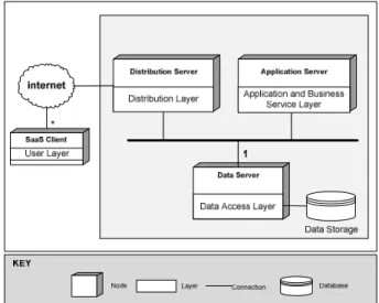
SaaS has been widely discussed in the literature and various definitions have been provided. In general when describing SaaS no specific application architecture is prescribed but rather the general components and structure is defined. Based on the literature we have defined a reference architecture for SaaS as given in Figure 1. SaaS has a multi-tier architecture with multiple thin clients. In Figure 1 the multiplicity of the client nodes is shown through the asterisk symbol (*). In alignment with the philosophy of SaaS clients do not have lot functionality installed but rather they rent and access these from providers on the internet. As such the cloud client includes only one layer User Layer which usually includes a web browser and/or the functionality to access the web services of the providers. This includes, for example, data integration and presentation.
We have defined the layers that are provided by the cloud (internet) as Distribution Layer, Business Service Layer, Application Service Layer, Data Access Layer, Data Storage Layer and Supporting Service Layer.
Figure 1. SaaS Reference Architecture including multiple thin clients and SaaS functionality deployed on internet
Distribution Layer defines the functionality for load balancing and routing. The Application and Business Service Layer represents services such as identity management, application integration services, and
communication services. Data Access Layer represents the functionality for accessing the database through a database management system. Data Storage Layer includes the databases. Finally, the Supporting Service Layer includes functionality that supports the horizontal layers and may include functionality such as monitoring, billing, security, and fault management. Each of these layers can be further decomposed into sub-layers.
III. PROBLEM STATEMENT
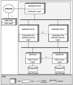
Although Figure 1 describes the common layers for SaaS reference architecture, it deliberately does not commit to specific application architecture. For example, the number of clients, allocation of the layers to different nodes, and allocation of the data storage to nodes is not defined in the reference architecture. Yet, while designing SaaS for a particular context we need to commit to several issues and make explicit design decisions that define the application architecture. Naturally, every application context has its own requirements and likewise these requirements will shape the SaaS application architecture in different ways. That is, based on the SaaS reference architecture we might derive multiple application architectures. For example, Figure 2 shows an alternative application architecture design that is derived from the reference architecture shown in Figure 1. The design supports the need for multi-tenancy by adopting a single database management system with a shared database and shared schemas for the tenants.
Figure 2. SaaS Application Architecture Alternative with Shared Data Servers and separated Single Distribution and Single Application Server
Figure 3. SaaS Application Architecture Alternative with Separate Data Servers for Tenants and separated Single Distribution and Single
Application Server
Figure 4. SaaS Application Architecture Alternative with Separate Data Servers for Tenants, Separate Application Server, and one Distribution
Server
Figure 3 shows an application architecture in which data storage is not shared but a separate Data Server provided for each tenant. Yet another design alternative is depicted in Figure 4 which shows a more complicated architecture in which Application Servers are also distributed to m number of multiple nodes to increase performance for multiple tenants.
Obviously these three design models are not the only alternatives and a considerable number of other design
alternatives may be derived from the same reference SaaS architecture. Each of these alternatives will be required for different requirements and constraints. Typical requirements that have an impact on the boundaries are the processing power need, different use of I/O, different configuration constraints, etc. All these requirements will not only impact the overall architecture but also have a direct impact on how each layer is designed individually. The architect will have to face many questions: What kind of distribution method will be selected? Should clustering be used for the application server? Which protocol will be used for communication? What will be the Identity Management for the system? How will the integration be made? How many tiers should be used?
SaaS application designers must be able to explicitly compare, evaluate and select among various alternatives based on the relative importance of the requirements and the constraints. Unfortunately, a systematic approach for depicting the space of possible application architectures and the selection of these alternatives is missing. True, while designing SaaS architectures, software engineers apply their knowledge, experience and intuition to compare the design alternatives. However, this process is primarily implicit and lacks explicit support. Without knowledge of the design space it is difficult to specify, compare and select the feasible application design alternative. As such we think that current SaaS methods should provide explicit means to determine and reason about the design space and the individual application design alternatives of SaaS.
IV. APPROACH FOR DERIVING APPLICATION ARCHITECTURE
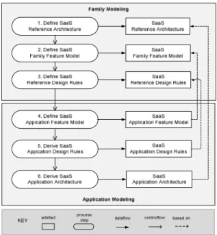
In this section we provide an approach for depicting the design space of application architectures and for selecting the appropriate design alternatives from this design space. The overall process is shown in Figure 5.
The process consists of two basic activities: Family Modeling and Application Modeling. In Family Modeling we define the reference models for SaaS including SaaS Reference Architecture, SaaS Family Feature Model, and SaaS Reference Design Rules. In Application Modeling, based on the reference models, we define the application models including Application Feature Model, Application Design Rules and Application Architecture. We explain the important steps in the following sections.
Figure 5. Approach for Deriving SaaS Application Architecture
A. Define SaaS Reference Architecture
The first step includes the definition of the SaaS reference architecture as defined in Figure 1. The SaaS reference architecture can be further specialized if needed.
B. Define SaaS Family Feature Model
Feature models are often used for defining the model of products for a given application domain [3]. Feature modeling has also been extensively used in domain engineering. Hereby, a feature model is a result of a domain analysis process in which the common and variant properties of a domain are elicited and modeled. In addition, the feature model identifies the constraints on the legal combinations of features. A feature model can thus be considered as a specification of the family.
Figure 6. Part of the Family Feature Model for SaaS Part of the family feature diagram for SaaS is given in Figure 6 (due to space limitations we have not depicted the complete feature diagram). In the feature diagram SaaS is the root feature that includes four mandatory
features: User Layer, Distribution Layer, Application Layer, and Data Layer. As such these features must be included in each SaaS application architecture. The SaaS family feature model is both an input for step 4 in which the application feature model is defined based on the SaaS family feature model, and an input for step 3 in which the design rules for the selection of the features are defined. C. Define SaaS Reference Design Rules
The SaaS family feature diagram represents the possible sets of feature that are required. In addition, a selection of each feature will shape the SaaS application architecture and as such represents a design decisions. We need instructions to generate deployment diagram automatically. We derive these instructions from the rules which we call design rules. For this reason, after defining the family feature model we define the corresponding design rules and map them to the selection of the features. The syntax of the design rules is expressed in Figure 7.
Figure 7. Design Rule Definition Language
Many features have cross-cutting influences on the software architecture. In addition to this, a feature may not lead to have an effect on the architecture. On the contrary, a set of features may affect the architecture. Moreover, the features may have different impacts according to the context. To overcome these problems, we used many-to-many mapping model between the design rules and the features. The Design Rule Editor enables user to group the features and make logical operations such as “and, or, not”. Thus, the user can define the rules in a condition like “if [(feature-1 and feature-2) or feature-3] selected then apply command”. Also the user can define multiple design rules for the same condition and later he will be able to select the appropriate one for corresponding condition according to the context.
Using the design rule definition language we have specified around 30 design rules for the selection of the features in the family feature model. An example set of the rules is given in Figure 8.
D. Define SaaS Application Feature Model
Once the SaaS reference architecture, the family feature model, and the corresponding design rules are specified we can start the definition of the SaaS application architecture. The input for this step is basically the family
feature model. Based on the requirements of the stakeholders important features are selected from the SaaS feature model.
E. Derive SaaS Application Design Rules
The input for this step is both the SaaS reference design rules and the application feature model. Based on the features in the application feature model we derive the corresponding application design rules from the SaaS reference design rules.
1. if “Client.Certified Partner” selected, then add component
<<execution>> web service on <<device>> Integration Server
2. if “Distribution Layer.Firewall” selected, then add
<<device>> firewall
3. if “Load Balancer.Type.Software Based” selected, then add
<<device>> typical server to be used as load balancer 4. if “Load Balancer.Firewall” selected, then remove
<<device>> Firewall
5. if “Application Server.Clustering” selected, then add <n>
<<device>> application server
6. if “Multi-Tenancy.Separate DB” selected, then add <n>
<<device>> Database Server including
<<execution>> Database Engine <<artifact>> Database
7. if “Identity Management.Single Sign On” selected, then add
<<execution>> Kerberos Authentication Server
Figure 8. Design Rules based on features in Family Feature Model
F. Derive SaaS Application Architecture
The application design rules from the previous step define the steps to design the architecture. Based on the reference architecture and the application design rules we define the SaaS application architecture.
V. TOOL SUPPORT AND EXAMPLE
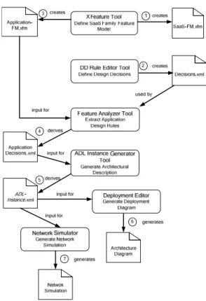
Although the steps of the process in the previous section can be performed manually, we have developed a set of tools to assist the SaaS application design process. Figure 10 depicts the data flow and order of the steps including the tools. In the following subsections we explain the tool support activities together with a running example.
G. Feature Modeling
An important part of the process consists of feature modeling. We have used the tool XFeature [12]to define both the SaaS reference feature model and to derive the application feature model. In fact the feature model as defined in Figure 6 is a snapshot of the XFeature model. In Figure 10 the family feature modeling is defined as step 1, while the application feature modeling is defined in step 4.
Using XFeature it is possible to edit and extend the feature diagram. XFeature has a graphical editor and represents the hierarchical structure visually. The resulted family feature model is stored in xml files. The family feature model is stored in the file SaaS-FM.xfm; the
application feature model is stored in Application-FM.xfm.
XFeature allows defining constraint through the features. In case of deriving an application feature model from the family feature model, the tool checks these constraints and warns the user if there is any inconsistency. So, XFeature guarantees that the application feature model is valid and consistent.
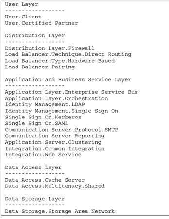
In Figure 9 we illustrate the feature modeling example with selected features based on the family feature model.
User Layer --- User.Client User.Certified Partner Distribution Layer --- Distribution Layer.Firewall
Load Balancer.Technique.Direct Routing Load Balancer.Type.Hardware Based Load Balancer.Pairing
Application and Business Service Layer ---
Application Layer.Enterprise Service Bus Application Layer.Orchestration
Identity Management.LDAP
Identity Management.Single Sign On Single Sign On.Kerberos
Single Sign On.SAML
Communication Server.Protocol.SMTP Communication Server.Reporting Application Server.Clustering Integration.Common Integration Integration.Web Service Data Access Layer --- Data Access.Cache Server Data Access.Multitenacy.Shared Data Storage Layer
---
Data Storage.Storage Area Network Figure 9. Example Feature Model derived from
Family Feature Model
Note that in Figure 9 there are no variant features, the features for the specific business requirements have determined the selected features. As an example we can observe that for the Distribution Layer the features Firewall, Direct Routing, Hardware Based and Paring have been selected.
Figure 10. Tool Support Data Flow
H. Design Rule Modeling
To represent design rules we have developed a tool called Design Rule Editor which is shown in Figure 11. The tool supports the earlier defined Design Rule Definition Language and we can use it to specify the design rules for the features in the family feature model.
Design Rule Editor uses the SaaS Family Feature Model file (SaaS-FM.xfm) created in the previous step. All features from the feature model are listed and the user selects one of the features and defines the rule about that feature.
Figure 11. Design Decision Rule Editor
As an example, in Figure 11 we show the definition of the rule "if Integration Model.Common_Integration is selected then add execution 'Web Service' on device Integration Server". In this case, the designer aims to provide Web services for data integration to its clients instead of implementing customer specific integration services and the rule dictates that there should be a piece of software as web services on the specified device. In the Display tab of the tool, the human-readable form of the rule is showed and the user can add note or a description of the rule. With this rule editor we have specified all the reference rules based on the family feature model which is stored in the file Decisions.xml as shown in Figure 10.
I. Associating Design Decisions to Features
In the previous steps we have generated an application feature model (stored in Application-FM.xfm) and we have defined the design decisions rules (stored in Decisions.xml). In this step we use the Feature Analyzer Tool to determine which design rules will be used for the features of the application feature model. The Feature Analyzer Tool first reads the selected features from the Application-FM.xfm file. Then it checks the condition parts of the design decision rules to determine whether there is matching rules. After the tool scans all the design rules, it brings only the matching ones.
For the example application feature model in Figure 9 the design rules have been derived by checking the reference design rules and matching it with the selected features. We show, as an example, the set of the derived rules for the Application and Business Layer and the Data Access and Storage Layer features:
if "Application Layer.Enterprise Service Bus" selected then add <device> ESB including <execution> ESB Services
if "Application Layer.Orchestration" selected
then add <execution> Orchestration Service on <device> ESB
if "Identity Management.LDAP" selected then add <device> LDAP server
if "Identity Management.Single Sign On" selected
then add <device> "Identity Management Server" including <execution> Identity Management System
if "Single Sign On.Kerberos" selected then add <device> Kerberos Server
if "Application Server.Clustering" selected then
add <n> <device> Application Server
if "Integration.Web Service" selected then add <device> Integration Server
if "Integration.Common Integration" selected
then add <execution> Web service on <device> Integration Server
if "Data Access.Cache Server" selected then add <n> <device> Cache Server
if "Data Access.Multitenacy.Shared" selected
then add <1> <execution> DBMS
if "Data Storage.Storage Area Network" selected
then <n> <device> Storage Device
After correlation of the design rules and features, the next step is creating an instance of the family, which is called the application model.
J. Generation of the Application Architecture
In this study, we aimed to provide guidance for reasoning about alternative SaaS architectures. So far, we were able to define an application model from the family and we need to represent the corresponding architecture of the application model.
The design decision rules, we mentioned before, are useful for exposing the architecture. Since application model derives from the family model, it also inherits the existing attributes. Within the application model features, there are references to design rules as attributes. Here, we introduce another tool, Feature Analyzer which takes as input both the application model file (Application-FM.xfm) and design decision rules file (Decisions.xml). The tool automatically extracts the attributes of the features, finds references to design rules and links it to those rules. As a result, all features of the application model are represented graphically as a tree-like hierarchical structure and the corresponding design decision rules are displayed.
Figure 13. Feature Analyzer Tool
As shown in Figure 13, on the left side of the panel, the features are displayed for a specific alternative application model. In the case of selecting a feature, the corresponding design rule is displayed at the right side. Remember that, Design Rule Editor allows adding notes for the features and the notes are also displayed on the panel.
The next step is transforming these design rules to an architecture specification. For this, we have developed a simple architecture description language (ADL) [10]. This language has only basic types for describing the architecture: device, execution and connection. The ADL instance is used internally, that is to say, the user does not write a description manually. We have developed another tool, Architecture Generator, which takes application specific design rules and converts them to architectural
description in xml format. A part of the architectural description is shown in Figure 14 which is generated by the Architecture Generator Tool.
Figure 14. An Example of ADL instance
K. Generating Deployment Diagram for SaaS Architecture
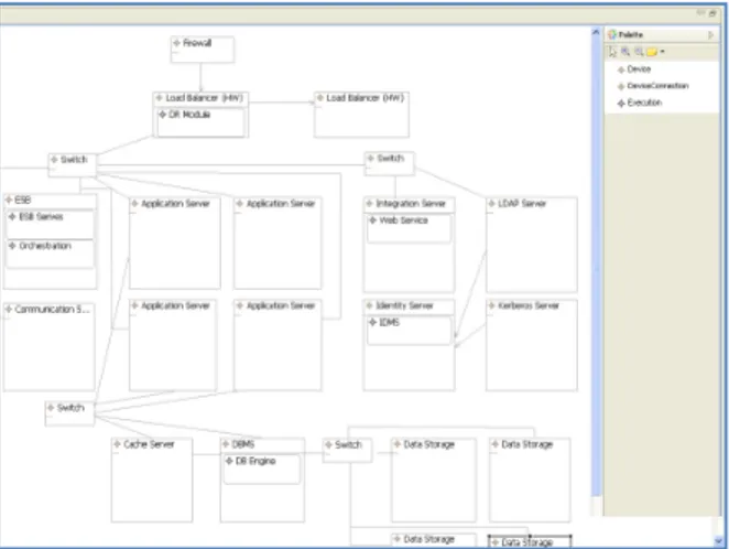
The final step is showing a graphical view of the architecture. Deployment diagram is a static view of the hardware, the software running on that hardware and the relationship between them. We have chosen the deployment view of the architecture to display, because deployment diagram is also very useful for system engineering. It can be used for analyzing quality attributes such as scalability, performance, maintainability, portability, and so on [2]. We have developed an eclipse plug-in [6], an editor, which is capable of both drawing deployment diagram automatically from ADL instance and enabling user for editing the generated diagram.
We used Model Driven Architecture (MDA) and Eclipse Graphical Modeling Framework (GMF) [5] for developing a deployment diagram editor. MDA provides high level abstraction, platform independent modeling approach and uses a Domain Specific Language. GMF helps to define domain models and represent them graphically based on MDA.
Figure 15. Deployment Diagram Editor
In our ADL, we have basic elements to define architecture. To develop the deployment diagram, we also need Domain-Specific Language (DSL) elements that correspond to the ADL elements. Thus, device, execution and connector model and meta-model files are defined in
GMF. By using the model and meta-model files, GMF generates the tool code.
The graphical editor generates the deployment diagram automatically from the architectural description which is generated in the previous step. First, the editor parses the ADL instance components than determines the layout of the components and arranges the position of the components.
After the deployment diagram is generated automatically, the user can modify the diagram arbitrary. Figure 15 illustrates the visual representation of the architecture by the deployment diagram editor for the example application feature model of Figure 9and the derived application design rules of Figure 12.
VI. CONCLUSION
Based on the literature we can define a common SaaS architecture that includes the concepts and relations among the concepts to derive SaaS application architectures. Selecting the appropriate SaaS architecture is important to meet the specific business requirements. Unfortunately the current state-of-the art does not provide an explicit approach for guiding the selection of the application architecture.
We think that there are two important contributions in the paper. First of all we provide a systematic approach for modeling SaaS reference architecture and deriving different SaaS application architecture based on the selections of features from a family feature model. The mechanism for distinguishing the modeling between family modeling and application modeling appeared to be very useful. In the family modeling part we actually applied a domain engineering process and defined the reference architecture, the family feature model and the reference design rules. The reference architecture actually defines the space of application architectures. The family feature model defines the possible features for SaaS applications, and it appeared that we can relate these to specific architectural decisions. Based on the derived architectural decisions we could derive the specific application architecture.
A second important contribution is the toolset that we have developed for supporting the process. With the toolset we actually store the complete derivation of the application architecture from the feature models. The application features, the derived design rules and the eventual application architecture are linked to each other and as such the design decisions and the requirements feature selection for the application architecture can be easily traced. By defining multiple application architectures based on different application feature models we can even compare multiple alternatives and based on this select the most feasible alternative.
There are also many possible extensions possible for this work. Our future work will in the first place focus on applying the process within an industrial context. We will also extend our toolset and provide a full integration of the tools within an Eclipse development environment.
Finally, we will also focus on nonfunctional requirements in selecting application architectures [2]. In this paper we have mainly focused on functional feature set as defined in the family feature model. We think that we can equally focus on quality feature models to derive the application architecture.
VII. REFERENCES
[1] F. Bachmann, L. Bass, M. Klein, Deriving Architectural Tactics: A Step Toward Methodical Architectural Design, CMU/SEI-2003-TR-004, ADA413644, Pittsburgh, PA, March 2003.
[2] S. Balsamo, A. Di Marco, P. Inverardi, M. Simeoni, Model-Based Performance Prediction in Software Development: A Survey, IEEE Transactions on Software Engineering, vol. 30, no. 5, pp. 295-310, May 2004.
[3] R. Buyya, C.Shin Yeo1, S. Venugopal, J. Broberg, and I. Brandic. Cloud Computing and Emerging IT Platforms: Vision, Hype, and Reality for Delivering Computing as the 5th Utility. Future Generation Computer Systems, Vol. 25, No. 6. pp. 599-616. June 2009.
[4] K. Czarnecki and U. Eisenecker. Generative Programming: Methods, Tools, and Applications, Addison Wesley, 2000.
[5] Eclipse Modeling Framework Web Site, http://www.eclipse.org/gmf/
[6] Eclipse official web site, http://www.eclipse.org, ssaccessed 2008. [7] M. Godse, S. Mulik, An Approach for Selecting Software-as-a-Service (SaaS) Product, pp.155-158, 2009 IEEE International Conference on Cloud Computing, 2009.
[8] G. Goth. Software-as-a-Service: The Spark That Will Change Software Engineering? IEEE Distributed Systems Online, vol. 9, no. 7, 2008.
[9] H. Liao. Design of SaaS-Based Software Architecture, niss, pp.277-281, 2009 International Conference on New Trends in Information and Service Science, 2009.
[10] N. Medvidovic and R. N. Taylor. A classification and comparison framework for software architecture description languages. IEEE Trans. Software Eng., 26(1):70–93, 2000.
[11] M. Turner , D. Budgen, P. Brereton, Turning Software into a Service, Computer, v.36 n.10, p.38-44, October 2003.
[12] XFeature official web site, http://www.pnp-software.com/XFeature, accessed 2010.
[13] M.A. Vouk. Cloud Computing – Issues, Research and Implementations. Journal of Computing and Information Technology - CIT 16, 4, 235–246, 2008.