FAKULTÄT MASCHINENBAU
Master of Science in Manufacturing Technology
Lehrstuhl Für Kunststofftechnologie
Prof. Dr.-Ing. Markus Stommel
Master Thesis
Material selection for a strut bearing using finite
elements analysis
by
Enver Caliskan
Registration Number: 198684
Supervisors:
Prof. Dr.-Ing. Markus Stommel
Assist. Prof. Dr. Mehmet Gokhan Gokcen
M. Sc. Kevin Breuer
Abstract
Material selection is a crucial aspect of any product. There are huge number of possible materials. So in order to meet the necessary requirements; selecting the optimum material for the optimum design is what makes a product safe, comfortable and profitable. Plastic materials are a huge family of materials and their usage have been rapidly increasing especially in the automotive industry where many plastic material have replaced metals. Their lower weights and increased mechanical properties of the plastic composites make them an ideal selection for many application. An example for the usage of plastics in the automotive is the plastic components used in the vehicle suspension systems.
Suspension systems play a vital role in an automobile. It is responsible for offering a safe and comfortable ride. Suspension system dampens the vibrations caused by uneven terrain surfaces and prevents transmitting those excitations to the passenger cabin thereby providing a safe and comfortable drive. It carries out these functions as a result of the harmonic work between components such as spring and shock absorber. There are various types of suspension systems depending on the type of vehicle. The most commonly used ones are the double wishbone suspension and the MacPherson strut suspension.
In the frame of this thesis work; components called upper spring seat and upper cap which are subcomponents of a component called strut bearing in the MacPherson strut suspension system were studied to select the optimum plastic materials for them. Literature research activities were conducted about the main topics of the study such as plastics, plastic injection and suspension systems. Design activities were carried out via SolidWorks to help create different designs to see which design version offers the lowest weight without altering the mechanical properties in a negative way. Then Ansys static structural analysis activities were conducted to obtain data such as stress, strain and deformation. Another tool that was used was Moldflow which was used to simulate the flow of the molten plastic. For the material selection process; various material databases were investigated to find possible materials. The mechanical properties of those materials were compared to each other.
In the end; as result of all the research, design, analysis and simulation activities; material selection and a final design selection activities were conducted. The selected new materials offer very good mechanical properties and the design modifications also lead to a better design with lower overall weight.
Keywords: Plastic, Suspension, Composites, MacPherson Strut, Material Selection, Design, Analysis, Simulation, Glass Fibre
Acknowledgements
This Master thesis work was carried out according to the collaboration between TU Dortmund, Turkish – German University and Oyak Renault. It is the final condition for my graduation from the international joint degree program called the master of science in manufacturing technologies (MMT).
It has been an incredible experience to take part in this program and fulfil my lifelong dream of doing my master abroad. I have been fortunate enough to meet with very interesting friends from all around the world and get a first class education at a high profile university.
So this master thesis is in a way a farewell to a wonderful period of my life and a welcome to the next exciting chapter. First and foremost; my deepest appreciation for everything they have done for me my entire life to my loving and supporting family of Huseyin, Zahide, Fidan and Songul Caliskan. A special thanks goes to my first ever niece Arin who will join our little family pretty soon.
I would like to thank Prof. Stommel for giving me the chance to conduct my thesis with them. Mr. Kevin Breuer who was also my supervisor from TU Dortmund has been really helpful and understanding. So I would like to thank him for his guidance.
From the Turkish – German University; Assist. Prof. Dr. Mehmet Ipekoglu who has been with me from the beginning of this master and helped me for the last 3 years. He has been very inclusive and has always given his full attention. I thank him for his constant guidance and supervision. Also to Assist. Prof. Dr. Mehmet Gokhan Gokcen; I would like to thank him for his supervision for this thesis work.
Ms. Ceren Bilgili who was my supervisor at the Oyak Renault plant has been really understanding and supportive throughout this thesis work. She has provided me with highly valuable information regarding my work and has been a huge help. I offer her my sincere gratitude for everything she has done.
To all my classmates, teachers and friends from TU Dortmund; thank you for the amazing journey from someone who always says “it is not about the destination, it’s all about the journey”.
And finally; a special thank you to a very special person - Canan Dogan - who is always there for me.
Contents
1 Introduction... 1
2 State of the Art ... 5
Plastics ... 5
2.1.1 Plastic Material Categorization ... 7
2.1.2 Morphology of Plastics ... 10
2.1.3 Plastic Composites ... 11
Plastic Injection Moulding ... 14
Suspension Systems ... 17
2.3.1 Suspension Systems Classification ... 19
2.3.2 Suspension System Components and Types ... 20
3 Design and Analysis Activities ... 32
Upper Spring Seat ... 33
3.1.1 Design Activities ... 33 3.1.2 Analysis Activities ... 38 3.1.3 Moldflow Simulations... 46 Upper Cap ... 49 3.2.1 Design Activities ... 49 3.2.2 Moldflow Simulations... 51 4 Material Selection ... 52 5 Results ... 54
Upper Spring Seat ... 54
5.1.1 Material Selection ... 57
Upper Cap ... 69
5.2.1 Material Selection ... 69
Evaluation of The Selected Materials and Design Improvements ... 72
5.3.1 Upper Spring Seat ... 72
5.3.2 Upper Cap ... 74
6 Conclusion and Outlook ... 75
Conclusion ... 75
Outlook ... 76
List of Figures
Figure 1.1: Procedure followed for the thesis work 3
Figure 2.1: Plastic parts in a vehicle 5
Figure 2.2: Molecular structure of a polymer made of monomers 5
Figure 2.3: Molecular structure of plastic types 7
Figure 2.4: Molecular structure of thermoplastics 8
Figure 2.5: Thermoplastic materials 8
Figure 2.6: Molecular structure of thermoplastics 9
Figure 2.7: Molecular structure of an elastomer 9
Figure 2.8: Crystalline and amorphous structure types 11
Figure 2.9: Illustration of plastic reinforcements 13
Figure 2.10: Plastic production methods 14
Figure 2.11: A plastic injection machine example 15
Figure 2.12: Plastic injection cycles: a) closing, b) injection, c) cooling, d) ejection 15
Figure 2.13: Injection unit of an injection moulding machine 16
Figure 2.14: Injection unit screw types 16
Figure 2.15: Component examples in an automobile 17
Figure 2.16: Suspension system in an automobile 18
Figure 2.17: Suspension system example and its main components 18
Figure 2.18: Non independent suspension system example 19
Figure 2.19: Independent suspension system illustration 20
Figure 2.20: Simple illustration of a vehicle suspension system 21
Figure 2.21: Leaf springs used fur suspension in a heavy vehicle 22
Figure 2.22: Illustration of leaf springs in suspension systems 22
Figure 2.23: Coil spring types 22
Figure 2.24: A suspension system with a coil spring 23
Figure 2.25: Shock absorber example 23
Figure 2.26: The schematic of a shock absorber 24
Figure 2.27: An example of an anti - roll bar in a suspension system 25
Figure 2.28: Solid axle beam suspension with leaf springs 25
Figure 2.29: Solid axle beam suspension with coil springs 25
Figure 2.31: Air suspension system example 27 Figure 2.32: Illustration of a double wishbone suspension 27 Figure 2.33: Double wishbone suspension system illustration 28 Figure 2.34: Audi R8 with a double wishbone suspension system 29 Figure 2.35: MacPherson strut suspension system illustration 29
Figure 2.36: A strut example 30
Figure 2.37: Audi TTRS with MacPherson strut type suspension 30 Figure 2.38: Illustration of a MacPherson strut suspension and its components 31 Figure 3.1: Design and analysis activities procedure 32 Figure 3.2: Strut bearing used by Renault and the function of the components 32 Figure 3.3: MacPherson strut suspension assembly and components 33 Figure 3.4: Isometric view of the MacPherson strut suspension system design 34 Figure 3.5: Front view of the MacPherson strut suspension design 34 Figure 3.6: Current upper spring seat design 35 Figure 3.7: Modified upper spring seat designs – Design Version 1 36 Figure 3.8: Modified upper spring seat designs – Design Version 2 37 Figure 3.9: Modified upper spring seat designs – Design Version 3 38 Figure 3.10: Forces applied to the upper spring seat for Ansys analysis 29
Figure 3.11: Details of the applied forces 40
Figure 3.12: Boundary condition of the upper spring seat and its details 40 Figure 3.13: Ansys static structural analysis settings and parameters 40 Figure 3.14: An example from Ansys analysis activities 41 Figure 3.15: Inner stress distribution of the upper spring seat 41 Figure 3.16: Ansys analysis results of design version 1 42 Figure 3.17: Further Ansys analysis results of design version 1 43 Figure 3.18: Ansys analysis results of design version 2 44 Figure 3.19: Further Ansys analysis results of design version 2 45 Figure 3.20: Ansys analysis results of design version 3 46 Figure 3.21: Solid model of the part and the location of the gate 46 Figure 3.22: Moldflow simulation settings used for simulations 47 Figure 3.23: List of results obtained from the applied settings via Moldflow 47 Figure 3.24: Moldflow simulations of the upper spring seat 48 Figure 3.25: Design of the upper cap 49 Figure 3.26: Upper spring seat and upper cap assembly 50
Figure 3.27: Moldflow simulations for the upper cap 51 Figure 4.1: Process flow of this thesis work 53 Figure 5.1: Illustration of the channels on the top surface of the upper spring seat 54 Figure 5.2: Moldflow simulations with Zytel HTN 51G45HSL BK083 65 Figure 5.3: Moldflow simulations with Grivory HT1V-45 HY black 9205 66 Figure 5.4: Moldflow simulations with ForTii Ace MX52 66 Figure 5.5: Moldflow simulation results of the current material 66 Figure 5.6: Graphs illustrating the properties of ForTii MX15HR 67 Figure 5.7: Final design selection and analysis results with the selected material 68 Figure 5.8: Moldflow simulations of the possible materials for the upper cap 71 Figure 5.9: Stress – strain values of EqooPaXX Q-150-D 72 Figure 5.10: Charts illustrating the effects of design and material changes 73 Figure 5.11: Charts illustrating the effects of material changes for the upper cap 74
List of Tables
Table 2.1: Comparison of Natural and Synthetic Polymers 6 Table 2.2: Thermoplastic and Thermoset Material Examples 7 Table 2.3: Properties comparison of thermoplastics, thermosets and elastomers 10 Table 2.4: Properties comparison of glass fibre types 13 Table 3.1: Ansys Static Structural Analysis Details 40 Table 5.1: Overall Weight of Design Modifications – Design Version 1 56 Table 5.2: Overall Weight of Design Modifications – Design Version 2 56 Table 5.3: Overall Weight of Design Modifications – Design Version 3 56 Table 5.4: Ansys Static Structural Analysis Results – Design Version 1 56 Table 5.5: Ansys Static Structural Analysis Results – Design Version 2 56 Table 5.6: Ansys Static Structural Analysis Results – Design Version 2 57 Table 5.7: Material Properties of Grivory PA6T/6I%50GF - Durethan PA6%60GF 57 Table 5.8: Possible Materials for the Upper Spring Seat and Their Properties 58 Table 5.9: Overall Weight and Safety Factor Values of Grivory %50 GF and Durethan
%60 GF for Selected Design Modifications 61
Table 5.10: Safety Factor and Overall Weight Values of Selected Designs Based on
Possible Materials and Their Properties 62
Table 5.11: Evaluation of the Best Possible Material Selections and Design
Modifications for the Upper Spring Seat 64
Table 5.12: Possible New Materials for the Upper Cap 69 Table 5.13: Moldflow Simulation Results of Possible Materials for the Upper Cap 70 Table 5.14: Comparisons Between The Current Material and The ForTii MX15HR 73
Formula Symbols and Abbreviation
Formula Symbols
Symbol Unit Description
F Newton Force
t Second Time
T Degree Temperature
d 𝑔𝑟 𝑐𝑚⁄ 3 Density
E MPa Tensile Modulus
m gr Weight 𝜎 MPa Stress Abbreviation Abbreviation Description PA Polyamide PE Polyethylene PS Polystyrene PVC Polyvinylchloride PC Polycarbonate
PET Polyethylene terephthalate
PP Polypropylene
PUR Polyurethane
ABS Acrylonitrile butadiene styrene
PEEK Polyether ether ketone
Abbreviation Description
TPU Thermoplastic polyurethane
PPA Polyphthalamide
PTFE Polytetrafluoroethylene
PPS Polyphenylene sulphide
PK Polyketone
1
Introduction
In order to have economic success and a profitable business and more importantly maintain that success in today’s globally challenging industry; the products have to satisfy the customer demands on so many levels and also they have to be produced in a way that the production costs are at the minimum. So the main priorities of any production process are to produce the products with high quality and low costs. Customers have many expectations such as high quality, safety, functionality, long service life, appealing design and low cost. The products have to satisfy all these criteria along with making a profit for the producer. Because of the high expectations and the competition in the industry it is vital for the companies to constantly work on improving themselves. Therefore; the companies invest a lot of their resources into research and development activities to define the possible improvement ways with innovative ideas.
One of the most important aspect of production processes is the material selection. Choosing the right material for the right job is the key to a high quality product. In layman terms it is essential to know what you are working with in order to be successful. So knowing different material groups, their properties, their advantages and disadvantages is a must. Because of this; the material science is today’s one of the most important and rapidly growing industry with new information and materials coming almost on a daily basis. Besides it is importance for the industries; the material science is also a major field for the scientific research activities.
There are different types of material and each of them have different uses. Their properties, their design, their production method and their service life vary greatly from each other. There are plenty of material characterization test methods developed to help define the material properties which are essential for material selection process. With the data obtained from these tests; the materials can be compared to each other and in doing so the optimum material can be selected for the right job. Material selection is the main focus of this thesis work. As part of the continuous improvement activities; components are constantly evaluated for improvement possibilities. This improvements can be accomplished via design changes, process changes, assembly changes or material changes. As the components that are the topic of this thesis work
are not manufactured on site; changes to the production process are not possible. Changing the assembly is also not optional as these parts are assembled to various other components and any sort of change would require changing the design and assembly of every other component as well. Therefore; the only way these improvement activities can be carried out are via design and material changes. The designs of the parts were evaluated to see if it would be possible to reduce weight without altering the mechanical properties. But the extent of changes can be made were limited as this would affect the overall assembly. Hence; material selection offers the greatest possibility for improvement activities. A new material with better mechanical properties would accomplish the improvement goals without affecting the design, process or the assembly. It is possible to select a material with good mechanical properties such as strength and a low density which would also mean reduced overall weight.
So in summary; main focus was selecting new materials with better properties compared to current ones and improving the design without altering the assembly if possible. But material selection is a rather complex process as there are countless choices. Their properties vary in a great range and their microstructure also varies a lot. So optimum material selection requires comparing materials according to their properties, their molecular structure, their production processes, their operation conditions and so on. For this thesis work; plastic materials were investigated thoroughly. Plastic material types were investigated based on their properties. Especially the strength of plastic composites were studied. The filler content and the type of main compound define the final properties of the part. All these parameters combine and define whether the material in question would deform plastically under the applied loads and boundary conditions or it can withstand these conditions and offer a safe product.
This thesis focuses on material selection for a strut bearing using finite elements analysis. The thesis work is conducted at Oyak Renault plant in Turkey which is a part of Group Renault family. It comprises general research activities about suspension systems, plastic materials, plastic injection process and finally design and analysis activities for the material selection. The procedure followed for this thesis work is illustrated in Figure 1.1 below and each step is explained in detail.
Figure 1.1: Procedure followed for the thesis work
In the frame of this thesis work; firstly literature research activities were conducted to gain the necessary fundamental information about plastics, plastic types and their properties. Also plastic injection process was studied to understand the process, the machines, the moulds etc. Then suspension systems, suspension system components and their functions were studied. Different suspension types were compared to each other. Most important part of the research activities was the material properties and comparison activities. Different material databases were studied to check the properties of different material types.
Secondly design activities were conducted using software such as SolidWorks and UniGraphics. Current design was modified in order to see if the weight can be reduced and analyse how the properties change according to the design modifications. The aim was to decrease the weight if possible without affecting the mechanical properties. Lastly different designs were analysed with different materials using Ansys software. Materials were appointed to the designs and the effects of the loads applied were studied to select the optimum material. Moldflow simulation activities were also conducted to simulate the plastic flow.
The strut bearing is a component in the suspension system of automobiles. Automobiles have many complicated systems integrated together to work as a unit. Steering system, braking system, cooling system, suspension system etc. are some examples and each of them has their own function.
Literature Research
Design & Material Selection
Finite Elements Analysis &
Moldflow Simulation
Suspension system is responsible for providing a safe and comfortable ride. It serves as a dampening mechanism by absorbing the shocks created by the road surface and not transferring those to the passenger cabin. Suspension system makes sure that the tires do not lose contact with the road surface which is vital for the safety as losing contact between the road and the tires could lead to serious accidents.
Depending on the type of vehicle; the suspension system might vary. Different suspension systems are used based on the vehicle type. Heavier vehicles such as trucks and buses do not use the same type of suspension as the passenger vehicles. There are options even with in the passenger vehicles as well. The suspension type also varies depending on whether it is used on the front or the rear of the vehicle. There are different types of components in a suspension system. While some components are specific to certain suspension types; some components such as shock absorber, spring, dustboot, anti - roll bar etc. are common in most of the suspension system types.
As it was stated earlier; the main focus of this work is the material selection process. The components in question are made of plastics and therefore another important part of this thesis work will be plastic materials. Plastic material usage has been growing rapidly and in so many industries particularly automotive and aviation plastic materials are replacing metals due to their high advantages such as low weight, high strength, high stiffness, good corrosion resistance as well as their low costs. Weight reduction is a huge goal for any product and is one of the most popular terms in the automotive industry in the recent years. Due to their low costs and high mechanical properties plastic materials are gaining more and more attention. Furthermore there are plenty of different plastic material types which offers a wide range of selection and their properties can be improved by using different kind of reinforcements such as chalk, talc, carbon fibre and glass fibre. [1]
2
State of the Art
The aim of this chapter is to provide the fundamental data regarding the subjects of this thesis work. Firstly the basics about plastic materials, composite plastics and plastic injection process are explained. Secondly the suspension system, suspension system components, different suspension types etc. are explained to create the necessary background. Then strut bearing which is the topic of this thesis is explained.
Plastics
Usage of plastic materials has increased rapidly due to their good mechanical properties and their relatively low costs. It is today’s one of the biggest industries. According to data from European Plastic; the plastic industry had a turnover of 350 billion Euros in 2017. Same data showed that 350 million tonnes of plastics were produced in 2017. There are around 60000 companies with more than 1,5 million people working in the plastic industry [2]. An example of the plastic parts used in an automobile is showed in Figure 2.1 below.
Figure 2.1: Plastic parts in a vehicle [3]
Plastics are a popular choice nowadays and they are very resource efficient materials made of polymeric materials. Polymer is a chemical compound and it is made of many small particles known as monomers. The molecular structure of a polymer is illustrated in the Figure 2.2. [4]
Polymeric materials offer a variety of choices and there is huge differences between different polymer types. Polymers can be derived from a number of different sources. Based on the source of origin; polymers can be categorized as organic, inorganic, natural or synthetic. Natural polymers are materials that exist in the nature or they can be extracted from various plants or animals. This type of polymeric materials are vital for our daily life because the human forms are based on them. Some examples of natural polymers are proteins, nucleic acid, cellulose, natural rubber, wool and silk. [4] In contrast to natural polymers; synthetic polymers are man-made. They are produced in laboratories to be used in many different areas. They are usually derived from fuel based resources in controlled environments but there are also plenty of bio based plastics nowadays. With the use of some production processes the monomers are bonded together to form a molecular chain which are the synthetic polymers. The process of bonding the monomers is known as polymerisation and the number of monomers in these molecular chain is referred as the degree of polymerisation. Some examples for synthetic polymers are polyamides (nylon), polyethylene (PE), polystyrene (PS), polyvinylchloride (PVC), synthetic rubber, teflon, epoxy and so on. [5]
In Table 2.1 a comparison between natural and synthetic polymers is given. Table 2.1: Comparison of Natural and Synthetic Polymers [4]
Natural Polymers Synthetic Polymers
Develop naturally Artificially produced
Have been around for millions of years Have been used for approximately a century Similar but not identical units Identical units
Properties defined by natural reactions Properties defined by engineering processes Molecular chain lengths usually similar Wide range of molecular chain length Usually biodegradable Some are biodegradable
Environment friendly Harmful to the environment Usually carbon, oxygen and nitrogen based Mainly carbon based
2.1.1 Plastic Material Categorization
Plastic materials are categorized into 3 categories which are thermoplastics, thermosets and elastomer. This classification is made based on the differences between them such as their molecular structure and their properties. In Table 2.2 below some examples of thermoplastic and thermoset materials are given.
Table 2.2: Thermoplastic and Thermoset Material Examples [2]
Thermoplastics Thermosets Polyamide (PA) Polystyrene (PS) Polyvinylchloride (PVC) Polyethylene (PE) Polycarbonate (PC)
Polyethylene terephthalate (PET) Polypropylene (PP), ABS, PEEK
Polyurethane (PUR) Polyester
Epoxy resins Vinyl ester Silicone
Phenolic / Acrylic / Melamine resins Phenol / Urea formaldehyde
Molecular structure is a distinguishing feature of these plastic material types. Each of them are made of polymer chains comprising many monomers. However the linkage of these polymer chains differs. In Figure 2.3 below the molecular structures of these plastic material types are illustrated.
Figure 2.3: Molecular structure of plastic types [8] Thermoplastics
(Linear or branched molecular chains)
Elastomers
(Far knit crosslinking)
Thermosets
2.1.1.1 Thermoplastics
Thermoplastics are a big portion of the plastic materials. They are used in almost every industry due to their advantage such as lower weight and cost. They are also easier to process. Thermoplastic materials molecular structure comprises of many polymer chains and these individual polymer chains do not cross link between themselves. There is no chemical reaction between these polymer chains. The molecular structure of thermoplastics is illustrated in Figure 2.4.
Thermoplastic materials are solid at room temperature and they liquefy at certain temperatures and solidify again once cooled. One of the biggest advantages of thermoplastic materials is their ability to be remelted and used again. They can undergo heating and cooling cycles without significant changes to their final properties. So they can be reused and recycled which is a major advantage [9]. Thermoplastic material examples are given in Figure 2.5.
Figure 2.4: Molecular structure of thermoplastics [10]
Figure 2.5: Thermoplastic materials [11]
As this figure illustrates; there are plenty of thermoplastic material types and they are all used for different applications. Depending on the environment; it might be required to have a material with better mechanical properties so the high performance engineering plastics might be the better choice whereas the use of an amorphous thermoplastic makes more sense for high temperature environments. Evaluation of all the parameters are vital for the material selection process.
2.1.1.2 Thermosets
Thermosets also known as thermosetting materials have different molecular structures and properties compared to thermoplastics. Thermosets are also used widely in many industries. Their molecular structure is more complex in contrast to thermoplastics. They also comprises many polymer chains made of monomers but these polymer chains also cross link between themselves.
Thermosetting materials gain their final properties after a process called curing. During these process; chemical reactions occur and cross linked bonds are formed between the polymer chains. The final product cannot be reused by heating and cooling again as opposed to the thermoplastics. So thermosets are unsolvable and cannot be processed more than once [9]. The molecular structure of thermosets is illustrated in Figure 2.6.
Figure 2.6: Molecular structure of thermosets [10]
2.1.1.3 Elastomer
Elastomer is another polymeric material with its own specific features and it is also known as rubber. Elastomer has very high viscosity and elasticity abilities so it is a viscoelastic polymer. Elastomer is usually known as a type of thermosetting material however there is also thermoplastic elastomer. This polymer has very low inter molecular bonds. The long chained polymers in its molecular structure allows the elastomer to have very high elasticity. Elastomer can extend and reverse it in a range of 5 – 700 % which is why it is a popular material especially for seals [12]. Figure 2.7 illustrates the molecular structure of an elastomer.
In Table 2.3; differences between thermoplastics and thermosets are listed.
Table 2.3: Properties comparison of thermoplastics, thermosets and elastomers [4]
Property Thermoplastics Thermosets Elastomers
Flowability Low High -
Raw material
Fully polymerized and supplied as solid
pellets
Not fully polymerized and often supplied as resinous liquid or
semisolid
Solid pellets for the thermoplastic elastomer
(TPE) and liquid for thermosetting elastomer
Bonding between neighbouring chains
Chains held together by physical bonds such as Hydrogen and
van der Waals bonds
Chains held together by chemical linkages or
crosslinks
Long and entangled polymeric chains;
crosslinks for thermosetting elastomer
Processing
Shapes are formed in molten state then cooled to retain shape
Shapes are formed in cold or warm state then
heated to retain shape
Same process for TPE as thermoplastics; same for the thermosetting one
Processing equipment
Standard melt processing such as injection moulding and
extrusion
Modified processing as introduction of heat is required after shapes are
formed
Injection moulding, compression moulding,
extrusion
Processing time Short Long due to forming of crosslinks
Short for TPE; long for thermosetting one
Recycling Possible Not possible Possible for TPE
Dimensional
stability Moderate High
Moderate to high; depends on the type
2.1.2 Morphology of Plastics
Another important feature of the plastic materials is their morphology. Morphology can be explained as the way the molecular chains are arranged in the structure of the material. Morphology of a plastic material is a key factor for defining the properties of the material.
An important term about the morphology is crystals. In the molecular structure; there are regions that have a sort of order and these regions are known as crystals. The
amount of crystals a plastic material contains has a big influence on its properties such as strength, chemical resistance, density, hardness, melting point etc. A plastic material can either have a crystalline / semi crystalline structure or an amorphous structure. All polymeric materials are in the amorphous state in their melted form as the crystals form during the cooling process. [9]
Crystalline materials have a molecular structure comprising of ordered and organized regions. Whereas a material with an amorphous structure has a molecular structure of unorganized randomly scattered molecular chains. A semi crystalline structure is the mixture of these two structure type as it contains highly organized regions as well the randomly scattered crystals. Some examples for semi crystalline materials are polyamide (PA), polyethylene (PE), polypropylene (PP). Some examples for amorphous materials are polycarbonate (PC), polyvinylchloride (PVC) and polystyrene (PS) [4]. In Figure 2.8 below; the molecular structure types are illustrated.
Figure 2.8: Crystalline and amorphous structure types [4]
2.1.3 Plastic Composites
Plastic materials are lighter and cost less compared to metals however they do not provide the high material properties the metals do. So in order to replace metal parts with plastics; the properties of these plastics need to be improved and this is achieved by plastic composites.
Plastic materials are used either in their natural pure form or they are used after being mixed with certain resins or additive materials. After mixing the plastic and the additive material; the composition is processed into a product. [13]
Composite material is a material comprising two or more materials with different physical and chemical properties and each material keeps its individual properties. The compositions of these materials vary and this has a huge effect on the properties of the final product. Composites have distinct phases which are the matrix phase and the reinforcement phase. The matrix is the primary phase in its continuous form and it surrounds the reinforcement phase which is also called dispersed phase. The dispersed phase is in its discontinuous form and it is embedded in to the matrix. The matrix is usually more ductile whereas the dispersed phase is stronger. [14] [15] There are plenty of additive types for specific functions. The main additive types are listed below: [16]
• Reinforcements such as carbon fibre and glass fibre • Fillers such as talc, chalk, mica etc.
• Functional additives such as flame retardants, plasticizers and lubricants etc. • Colorants
2.1.3.1 Glass Fibre Reinforced Plastics
One of the most commonly used reinforcing material for plastic composites is glass fibre. They are used widely in automotive industry, construction industry, electronic products, aviation industry etc. due to their low weight, high strength and stiffness. The reinforcement phase provides the strength and stiffness whereas the matrix protects the reinforcement phase from abrasive and environmental effects. [1]
The reinforcement phase of a composite which is also called the dispersed phase is usually found in the form of a fibre or a particle. The composites that have particle shaped reinforcements have particles that are approximately dimensionally equal on all directions. The shape of these particles vary from a regular geometries such as spherical to any kind of irregular geometry. This type of composites are not as strong as fibre based composites but they cost less. [1]
Plastic composites comprising fibres instead of particles offer better mechanical properties. An important term regarding the fibres is the aspect ratio which is the ratio of its length to its diameter. The aspect ratio of fibres is usually high and can vary greatly. The fibres used in composites can either be continuous or discontinuous. Continuous fibres have high aspect ratios whereas discontinuous fibres have low aspect ratios. Another difference between continuous and discontinuous fibres is the fact that the fibres have a preferred orientation in continuous fibres whereas the discontinuous fibres are usually scattered randomly. Fibre reinforced composites offer very high strength properties and their cost is much higher. Glass fibre and carbon
fibres are the most commonly used fibre based reinforcements [1]. Figure 2.9 illustrates the reinforcement types found in plastic composites.
Figure 2.9: Illustration of plastic reinforcements [1]
Glass fibres are used extensively as a reinforcement for various applications. Therefore there are various glass fibre types and they are all used for different applications while their composition and properties varying from each other. Among those types; E – glass is the most commonly used type of glass fibre [13]. In Table 2.4 properties of glass fibre types are compared to each other.
Table 2.4: Properties comparison of glass fibre types [13]
Properties
Glass Fibre Type
A C D E ECR AR R S-2 Density (𝑔𝑟 𝑐𝑚⁄ 3) 2,44 2,52 2,12 2,58 2,72 2,7 2,54 2,56 Breaking Index 1,54 1,53 1,47 1,56 1,58 1,56 1,55 1,52 Softening Temp. (℃) 705 750 771 846 882 773 952 1056 Annealing Temp. (℃) - 588 521 627 - - - 816
Tensile Stress - MPa
(23℃) 3310 3310 2415 3445 3445 3241
413
5 4890
Tensile Modulus - GPa
(23℃) 68,9 68,9 51,7 72,3 80,3 73,1 85,5 86,9
% Elongation 4,8 4,8 4,6 4,8 4,8 4,4 4,8 5,7
Continous
Plastic Injection Moulding
Plastic material production is a fast growing industry with new technologies being developed very rapidly. There are various production methods used for plastic production and these can be seen in Figure 2.10. The most popular of those methods is the plastic injection process. Plastic injection moulding is a popular production method for many plastic part with different sizes and shapes. Some advantages and disadvantages of this process is listed below: [17]
• Costs per unit are low • High production capacity • High quality products
• Different shapes can be moulded • Wide material selection
• Full automation possibility
• High initial costs (machine, mould etc.)
Figure 2.10: Plastic production methods [1]
Plastic injection moulding is a cyclic process where a molten plastic material is filled into a cavity under high pressure then ejected after allowing it to cool down. It requires a plastic injection machine, a mould with a cavity and the material which is either pure plastic or a composite. An example of a plastic injection moulding machine is shown in Figure 2.11. Composites Processing Thermoplastic Composites Continous Fibre Composites Lay Up Thermoforming Compression Moulding Discontinous Fibre Composites Injection Moulding Compression Moulding Thermoset Composits Continous Fibre Composites Lay Up Filament Winding Liquid Moulding Putrrusion Discontinous Fibre composites Injection Moulding Compression Moulding Liquid Moulding Spray Up
Figure 2.11: A plastic injection machine example [18]
Plastic injection process starts with the transfer of raw material into the barrel from the hopper. The barrel is heated to a degree enough to melt the particles through heater bands circled around it. The screw starts to rotate and move towards the moulds. The movement of the screw pushes the particles towards the moulds as well. As a result of the heat and the friction; particles melt completely before reaching the cavities. Then the molten material is injected into the cavity with high pressure via the channels on the mould which are known as runners. Once the cavity is filled; the melt starts to solidify as a result of the cooling. Finally the product is ejected from the cavity. An illustration of plastic injection process is given in Figure 2.12 below.
Figure 2.12: Plastic injection cycles: a) closing, b) injection, c) cooling, d) ejection [13] Plastic injection moulding machines comprise of various components such as the injection unit, the clamping unit, temperature controller etc. Each of these units have their own function and they work together to complete the process.
In Figure 2.13; the injection unit of an injection moulding machine is illustrated.
Figure 2.13: Injection unit of an injection moulding machine [19]
The injection unit comprises of components such as screw, hopper, motor, heater bands etc. The screw has different zones such as feed zone, compression zone and metering zone in order to make sure all of the particles are melted. The plastic material is placed into the hopper in the shape of powders. Then the particles are transferred into the cylindrical part called barrel which surrounds the screw. As the screw is rotated and pushed towards the mould by the motor; the plastic particles start to melt as a result of the heat and the friction. The temperature is controlled with the heater bands so that all the particles will be melted before reaching the mould. There are various screw types for the injection unit [19]. Some examples for different screw types are given in Figure 2.14.
Suspension Systems
Automobiles are one of the most important inventions in the history and they are now a vital part of our daily life. They comprise of highly complex systems where each system has a specific function essential to the operation of the vehicle. Steering system, braking system, cooling system, power transmission system etc. are some of the examples to these systems. Some examples of these systems in an automobile are illustrated in Figure 2.15 below.
Figure 2.15: Component examples in an automobile [21]
Safety and comfort are the most essential expectations of customers from any type of automobile. Manufacturers therefore focus on providing their customer with high safety products that also offer a comfortable ride. Many components in an automobile are responsible from satisfying these requirements. Manufacturers spend a lot of their resources on research and development activities in order to be absolutely sure that their products have the necessary specifications regarding the issues of safety and comfort along with other important aspects such as cost, innovation etc. Each of these systems in an automobile are tested repeatedly before approving the product.
Suspension system is a major system in an automobile for the criteria of safety and comfort. Suspension system in an automobile comprises of various components such as springs, shock absorbers / dampers and linkages. Each of these components have different functions. These components also show differences among themselves based on the type of suspension used. These components work in harmony with each other to carry out the expected function of a suspension system. Main functions of a suspension system in an automobile are: [22]
• Ensuring driving safety
• Offering a smooth comfortable ride to the passengers • Improving road handling features
An illustration of suspension systems location in an automobile along with its components are given in Figure 2.16 - 17 below. The type of suspension used in the following figures is known as MacPherson suspension which is a common choice and is also the type of suspension that this thesis work focuses on.
Figure 2.16: Suspension system in an automobile [23]
Figure 2:17: Suspension system example and its main components [24]
A suspension system absorbs the shocks originated from the road surface and in doing so offers a more comfortable ride while also offering a safer driving since the suspension system is also responsible for making sure the tyres do not lose contact with the road surface. This also offers better road handling possibilities. [25]
If the surface of the roads were perfectly flat without irregularities; it would not be necessary for a suspension system to absorb shocks originating due to road surface
issues such as holes, bumps, unevenness etc. in order to isolate the passenger cabin from these excitations. But since that is not the case; every time a tire goes over a bump that tire will move upwards. Thanks to the spring and the dampener in the suspension system; the tire will be pushed down the entire time and therefor making sure constant contact between the road and the tire which is vital for a safe driving experience. [26]
2.3.1 Suspension Systems Classification
Suspension systems are mainly classified into the following two groups: • Non – independent suspension systems
• Independent suspension systems
The difference between these 2 groups is the relationship between the tires on the opposite sides. The classification criteria is whether the movement of one tire affects the other tire or not. This difference is important for parameters regarding road handling subject.
When a tire moves upward or downward in an automobile with non – independent suspension system; the other tire will be affected by this movement. The reason for that is the fact that this type of suspension systems comprise a solid axle and both suspension systems on the right and left sides are connected to that axle. The effect of one wheel movement on the other will affect the camber angle which is an important parameter regarding tire geometry. An illustration of a non - independent suspension system is shown in Figure 2.18 below. Non independent suspension systems are usually preferred on the rear suspensions of many passenger cars, trucks and on the front suspensions of some passenger cars. [27]
The other suspension system type is independent suspensions. This type of suspensions comprise of suspensions not effected by the movement of the other suspension. In contrast to the non-independent suspension systems; independent suspensions move upwards and downwards individually. When one of the tires upwards or downwards; the other tire is not effected by that movement. The suspensions on right and left sides are not connected to one axle. Instead they are connected to different locations of the chassis separately. An illustration of this type of suspension systems is shown in Figure 2.19 below. As it can be seen from the figure below; since the wheels on opposite sides do not share a common connection point their movements are individual and do not affect each other. When a wheel moves up or down the other wheel does not show any vertical movements while the suspension system makes sure the wheel that goes over a bump does not lose contact with the surface. Independent suspension systems are widely used in front suspensions of many modern passenger cars. [27]
Figure 2.19: Independent suspension system illustration [27]
Independent suspension systems offer some advantages over non independent ones. The first advantage is obviously the fact that the movement of one wheel does not affect the other wheel which provides a safer and more comfortable ride. Independent suspension systems also require less space and lastly they offer lower weight which is always a benefit especially in the automotive industry. [28]
2.3.2 Suspension System Components and Types
As stated before; there are various suspension system types. They are used in different ways depending on the type of vehicle and the expectations. The suspension system used in heavier vehicles such trucks is not same as the system used in passenger cars.
The main components in various suspension systems are common. But these components also have different types. Some of the common suspension system components and different types of suspension systems are explained in the following.
2.3.2.1 Suspension System Components
Suspension systems are vital equipment for vehicles and they comprise of various sub components which allow the suspension system to function properly and provide a safe, comfortable ride to the passengers. A simple illustration of a suspension system of a vehicle is shown in Figure 2.20 below.
The main components of a suspension system are listed below: • Spring
• Shock absorber / damper • Anti - roll / sway bar • Various linkage elements
Figure 2.20: Simple illustration of a vehicle suspension system [29]
Springs: Springs are one of the most important components in a suspension system. The working principle of a suspension system is based on a spring absorbing the vibrations caused by the irregularities on the road surface and not transferring these vibrations to the passengers and therefore providing a safe and comfortable ride. [30] When a wheel goes over a bump; the spring will compress due to the movement of the wheel. With the help of a damper which is another important component; these excitations will not be transferred to the passenger cabin. Stiffness of the spring is an important parameter here as it defines how effectively the spring can compress and dampen the excitations.
Depending on the type of suspension system used; the spring type varies as well. One of the oldest type of springs used in suspension system is leaf springs. They are not as popular as they used to be however they are still used in suspension systems for trucks and buses. Leaf springs are preferred for heavier vehicles [30]. Examples of leaf springs are shown in Figure 2.21 - 22.
Chassis Shock
Absorber
Figure 2.21: Leaf springs used fur suspension in a heavy vehicle [31]
Figure 2.22: Illustration of leaf springs in suspension systems [32]
Leaf springs are in layman terms a stack of metal stripes in different lengths. Leaf springs are simpler compared to modern day suspension types. Leaf springs do not compress so much and therefore vehicles with leaf springs might lose contact between the tyres and the road.
Another spring type used in suspension system is coil springs. Coil springs which are also known as helical springs due to their shape are pretty much what comes to mind when talking about springs nowadays. They are the most commonly used spring types. Figure 2.23 below shows various types of coil springs.
Coil springs are produced from steel rods and are able to compress to a great degree depending on the specifications. Due to this ability of theirs; the coil springs absorb the shocks originated from the road surface. Compared to leaf springs; coil springs can absorb twice the amount of energy. [30]
Coil springs are widely used in many modern automobiles. There are various important parameters regarding the coil spring. Spring diameter, pitch and number of turns are vital for the compression and load carrying abilities of these springs. These parameters vary depending on the type of the vehicle as the important aspect here is the weight of the vehicle [29]. A suspension system with a coil spring illustration is shown in Figure 2.24 below.
Figure 2.24: A suspension system with a coil spring [33]
Further types of spring are used in various suspension system types. Torsion bar springs and rubber springs will be explained shortly.
Shock Absorber: Shock absorbers / dampers are another key component in a suspension system. Shock absorbers work in combination with springs in a suspension system. As it was explained earlier; the spring compresses as a result of the vertical movement of the wheels and the spring absorbs these vibrations. If there was no shock absorber in a suspension system; the spring would push the wheel back to the ground with a very high force because the force that compresses the spring is also quite high and the spring constantly tries to push the wheel back. So if there was no shock absorber; the spring would oscillate and push the wheel with a high force that when the wheel touched the road surface the vehicle would bounce.
A shock absorber in a suspension system converts the energy absorbed by the spring into heat. In doing so the shock absorber allows the spring to return to its uncompressed state in a much steadier way that it prevents the oscillation movement of the spring. Therefore; a shock absorber is vital for a suspension system and a shock absorber plays a big role in providing a safe and comfortable ride while also extending the service life of the suspension system [30]. An example of a shock absorber is given in Figure 2.25 below.
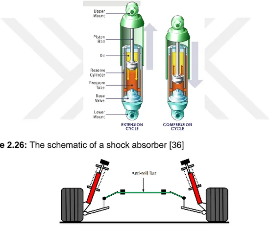
Shock absorbers also differ among themselves. For instance; the substance inside of the tube which helps in preventing the spring from oscillating can be hydraulic or gas. Figure 2.26 shows the schematic of a shock absorber.
Anti – Roll Bar: Anti - roll bar which is also known as anti - sway bar is another important component in suspension systems. This component acts as a stabilizer. They are necessary in a suspension system to prevent the vehicle to roll during a sharp turn. Whilst turning a corner or making a sharp turn the vehicle body will intend to roll which will put more pressure on one of the suspensions on the right and left. The anti - roll bar will transfer some of this energy to the less pressurized suspension in order to keep the car from rolling over [35]. In Figure 2.27; an example for anti – roll bar / anti - sway bar is given.
Figure 2.26: The schematic of a shock absorber [36]
Figure 2.27: An example of an anti - roll bar in a suspension system [37]
In addition to these components; suspension systems comprise further linkage elements such as bushings, ball joints etc.
2.3.2.2 Suspension System types
Suspension system type chosen for a vehicle has a big effect on the ride comfort and safety. The selection of the suspension system is based on parameters such as safety, weight, cost, design etc. Although the function of a suspension system is same for all different types; some suspension types offer more advantageous than others.
2.3.2.2.1 Solid Axle Beam Suspension
Solid axle beam suspension is actually a non-independent suspension system which was explained earlier. It is one of the oldest examples of a suspension system. Nowadays it is usually preferred as the suspension system for rear side of the vehicles. They are also used in situations where heavy loads are carried.
This type of suspension system is in layman terms a rigid axle with wheels on both sides. And on these beam; a combination of shock absorbers and springs are used. Solid axle beam suspension system may comprise leaf springs or coil springs which are more advantageous. Leaf springs are not as efficient as coil springs in regards to their dampening abilities. So a solid axle suspension with coil springs would be able to absorb the vibrations more efficiently. Examples for a solid axle beam suspension with leaf and coil springs are given in Figure 2.28 – 29 below.
Since this type of suspension systems share a rigid beam and therefore are non – independent from each other; the movement of one wheel would affect the other one as well. Due to that; this suspension type offers less ride quality. However they offer good load carrying capabilities and they are relatively cheaper and simpler. [38]
Figure 2.28: Solid axle beam suspension with leaf springs [38]
2.3.2.2.2 Torsion Bar Suspension
Another type of suspension system used is the torsion bar suspension system. Torsion bar is basically a metal rod. These metal rod acts as a spring in order to absorb the vibrations. The torsion bar is fixed at one end and it is attached to the vehicle at that end while the other end of the bar is connected to the suspension system. Suspension systems that uses torsion bars are used in some light vehicles while some defence vehicles are also equipped with torsion bar suspensions. Torsion bar suspension systems are relatively simpler and they require less space which makes it possible to have more space for major components such as engine and so on.
The working principle of the torsion bar suspension system is based on the twisting movement of the torsion bar at the end that is connected to the suspension. When a wheel moves vertically due to uneven terrain; the torsion bar will be twisted. Since the other end is fixed and cannot move in anyway; the bar tries to resist this torque motion and return to its untwisted state by pushing the wheel downwards. [39]
Torsion bars must be able to resist high amount torques in order to function properly as a suspension system. Therefore torsion bars must be made of materials that possess high torsional yield properties. There are certain important parameters which defines the properties of the torsion bar. These parameters include selected material, bar length, area of the cross section [40]. Torsion bar suspension system example is given in Figure 2.30.
Figure 2.30: A torsion bar suspension system example [41] 2.3.2.2.3 Air Spring Suspension
Springs along with shock absorbers are the most of vital components in suspension systems as stated before. In addition to the previous spring types that were explained such as leaf and coil springs; another spring type which also is the name of another suspension system is air springs and as the name suggests they are filled with compressed air. Whenever there is a vertical movement of the wheels; the air gets more compressed and in doing so absorbs the incoming vibrations. This suspension system was and is still widely used by buses which are heavy vehicles [42]. An example is shown in Figure 2.31.
Air spring suspensions do not comprise of metal springs in contrast to other suspension system types. It comprise airbags which are filled with compressed air. Instead of metal springs; there are 4 airbags which are made rubber and the compressed air is used to absorb the vibrations. The amount of air inside the airbags can be adjusted with the help of a compressor built in to the vehicle. This ability to change the air amount allows the driver to adjust the suspension system to optimum conditions. Due to this adjustability; air springs may offer a more comfortable ride as the suspension can be tuned instantly whenever the driving conditions were changed. However this type of suspension is more complex, more prone to failures and it would also be more costly as the instalment costs are higher. [43]
Figure 2.31: Air suspension system example [44] 2.3.2.2.3 Double Wishbone Suspension
As mentioned several times; there are different suspension system types and all of them have their uses along with their advantages and disadvantages. The next suspension system type is double wishbone suspension and it is one of the most popularly used front suspension system for many passenger vehicles along with the MacPherson suspension.
Double wishbone suspension is a popular front suspension and it is also known as short long arm suspension or double A arm suspension. The reason for this is the fact that a double wishbone suspension has two control arms and their sizes are different from each other [45]. An illustration of a double wishbone suspension system is given in Figure 2.32 below.
Figure 2.32: Illustration of a double wishbone suspension [46]
A double wishbone suspension comprises a coil spring placed around a shock absorber. Furthermore there are two control arms which are upper control arm and lower control arm. These control arms are called wishbones due to their shapes and
they are attached to the wheel hub at one end and to the chassis on the other end. The lower control arm is larger than the upper control arm and this difference is the reason behind a major advantage of double wishbone suspensions. Double wishbone suspension systems are the better choice compared to the other popular suspension type MacPherson suspension regarding the parameters such camber, kingpin inclination, scrub radius etc. which are important factors about steering. The size difference between the control arms allow double wishbone suspensions to offer better control of these parameters. [47]
Figure 2.33 below illustrates the size differences of the control arms. The vertical movement of the wheels are much smoother as a result of having two control arms and the size difference of the control arms.
Figure 2.33: Double wishbone suspension system illustration [48]
When a car with a double wishbone suspension system goes over a bump; the corresponding wheel move vertically. Since the control arms are attached to the wheel; they would move accordingly and help controlling the vehicle position. As a result of this movement; the coil spring would compress and absorb the vibrations occurring because of the irregularities on the road surface. The compression of the spring would lead to the movement of the piston which is placed in the shock absorber. Hence the hydraulic fluid or gas inside the shock absorber would resist against the piston; the movement of the piston would be quite slow as the fluid or gas can only pass through small channels on the valve which is placed at the bottom of the piston. Therefore; the movement of the piston would transform the energy that is absorbed by the spring into heat and transfer it to the fluid or gas. These actions would result in a passenger cabin which is secluded and not affected by the vibrations.
As stated before; double wishbone suspension system is widely used in passenger cars. It is especially common for high segment vehicles and SUVs due to its good features [48]. In Figure 2.34 a photo of an Audi R8 vehicle with a double wishbone suspension is given. In this image; other components such as steering axis, brake disc etc. can be seen as well.
Figure 2.34: Audi R8 with a double wishbone suspension system [49] 2.3.2.2.4 MacPherson Strut Suspension
MacPherson strut suspension system is a front suspension system used widely in many modern passenger cars today. It is the most popular suspension system used along with double wishbone suspension system.
MacPherson strut suspension was developed by the American automotive engineer Earle S. MacPherson in the 1940s. It was during his time at Ford Motor Company where he developed the suspension system that is known by his name. MacPherson strut suspension was used for the first in Ford Vedette in 1949 [50]. Since then it gained a lot of popularity and an example of it is shown in Figure 2.35.
MacPherson strut suspension system and double wishbone suspension system are similar to each other. The main difference is the number of control arms used. MacPherson strut suspension system comprises only one control arm which is located at the bottom whereas double wishbone suspension has two control arms respectively upper control arm and a lower control arm. Other than a control arm; MacPherson strut suspension comprises a shock absorber, a coil spring, spring seats and some linkage elements such as ball joints. The lower control arm is attached to the wheel hub at one end and to the vehicle frame on the other end similar to double wishbone suspension. It was stated that having two control arms offer more control over certain parameters such as camber angle. Since MacPherson has only one; double wishbone suspension offers better control over these parameters. [51]
MacPherson’s suspension system is known as MacPherson strut which is actually a name of one of the components. MacPherson strut is basically the combination of a shock absorber and a coil spring. MacPherson strut is a metal rod that acts like a second control arm and is attached to the vehicle from the top while the bottom is attached to the wheel hub. MacPherson strut is also a structural component that helps carrying load. This component has a piston and a hydraulic fluid inside of it which is used to prevent the oscillation of the spring. The strut also has spring seats where the coil spring is placed. So a MacPherson strut can be defined as a component comprising a strut housing which carries the coil spring which is used to absorb the excitations and surrounds the damping unit to transfer the energy absorbed by the spring [45]. An example of a strut is shown in Figure 2.36 below.
Figure 2.36: A strut example [52]
As the MacPherson strut is attached to wheel hub; when a wheel moves upwards the MacPherson strut moves upwards as well. The movement of the strut housing would lead to the compression of the spring and in the meantime the piston inside the strut housing which is attached to the vehicle body from the top would come in contact with the fluid or the gas inside the strut housing. The piston itself is a metal rod with a valve with channels and it attached to the vehicle frame from the top so it does not move. However the strut hosing moves upwards and downwards in accordance with the wheels and this leads to the fluid inside to pass through the valve and in doing so slow down the movement of the spring in order to prevent from oscillation and bouncing. Figure 2.37 below shows a Audi TTRS with a MacPherson strut suspension.
Figure 2.37: Audi TTRS with MacPherson strut type suspension [49]
MacPherson strut suspension’s biggest advantage is its simplicity. The fact that the major components which are the shock absorber and the coil spring are brought
together into one component is one of the main reasons for the popularity of this suspension system. All other components such as dustboot, upper mount and strut bearing which is the combination of the upper spring seat, the metal bearing and the upper cap are all assembled together. A MacPherson strut suspension could easily be assembled separately and then installed to the vehicle with everything ready. Attaching the bottom of the strut housing to the wheel hub and attaching the top side to the vehicle frame is all that is needed. A comparison between the most popular suspension systems which are double wishbone suspension and MacPherson strut suspension system is given shortly [23]. Another illustration of the MacPherson strut suspension is shown is Figure 2.38 and all major components are named.
![Figure 2.8: Crystalline and amorphous structure types [4]](https://thumb-eu.123doks.com/thumbv2/9libnet/5468081.105727/22.892.188.693.551.824/figure-crystalline-amorphous-structure-types.webp)
![Figure 2.9: Illustration of plastic reinforcements [1]](https://thumb-eu.123doks.com/thumbv2/9libnet/5468081.105727/24.892.152.671.202.587/figure-illustration-of-plastic-reinforcements.webp)
![Figure 2.10: Plastic production methods [1]](https://thumb-eu.123doks.com/thumbv2/9libnet/5468081.105727/25.892.114.802.357.972/figure-plastic-production-methods.webp)
![Figure 2.13: Injection unit of an injection moulding machine [19]](https://thumb-eu.123doks.com/thumbv2/9libnet/5468081.105727/27.892.163.726.195.490/figure-injection-unit-injection-moulding-machine.webp)
![Figure 2.16: Suspension system in an automobile [23]](https://thumb-eu.123doks.com/thumbv2/9libnet/5468081.105727/29.892.161.703.374.891/figure-suspension-system-in-an-automobile.webp)
![Figure 2.20: Simple illustration of a vehicle suspension system [29]](https://thumb-eu.123doks.com/thumbv2/9libnet/5468081.105727/32.892.147.704.437.720/figure-simple-illustration-vehicle-suspension.webp)
![Figure 2.22: Illustration of leaf springs in suspension systems [32]](https://thumb-eu.123doks.com/thumbv2/9libnet/5468081.105727/33.892.140.670.370.544/figure-illustration-leaf-springs-suspension-systems.webp)
![Figure 2.28: Solid axle beam suspension with leaf springs [38]](https://thumb-eu.123doks.com/thumbv2/9libnet/5468081.105727/36.892.193.688.551.779/figure-solid-axle-beam-suspension-leaf-springs.webp)
![Figure 2.30: A torsion bar suspension system example [41]](https://thumb-eu.123doks.com/thumbv2/9libnet/5468081.105727/37.892.223.676.629.861/figure-a-torsion-bar-suspension-system-example.webp)
