CONTEXTPROXY: A LOCATION-AWARE HTTP PROXY
SERVER TO SUPPORT WEB BASED CONTEXT-AWARE
SERVICES AND APPLICATIONS
A THESIS
SUBMITTED TO THE DEPARTMENT OF COMPUTER ENGINEERING AND THE INSTITUTE OF ENGINEERING AND SCIENCE
OF BILKENT UNIVERSITY
IN PARTIAL FULFILLMENT OF THE REQUIREMENTS FOR THE DEGREE OF
MASTER OF SCIENCE
By
Alper R. Uluçınar
January, 2005
ii
I certify that I have read this thesis and that in my opinion it is fully adequate, in scope and in quality, as a thesis for the degree of Master of Science.
__________________________________ Asst. Prof. Dr. David Davenport (Advisor)
I certify that I have read this thesis and that in my opinion it is fully adequate, in scope and in quality, as a thesis for the degree of Master of Science.
__________________________ Asst. Prof. Dr. Ali Aydın Selçuk
I certify that I have read this thesis and that in my opinion it is fully adequate, in scope and in quality, as a thesis for the degree of Master of Science.
____________________________ Asst. Prof. Dr. İbrahim Körpeoğlu
Approved for the Institute of Engineering and Science:
____________________ Prof. Dr. Mehmet Baray Director of the Institute
iii
ABSTRACT
CONTEXTPROXY: A LOCATION-AWARE HTTP PROXY
SERVER TO SUPPORT WEB BASED CONTEXT-AWARE
SERVICES AND APPLICATIONS
Alper R. UluçınarM.S. in Computer Engineering Supervisor: Asst. Prof. Dr. David Davenport
January, 2005
The pervasion of computing in our physical world promises more than the ubiquitous availability of computing resources; totally new and exciting interaction schemes are to be explored. Context-awareness, one of the most important aspects of ubiquitous computing, enables applications that make use of their users’ context to provide dynamically adapting information and services to their users or to other applications. Although the technological infrastructure to support ubiquitous and context-aware applications is being deployed rapidly, the standards and the best practices for the interactions of various components in a context-aware application are still missing. In our work we have developed a location-aware HTTP proxy server, called ContextProxy that runs on the popular Symbian platform. ContextProxy acts as a standard HTTP proxy server from the client application’s perspective but it augments the service request of the client with the available location information while submitting the request to the service provider. This allows the existing nomadic applications to immediately become location-aware if they can be configured to make use of a standard HTTP proxy which is a common scheme for web based applications. And also it is possible to write new nomadic applications without considering the context-awareness aspect at the service requestor level. The contextual information added by ContextProxy can then be utilized by the service provider to dynamically adapt its services according to the service requestor’s context.
iv
ÖZET
CONTEXTPROXY: AĞ TABANLI
BAĞLAMDAN-HABERDAR HİZMETLERİ VE UYGULAMALARI
DESTEKLEMEK İÇİN YERDEN-HABERDAR HTTP PROXY
SUNUCUSU
Alper R. Uluçınar
Bilgisayar Mühendisliği, Yüksek Lisans Tez Yöneticisi: Asst. Prof. Dr. David Davenport
Ocak, 2005
Gündelik yașamımıza hızla giren bilgi ișleme ve haberleșme yeteneğine sahip tașınabilir cihazlar, bizlere sadece her an her yerde hesaplama yapabilme ve haberleșebilmeden daha fazlasını vaat etmektedirler. Hızla gelișen ve gün geçtikçe yașamımıza daha derinden nüfuz eden bu altyapı bileșenleri tamamen yeni etkileșim yöntemlerini ve uygulamaları mümkün hale getirmișlerdir. Bu yeni uygulama ve hizmet sağlama yaklașımlarından bir tanesi de bağlamdan-haberdar uygulamalardır. Bağlamdan-haberdar uygulamalar, kullanıcılarına sağladıkları hizmetleri ve bilgiyi kullanıcılarının içlerinde bulundukları bağlama göre devingen olarak uyarlayabilen uygulamalardır. Bağlamdan-haberdar uygulamaları desteklemek için gerekli altyapısal bileșenlerin hızla yaygınlașmalarına karșın bu uygulamalarda rol alacak çeșitli bileșenlerin birbirleriyle etkileșimlerinde kullanılacak kabul görmüș yaklașımlar ve standartlar henüz mevcut değildir. Bu çalıșmamızda ContextProxy adını verdiğimiz yaygın olarak kullanılan Symbian düzleminde çalıșan yerden-haberdar bir HTTP proxy sunucusu geliștirdik. ContextProxy’nin istemci uygulama tarafından standart bir HTTP proxy sunucusu olarak algılanmasına karșın esas ișlevi, istemciye ait istekleri hizmet sağlayıcıya aktarırken kullanıcının bağlamından çıkardığı yer bilgisiyle zenginleștirmesidir. Böylelikle halihazırda kullanılmakta olan uygulamalar veya yeni geliștirilecek olanlar standart bir HTTP proxy sunucusu kullanmaya ayarlanabilir oldukları sürece yerden-haberdar hale gelebilmektedirler.
v
Acknowledgements
I gratefully thank my supervisor Asst. Prof. Dr. David Davenport for his invaluable supervision and guidance. He has encouraged me all the way and without his encouragement and guidance, this work would have never been completed.
I would also like to address my special thanks to my thesis committee members Asst. Prof. Dr. Ali Aydın Selçuk and Asst. Prof. Dr. İbrahim Körpeoğlu for kindly accepting to review my thesis and for guiding me with their invaluable comments.
And finally I would like to express my gratitude to my mother and to my father. Throughout this work I once again appreciated the value of having a family.
vi
Contents
1. Introduction...1
1.1 Definition of Context and Context-aware computing...2
1.1.1 Definition of Context...2
1.1.2 Definition of Context-Aware Computing...4
1.2 Sensor Technologies ...4
1.2.1 Infrared ...4
1.2.2 Bluetooth ...9
1.2.2.1 Bluetooth Stack ...10
1.2.2.2 Masters, Slaves, Slots and Frequency Hoping ...12
1.2.2.3 Piconets and Scatternets ...13
1.2.2.4 Overview of the Bluetooth Profiles...14
1.2.2.5 The Dialup Networking Profile...15
1.2.3 Global Positioning System ...17
1.2.4 GSM and GPRS...19
1.2.5 Wireless Local Area Networks...20
1.2.6 Hybrid Technologies ...21
vii
2.1 Motivations ...23
2.2 Usage Scenarios ...25
2.2.1 Emergency Requestor with Active Human Intervention...25
2.2.2 Location Information Point and Nearest Printer Service ...27
2.2.3 Persistent Messages Left to a Place...29
2.3 Design and Implementation ...31
2.3.1 Main Design Considerations ...31
2.3.2 Definitions of Architectural Components ...32
2.3.2.1 Service Client ...32
2.3.2.2 ContextProxy...33
2.3.2.3 Remote Proxy...34
2.3.2.4 Context Server...34
2.3.3 Extracting Location Information from User’s Context ...34
2.3.4 Why Symbian? ...36
2.3.5 Using ContextProxy in Centralized Architectures ...37
2.3.5.1 Configuring the Remote Proxy ...37
2.3.5.2 Configuring the Local Bind Port...38
2.3.5.3 Configuring the Context Server ...38
2.3.5.4 Configuring the Internet Access Provider...39
2.3.5.5 Message Traffic in the Centralized Architecture ...40
2.3.6 Using ContextProxy in Decentralized Architectures ...43
2.3.6.1 Configuring the Bluetooth Access Point...45
2.3.6.2 Setting up a Bluetooth Access Point on Windows XP Systems ...46
viii
List of Figures
Figure 1-1. IR Transducer Module...6
Figure 1-2. The ORL Active Badge...7
Figure 1-3. ORL Badge Sensor and Sensor Network ...8
Figure 1-4. The MessagePad and the IR positioning prototype...9
Figure 1-5. The Bluetooth Stack ...11
Figure 1-6. Piconets with different modes of operation...13
Figure 1-7. Bluetooth DUN...16
Figure 1-8. DUN and the Bluetooth Stack ...17
Figure 1-9. The ORL mobile transmitter ...21
Figure 2-1. Emergency Requestor...26
Figure 2-2. Local Information Server and Printing Service...28
Figure 2-3. Persistent Messages Left to a Place...30
Figure 2-4. Configuring the remote proxy's IP address ...37
Figure 2-5. Configuring the remote proxy's TCP port ...37
Figure 2-6. Configuring the local TCP bind port...38
ix
Figure 2-8. Configuring the context server’s TCP port ...39
Figure 2-9. Configuring the IAP ...40
Figure 2-10. Message traffic in a centralized architecture - Content request ...41
Figure 2-11. Message traffic in a centralized architecture - Virtual host request ...42
Figure 2-12. Message traffic in a decentralized architecture - Virtual host request ...44
Figure 2-13. Instructing ContextProxy to connect to a Bluetooth access point...45
Figure 2-14. Selecting the access point from the list of discovered devices...45
1
Chapter 1
Introduction
Although the necessary technological infrastructure to support context-aware applications is being deployed rapidly, applications themselves are still few. Today’s concept of a smart phone is a good example for this. According to a recent strategic market research report [1], the shipments of feature rich smart mobile devices reached 9.8 millions in 2003. And according to the same report the number of devices featuring applications platforms such as Java, BREW, and GVM reached 115 million units in 2003. The report suggests that in 2008, 89 million units of high-end smart devices will be sold and 627 million units of lower-end devices with one or more of these platforms will be sold. We have more and more computing and communications power with us in our daily lives but still we don’t know how to make real use of it. For instance the standard applications shipped with the popular Nokia Series 60 smart phone platform are:
• Calendar application
• Contacts application
• Text and multimedia and email messaging applications
• WAP and HTML browsers
• Digital imaging applications to support the onboard camera
• Games and some other similar PIM (personal information management) and multimedia applications.
As this list of applications suggests, these smart mobile platforms are treated just as “desktops” that you can carry along with yourself. However the availability of computing and communications infrastructure in our daily lives promises much more than that. We can make use of this infrastructure to support ourselves in various contexts that we run into by running context-aware applications on these mobile smart devices. For instance we can develop phone software which automatically switches to a silent profile after sensing the presence of other nearby people. Or we can make use of the location information of a nomadic user to give him details of the place’s history or to offer him a printing service which automatically chooses the nearest printer available. The time has come to develop applications that do not just assume what context their users are in. Applications of the new era should actively collect information about their users’ contexts and accordingly adapt their services to accommodate their users’ changing needs.
1.1 Definition of Context and Context-aware computing
1.1.1 Definition of Context
Context is defined as “the whole situation, background, or environment relevant to a particular event, personality, creation, etc.” in Webster’s New World Dictionary [2]. Giving a formal definition for context is not as easy as it first seems because every existence or every happening is bound to some kind of context and so giving a clear, non-self-referencing definition of what a context is a serious problem in itself. In a computing environment, we have many uses for the word context such as context-aware computing, context sensitive help, and so on. Many researchers in computer science have attempted to define the notion of context using synonyms and/or enumerations (examples). Schilit and Theimer [3] define context as the location, the identities of the
nearby people and other objects of interest and changes to these entities. In another study Schilit et al. point to three main classes of context in a computing environment [4]:
• Computing context which constitutes of the relevant hardware and software infrastructure such as the workstations, network infrastructure or the operating system,
• User context which is determined by the various aspects related to the entities which carry the operational role of being a user in the system, such as the
location of the user, identities of the nearby (‘relevant’) entities, or what the user aims to do,
• Physical context which constitutes of the various physical aspects of the surrounding physical world such as the temperature, lighting level, time of the day and so on.
Schmidt et al. define context as “knowledge about the user’s and the IT device’s state including surroundings, situation and to a less extent, location” [5]. All these definitions are partly based on enumerations of different sub-contexts such as the ‘location’, the ‘identities of the nearby entities’ and are based partly on synonyms such as ‘situation’, ‘state’ and so on. Some other researchers have tried to give more general definitions for context by avoiding enumerations. For instance Dey defines context as [5] “any information that can be used to characterize the situation of an entity. An entity is a person, a place or an object that is considered relevant to the interaction between a user and an application, including the user and the applications themselves”. And likewise Pascoe defines context to be the subset of physical and conceptual states of interest to a particular entity [3]. Although these definitions are inherently more general since specific concrete sub-contexts are not enumerated, it becomes vaguer to apply these definitions in deciding whether a piece of information is part of the context or not. In our work we have not attempted to give a better definition for context but instead we have investigated the ways of making specific contextual information (such as the location information) available to the services and applications used in everyday life so that they may adapt themselves dynamically and appropriately according to the changing contexts’ of their users.
1.1.2 Definition of Context-Aware Computing
Context-aware computing is a mobile computing paradigm [5] in which applications make use of contextual information such as the location of the user of the application, locations of other entities related with the application (such as the location of the nearest display), the time of the day, identities of nearby people, and so on. Context-aware applications dynamically adapt themselves and provide services and/or information according to the context they are (ideally their users are) in.
For a context-aware application, wide availability is a key concern, because the users of the application will in most circumstances be nomadic. The context-aware application will have to use different infrastructures (different data networks, different sensors, etc.) to provide its services. In order to support nomadic users without much configuration effort on the user side, wireless data networks and wireless sensors are preferred in context-aware applications.
In the following sections we will discuss various sensor and wireless networking technologies that can be the underlying infrastructure for context-aware applications with special emphasis on Bluetooth and GSM, since these are the two key technologies that we have employed in our applications. For each technology we will reference the applications that have employed that technology and we are aware of.
1.2 Sensor Technologies
1.2.1 Infrared
Since infrared (IR) is in use for quite a long time in the industry, it has proved itself to be a reliable and cheap means of communication. IR is widely in use in the consumer
electronics industry for purposes such as the remote controlling of electronic devices or for wireless data communications in cellular phones. The main standards body behind IR is IrDA (Infrared Data Association). IrDA is a non-profit organization whose primary goal is to develop globally adopted specifications for infrared wireless communication [6]. It embodies various special interest groups responsible for defining new specifications for tasks such as making infrared wireless payments at POS terminals (IrFM), or transferring digital content at speeds up to 100Mb/s (IrBurst). IrDA also embodies committees such as the Architectural Council, the Marketing Committee, the Technical Committee, and the Test and Interoperability Committee. The main objective of the Architectural Council is to provide architectural support in the early definitions of new specifications for ensuring compatibility and consistency with earlier specifications. The Marketing Committee handles marketing issues related with the IR technology. The Technical Committee resolves technical issues encountered during the specification development process. The Test and Interoperability Committee provides testing and certification services for the implementations of the IrDA specifications to ensure compliance and interoperability between various vendors.
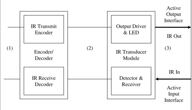
Although the IrDA Serial Infrared Physical Layer Specification [7] only defines the serially encoded output and input IR signals, a simplified block diagram for a typical end of a serial IR link is as follows:
Figure 1-1. IR Transducer Module
In this diagram the electrical signals at region (1) represent the serial data that’s to be communicated over the IR link and passed to the transducer module for transmission or data that’s been received by the transducer. The electrical signals at region (2) are the electrical representations for the optical IR signals at region (3) and are interpreted into optical signals by the output driver and the IR LED or are generated by the detector and the receiver upon receiving the optical signals. The specification defines a serial infrared link to be of length between 0 and at least 1 meter but common implementations provide wireless infrared signal transmission over 3-6 meters.
The Olivetti Research Center’s (ORL) Active Badge Location System [8] uses an infrared tagging device to track the location of people in a building. The tagging device is called as an Active Badge and is worn on the outside of clothing in order not to prevent the IR signals emitted by the device from reaching the sensor network. The device emits a unique identifier revealing the identity of the person who is carrying it
IR Transmit Encoder Encoder/ Decoder IR Receive Decoder Output Driver & LED IR Transducer Module Detector & Receiver Active Output Interface IR Out Active Input Interface IR In (1) (2) (3)
encoded as an infrared signal for an interval of about 100 ms at every 15 seconds. The schematic diagram of an active badge is as follows:
Figure 1-2. The ORL Active Badge [8]
The badge is packaged in a 55x55x7 mm box and weights 40 g. The relatively long delay of 15 s between emissions and the short emission interval of 100 ms were chosen to lower the average current consumption of the device and to decrease the probability that two active badges in the same room emit their ids simultaneously. These two parameters assume that people in a building generally move slowly. The signals emitted by the active badges reach a sensor network providing thorough coverage in the building. The schematic diagram of a badge sensor and the network topology for the sensor network is shown below:
IR Emitter Driver PAL FSM Commercial Remote Control Encoder Test Button 15 Second Astable Light Dependent Timing Circuit Unique IR Signal
Figure 1-3. ORL Badge Sensor and Sensor Network [8]
The data collected by the sensor network is processed by a central server. Up to 128 sensors are connected to the central server through the RS232 port of a standard workstation. The central server and the workstations communicate using conventional network protocols. Each sensor is connected to a 4-wire network. Two of these wires carry the network power supply. One wire is used to serially address sensor nodes in a 7-bit address space. And the other wire carries serial data (the sensed badge identifiers) back to the workstation. Each sensor node utilizes a FIFO buffer of length 20 badge identifiers so that a sensed badge identifier will not be lost if a new badge is sensed before the sensor node is polled.
The Future Computing Environments (FCE) group within the College of Computing and the Graphics, Visualization and Usability (GVU) center at Georgia Tech developed another location-aware application called the Cyberguide [9]. Cyberguide has many prototypes and one prototype of it which is to be used indoors, utilizes infrared technology to collect location information from surrounding beacons. The positioning component of this Cyberguide prototype is based on using commercial TV remote
IR Signal Received DETECTOR DECODER FIFO NETWORK IF ADDRESS 4-WIRE NETWORK SENSOR STATION WORKSTATION WORKSTATION Badge Network Sensor Station ETHERNET
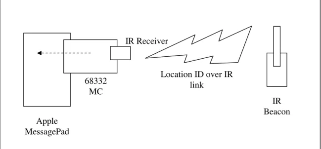
controls as infrared beacons. These beacons are mounted on the walls of the GVU center and each beacon periodically emits an infrared signal which carries the unique identifier of the location of the beacon. The tourist visiting the GVU center carries an Apple MessagePad running the Cyberguide application on it. In order to receive the location identifiers emitted by the infrared beacons, an infrared receiver interfaced by a Motorola 68332 microcontroller is plugged on each MessagePad. When a location identifier is detected by the receiver, the microcontroller serializes the identifier and transmits the serialized identifier to the MessagePad using the serial port. This location information is then utilized by the Cyberguide application running on the MessagePad:
Figure 1-4. The MessagePad and the IR positioning prototype
1.2.2 Bluetooth
Bluetooth is a low cost, low power, short range radio technology, originally developed as a cable replacement technology to connect devices such as mobile phones, headsets and portable computers. Bluetooth has created the notion of a Personal Area Network (PAN). Bluetooth technology development was started in 1994 by Ericsson and Version 1.0 of the Bluetooth specification came out in 1999. Current version of the core Bluetooth specification is 1.2 although most Bluetooth devices currently available in the
Apple MessagePad 68332 MC IR Receiver IR Beacon Location ID over IR link
market support version 1.1. The Bluetooth SIG was founded in 1998 and the current list of core promoter companies include Ericsson Mobile Communications AB., Intel Corp., IBM Corp., Toshiba Corp., Nokia Mobile Phones, Microsoft, Lucent, 3COM and Motorola.
1.2.2.1 Bluetooth Stack
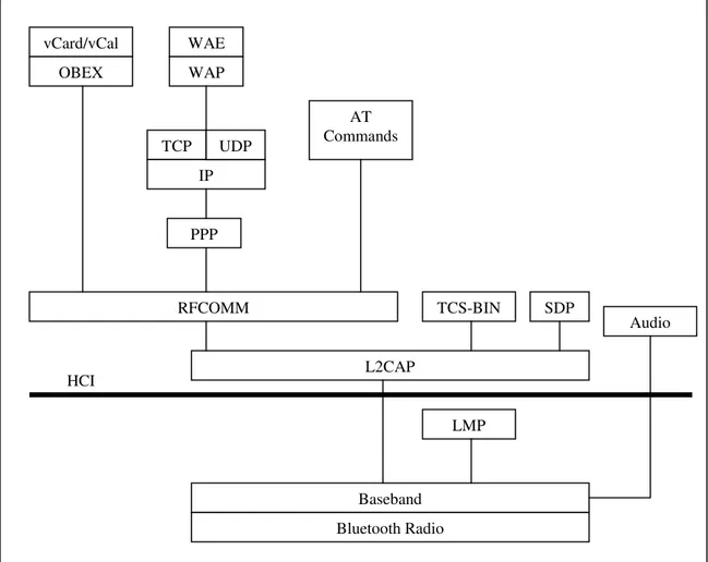
Bluetooth specification aims to allow devices from different manufacturers to work with one another. Bluetooth specification does not only cover a radio system but also defines a software stack to enable applications to find other Bluetooth devices in the vicinity, discover the services they offer, and use those services. The Bluetooth stack is defined as a series of layers:
• At the bottom of the stack, the radio modulates and demodulates data for transmission and reception on air.
• The baseband and link controller controls the physical links via the radio, assembling packets and controlling frequency hopping. A Bluetooth device changes the radio frequency at which it is transmitting 1600 times a second.
• The link manager controls and configures links to other devices.
• The Host Controller Interface handles communications between a separate host and a Bluetooth module.
• Logical Link Control and Adaptation multiplexes data from higher layers, and converts between different packet sizes.
• RFCOMM provides RS232 serial line emulation.
• WAP and OBEX provide interfaces to the higher layer parts of other communications protocols.
• SDP (Service Discovery Protocol) lets Bluetooth devices discover what services other Bluetooth devices offer.
The Bluetooth stack can be visualized as follows:
Figure 1-5. The Bluetooth Stack
Also Bluetooth SIG defines Bluetooth profiles, which give guidelines on how applications should use the Bluetooth protocol stack. These Bluetooth profiles provide interoperability among different manufacturers and products.
vCard/vCal OBEX WAE WAP TCP IP UDP PPP AT Commands RFCOMM L2CAP TCS-BIN SDP Audio Baseband Bluetooth Radio LMP HCI
1.2.2.2 Masters, Slaves, Slots and Frequency Hoping
A Bluetooth device operates in one of the two modes: as a master or as a slave. The master defines the frequency hoping sequence. Slaves that connect to the master device synchronize with the master device's clock and use the master device's unique Bluetooth address together with the timing information to calculate the frequency hopping sequence. This way all slave devices that connect to a master device become synchronized with the master device's frequency hopping sequence. The master device also controls when devices are allowed to transmit data. The master allows slaves to transmit by allocating slots for voice traffic or data traffic. In data traffic slots, the slaves are only allowed to transmit when replying to a transmission to them by the master. In voice traffic slots, slaves are required to transmit regularly in reserved slots for them whether or not they are replying to the master. The master controls how the total available bandwidth is divided among the slaves by deciding when and how often to communicate with each slave. The number of time slots each slave gets depends on its data transfer requirements.
In order to support both time critical voice data and time insensitive packet data, Bluetooth specification defines two different types of links between Bluetooth devices. These are SCO (synchronous connection oriented) links for voice communication and ACL (asynchronous connectionless) links for data communication. The largest ACL packet defined by the specification is five time slots long and can carry 2858 bits of data together with the ACL packet headers. If it is assumed that such an ACL packet is replied with a single slot length ACL packet then the maximum baseband data rate in one direction is about (1600/6) * 2858 = 762 kb/s. But the other direction will only transmit with an available capacity of about 58 kb/s. If the overhead added by the higher layer protocols is also considered, the maximum available bandwidth decreases to about 650 kb/s on average. For voice traffic (the SCO link) the available bandwidth is 64 kb/s.
1.2.2.3 Piconets and Scatternets
Two or more units sharing the same channel form a piconet. As explained above one Bluetooth unit acts as the master of the piconet, whereas the other unit (or units) acts as slave(s). Up to seven slaves can be active in the piconet. In addition many more slaves can remain locked to the master in a so-called parked state. These parked slaves cannot be active on the channel, but remain synchronized to the master. Both for active and parked slaves, access to the channel is controlled by the master device.
Figure 1-6. (a) Piconet with a single slave operation. (b) Piconet with multi-slave operation. (c) Scatternet operation. [10]
Multiple piconets being connected through slaves form scatternets. Each piconet can only have a single master (so a master of a piconet cannot be the master of another separate piconet, by definition these devices are in the same piconet). However slaves can participate in different piconets on a time-division multiplex basis. In addition a
(a) (b) (c)
Master
master in one piconet can be a slave in another piconet. The piconets constituting a scatternet will not be frequency synchronized. Each piconet will have its own hopping sequence.
1.2.2.4 Overview of the Bluetooth Profiles
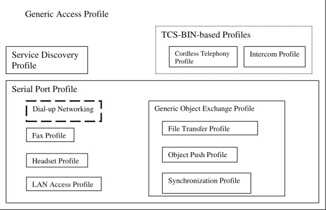
Bluetooth profiles give guidelines to applications about how they should make use of the Bluetooth protocol stack. Some profiles are defined on top of other profiles (i.e. the dial-up networking profile makes use of the serial port profile which in turn makes use of the generic access profile). Some profiles like the generic access profile or the serial port profile are implemented as part the core stack. Bluetooth profiles ensure that the Bluetooth enabled applications developed by independent developers will work on any device that conforms to the Bluetooth specification. At a minimum, each profile specification contains guidelines on the following topics [11]:
• Dependencies on other profiles: Every Bluetooth profile depends on the functionality provided by the Generic Access Profile (GAP) and some profiles also depend on the functionalities provided by the other higher level profiles (i.e. the Dialup Networking Profile depends on GAP and the Serial Port Profile).
• Suggested GUI approaches: Each profile specification also suggests GUI formats for Bluetooth profile implementers to ensure a consistent Bluetooth end-user experience.
• Information about the configuration of the parts of the Bluetooth protocol stack used by the profile: To provide its functionality each profile makes use of the parts of the Bluetooth protocol stack with some defined options and parameters. For instance this may include a service record in the SDP layer. The profile specification should include every detail about the required configuration of the protocol stack so that it can be implemented in a consistent way.
Some of the profiles defined by the Bluetooth SIG consist of: Human Interface Device (HID) Profile, Generic Object Exchange Profile (GOEP), Serial Port Profile (SPP), Dialup Networking (DUN) Profile, Cordless Telephony Profile (CTP), Personal Area Networking (PAN) Profile, File Transfer Profile (FTP, specified as part of the PAN profile).
The generic access profile defines a consistent way to establish a baseband link between two Bluetooth devices. In addition the GAP defines the features common to all Bluetooth devices such as procedures for discovering and being discovered by other Bluetooth devices and the basic UI terminology. All other profiles are based on the GAP. This allows other profiles to be specified more easily since the basic definitions and the procedures are provided readily by the GAP. Also having GAP common to all profiles at the lowest level of the profile hierarchy ensures better interoperability between Bluetooth devices and applications.
The serial port profile defines RS232 serial cable emulation for Bluetooth devices. The SPP provides ordinary serial communication ports operating over Bluetooth to higher level profiles and other applications and so with the SPP, legacy applications based on serial communication can exchange data between Bluetooth devices. The SPP makes use of the RFCOMM protocol.
In the following section we mention about the Dialup Networking (DUN) profile in detail because some parts of our work are based on this profile.
1.2.2.5 The Dialup Networking Profile
The dialup networking profile defines the protocols and procedures that shall be used by devices implementing the usage model called "Internet Bridge". The most common
examples of such devices are modems and cellular phones. The scenarios covered by this profile are:
• Usage of a cellular phone or modem by a computer as a wireless modem for connecting to a dial-up internet access server, or using other dial-up services.
• Usage of a cellular phone or modem by a computer to receive data calls.
The DUN profile makes use of the Serial Port Profile (SPP) and Generic Access Profile (GAP) as shown in the following figure:
Figure 1-7. Bluetooth DUN
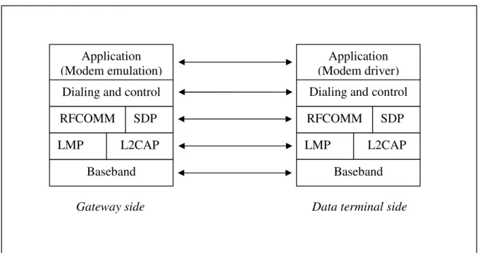
In this figure each profile contained in another profile’s box makes use of the containing profile. The DUN Profile makes use of the following Bluetooth stack layers:
Generic Access Profile
Service Discovery Profile
TCS-BIN-based Profiles Cordless Telephony
Profile Intercom Profile
Serial Port Profile Dial-up Networking Fax Profile
Headset Profile LAN Access Profile
Generic Object Exchange Profile File Transfer Profile Object Push Profile Synchronization Profile
Figure 1-8. DUN and the Bluetooth Stack
The dialing and control layer defines the commands and procedures used for automatic dialing and control over the asynchronous serial link provided by the SPP. The modem emulation layer is the entity emulating the modem, and the modem driver is the driver software in the data terminal. The roles defined in the DUN Profile are the gateway and the data terminal. The gateway is the device that provides access to the public network. Typical devices acting as gateways are cellular phones and modems. The data terminal is the device that uses the dial-up services of the gateway. Typical devices acting as data terminals are laptops and desktop PCs.
1.2.3 Global Positioning System
Global Positioning System (GPS) is a popular outdoor positioning technology that’s based on 24 satellites orbiting the Earth. GPS is managed by the Interagency GPS Executive Board [12] (IGEB). Whereas GPS was designed primarily for the U.S.
Data terminal side Gateway side
Application (Modem emulation)
Dialing and control
RFCOMM SDP
LMP L2CAP
Baseband
Application (Modem driver) Dialing and control
RFCOMM SDP
LMP L2CAP
military forces, it has an increasing number of civil users worldwide. GPS has three main applications [13]:
1. Navigation in three dimensions: This is the main functionality provided by the GPS. GPS based navigation receivers are manufactured for ground vehicles, ships and aircraft. Also there are small form factor GPS navigation receivers for use by individuals.
2. Precise positioning: By measuring the distance relative to three or more GPS satellites, the precise location of a GPS receiver can be calculated. Until May 2000, GPS had two separate positioning services. The first one, called the Precise Positioning Service (PPS), was for authorized users with special cryptographic equipment and keys. And the second one, called the Standard Positioning Service (SPS), was for civil users worldwide without any charge or restrictions. The SPS accuracy was intentionally degraded from 30 m to 100 m (selective availability). But as of May 2000, selective availability is no longer applied in GPS signals. 3. Time and velocity determination: Precise time measurements can be performed
by the GPS receivers because each of the GPS satellites maintains precise clocks that are controlled by the monitoring stations on the Earth and the satellites send their time values in the GPS signals. From the positioning information and timing, the velocity of a GPS receiver can be calculated.
At any given time, a GPS receiver can communicate with three or more satellites. However for the reception of the GPS signals, there has to be a line of sight between the receiver and the satellites, which makes GPS inadequate for indoor positioning purposes. In order to calculate its position, the GPS receiver measures the amount of time it takes for the satellite signals to reach it. Mathematically at least four measurements are required but usually only three measurements also provide accurate positioning information.
GPS receivers are commonly used in conjunction with a Geographical Information System (GIS) because in typical positioning and tracking applications, positioning
information by itself is not useful [14]. Also the topographical information of the position of the GPS receiver obtained from a GIS is generally an integral part of the application.
1.2.4 Global System for Mobile Communications and General Packet
Radio Service
Global System for Mobile Communications (GSM) is the most popular 2G technology in the world [14, 15]. The media access control method used in GSM is a combination of Frequency Division Multiple Access (FDMA) and Time Division Multiple Access (TDMA). GSM operates on three distinct frequencies. 900 MHz and 1800 MHz are used in Europe and 1900 MHz is used in North America. GSM is deployed in over 100 countries and in order to provide international roaming, handsets are available that support all of the three frequencies of GSM. The data transfer rate of GSM networks is 9.6 Kbps. This rate is enough for the popular text-messaging applications like SMS and for WAP browsing but for applications that require higher rates, a transitional technology named High Speed Circuit Switched Data (HSCSD) was developed. HSCSD allows data transfer rates of up to 57.6 Kbps. Later another technology called General Packet Radio Service (GPRS) was introduced to replace HSCSD. GPRS is a nonvoice 2.5G packet-switching technology that allows data transfer rates of up to 171 Kbps if the transmission uses no error-correction and it is able to allocate all of the eight GSM time slots. Actual data rates for GPRS are around 30 Kbps.
GSM is deployed as a cellular communications network and in some parts of our work we have made use of the cell identity provided by the GSM network. We use the cell identity to determine which cell of the GSM network the mobile phone is registered to and since the base station for each cell is in a fixed location, the cell identity can be translated into a location for the mobile user. However by using this approach, we can only determine the mobile user’s location inside the large boundaries of a GSM cell.
1.2.5 Wireless Local Area Networks
Wireless Local Area Networks (WLANs) comprise one of the fastest growing segments of the telecommunications industry [14]. In some instances WLAN solutions are employed to save costs and avoid structural cabling while in other cases it is the only option for providing high speed Internet access to the public (i.e. at an airport). Two standards bodies regulate WLAN standards: IEEE and European Telecommunications Standards Institute (ETSI). The leading WLAN standard is IEEE’s 802.11b, or Wi-Fi, short for Wireless Fidelity. The IEEE 802.11 specification was approved in 1997, making it the first WLAN standard to be defined. It uses the same switching protocols as wired Ethernet. 802.11b uses the unlicensed 2.4 GHz industrial, scientific, and medical (ISM) band. 802.11b has a maximum raw data transmission rate of 11 Mbps. In practice the maximum throughput of 802.11b is about 6 Mbps. 802.11a is a high speed alternative to 802.11b and operates at the 5 Ghz band. It is possible to achieve data transmission rates of 54 Mbps with 802.11a. Also since the bandwidth available to 802.11a is larger than the bandwidth available to 802.11b, 802.11a supports more simultaneous users. 802.11g also operates at the 2.4 GHz ISM band like 802.11b but offers data transmission rates of up to 54 Mbps. 802.11g is also backward-compatible with 802.11b meaning that a 802.11g access point can communicate with an 802.11b client or a 802.11b access point can communicate with a 802.11g client.
In typical indoor configurations an 802.11b access point can communicate with devices up to 100 meters away. 802.11a access points are often limited to between 25 and 50 m.
As in the Bluetooth and the GSM case, WLAN access points may provide coarse grained location information for mobile clients and at the same time provide the necessary communications infrastructure. In our work we have not made use of the
WLAN technologies but it is possible to deploy a solution which is based on any of the WLAN standards within our architecture.
1.2.6 Hybrid Technologies
There are also some projects in which multiple location tracking technologies are utilized in order to gain better accuracy. Researchers at the Olivetti and Oracle Research Laboratory (ORL) developed such a hybrid location tracking scheme for their Active Office project [16]. The ORL ultrasonic location tracking system requires a small, wireless transmitter to be attached on each identity to be tracked. The transmitter hardware consists of an array of five ultrasonic transducers arranged in a hemispherical geometry, a 418 MHz radio transceiver, a microprocessor and a Xilinx FPGA:
Figure 1-9. The ORL mobile transmitter [16]
The dimensions of the mobile transmitter are 100x60x20 mm. Each transmitter has a 16-bit unique address. In order to track the locations of these mobile devices, an array of receivers is mounted on the ceiling of the room in which moving objects are to be tracked. Each of these receivers consists of an ultrasonic detector, an ADC, and a Xilinx FPGA. A controller workstation can uniquely address each receiver through a serial interface. The controller workstation emits a radio signal every 200 ms at 418 MHz, containing the address of the mobile transmitter whose location is being asked for.
Simultaneously it sends a reset signal to the array of receivers in order to put them in an ultrasonic signal receiving state. Upon receiving the radio signal, the mobile transmitter which is uniquely addressed sends ultrasonic signals through its ultrasonic transducers for a relatively short interval of 50 µs. And upon receiving the reset signal through the serial network, each of the receivers enters into a listening state for a relatively long interval of 20 ms. During this interval, the ultrasonic detector on the receiver records the signals emitted by the addressed mobile transmitter and the ADC samples these analog signals passing them to the FPGA on the receiver. The FPGA records the moment at which the signal level reaches its maximum. The relatively short interval of the emission of the ultrasonic signal from the mobile transmitter ensures that the FPGA on the
receiver can recognize a sharp peak in the received ultrasound level. The controller workstation then polls each of the receivers to retrieve the time elapsed between the moment reset signal was sent and the moment the ultrasonic signal was at its peak. These intervals combined with the known locations of the receivers reveal the position of the mobile transmitter.
The ORL ultrasonic location system was later utilized in the Bat project of AT&T Laboratories using the same basic principles [17]. The mobile transmitter developed in the Bat project measures 50x30x20 mm and weights just 35 g. This small form factor makes the Bat mobile transmitter very comfortable to wear.
The Cricket location support system [18] from MIT also uses ultrasound and radio waves to provide a location support service to nomadic and stationary users. The system consists of wall or ceiling mounted beacons that periodically broadcast location information on RF signals. Each beacon also emits an ultrasonic signal simultaneously with the RF signal. Upon receiving both signals, the listener device of a user then estimates the distance to the beacon that originated the signal pair using the fact that light and sound waves propagate at different speeds in space. Using distance estimations to several beacons, the listener device infers the location of its user.
23
Chapter 2
ContextProxy: A Location-Aware HTTP
Proxy Server
2.1 Motivations
The main motivations behind this work are:
1. To suggest a generic client/server architecture to support context-aware computing in web based services where legacy clients, which have been
implemented without the context-awareness concern in mind, do exist and cannot be changed easily and cost effectively. Since legacy clients that do not embody context-awareness concern can be employed in this generic architecture, new clients can also be developed without the context-awareness concern in mind. 2. To give a proof of concept implementation of this architecture on a popular
Any client/server architecture that aims to support applications which are aware of their clients’ contexts should include a component operating in the client’s context for collecting contextual data belonging to the client. And today, we have a vast amount of web based services which are based on well established client and server side components (i.e. HTML browsers and web application servers) with well defined interaction schemes (i.e. the HTTP protocol). Any new architecture to be suggested should be designed in such a way that it should be easily pluggable into this existing infrastructure to be of most value.
Starting with these motivations, we suggest an architecture in which a special purpose HTTP proxy server, called ContextProxy, running in the service client’s context collects contextual data. HTTP proxies are very common and there are several publicly available HTTP proxy servers on the Internet. The Hypertext Transfer Protocol 1.1 (HTTP/1.1) specification [19] defines a proxy server as follows: A proxy server is an intermediary program which acts as both a server and a client for the purpose of making requests on behalf of other clients. The specification mentions two kinds of proxies:
1. Transparent proxies: Transparent proxies do not modify their clients’ requests while sending them to the actual servers and do not modify the responses of the actual servers.
2. Non-transparent proxies: Non-transparent proxies may choose to modify the requests or responses in order to provide their clients with some added service. ContextProxy is a non-transparent HTTP proxy server. It augments the user agent’s (i.e. an HTML browser application) HTTP requests with the contextual information it collects from the user’s context. This makes it possible to deliver web based services that dynamically adopt themselves according to their nomadic clients’ contexts without modifying existing nomadic applications, as long as they are configurable to make use of a standard HTTP proxy. Also by leaving the task of providing contextual information to an intermediary proxy server, new nomadic web based applications can be developed without the context-awareness concern in mind. So ContextProxy promotes the
separation of concerns [20, 21] on the client side of the context-aware application development in web based service oriented architectures.
2.2 Usage Scenarios
This section gives three usage scenarios which are based on the suggested architecture. For each usage scenario the necessary architectural components are specified in detail.
2.2.1 Emergency Requestor with Active Human Intervention
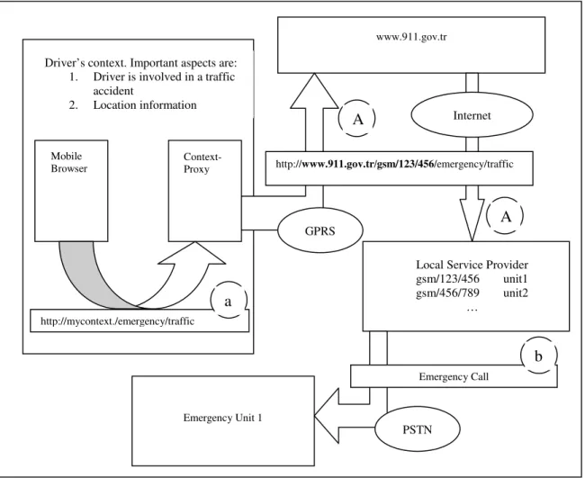
A driver is involved in a car accident at a location unknown to him. He has not lost his consciousness but he is stuck in his car. Since he does not know where he is, he cannot just phone and request for help. But he has got a mobile device on which ContextProxy is running. He just follows a bookmark previously added among his mobile browser’s bookmarks (i.e. http://mycontext./emergency/traffic). The browser makes its request to the virtual host ‘mycontext’ through ContextProxy and ContextProxy modifies this request with the location information that it gathers from the driver’s context and sends the augmented request to the real server ‘www.911.gov.tr’ through a GPRS link. So the request for help has been automatically extended with the location information of the accident. In this scenario two important parts of the driver’s context are reported to the service running on www.911.gov.tr. The first one is the information that the driver is involved in a traffic accident. This information is statically provided through the visited URL (i.e. /emergency/traffic). The other part is the dynamic location information. www.911.gov.tr maintains a central service throughout the country which informs the nearest emergency unit about an accident together with the reported location of the accident. This service does not have to resolve the identity of the nearest emergency unit by itself. It may choose to delegate the resolution of the emergency unit to more local servers. Here is a schematic representation of this scenario:
Figure 2-1. Emergency Requestor
This diagram shows the original request (a) made by the mobile browser and the modified request (A) sent by ContextProxy to the central service provider. The central service provider delegates the task of resolving the nearest emergency unit to a local server. The local server resolves the nearest emergency unit and makes an emergency call (b) to this unit supplying it the location information of the accident. Although not shown on the diagram, the driver is also notified by the central service provider about the estimated time it will take for the emergency unit to arrive.
In this scenario, the difficult part is establishing a country wide location-to-emergency-unit resolution service. However this difficulty is not introduced by the
Driver’s context. Important aspects are: 1. Driver is involved in a traffic
accident
2. Location information
Mobile
Browser Context-Proxy
http://mycontext./emergency/traffic
www.911.gov.tr
http://www.911.gov.tr/gsm/123/456/emergency/traffic
GPRS
Internet
Local Service Provider gsm/123/456 unit1 gsm/456/789 unit2 … . Emergency Unit 1 Emergency Call PSTN a A A b
architecture but rather it is inherently difficult to establish such a service that has to take care of so many diverse contexts.
2.2.2 Location Information Point and Nearest Printer Service
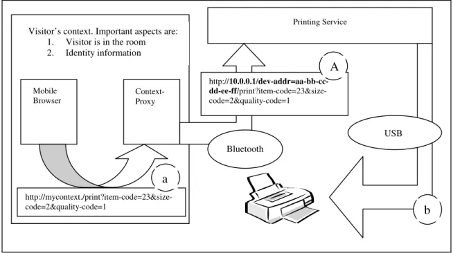
In an art museum, wireless local information points are set up in each room. Each information point serves digital reproductions of the paintings in that room together with some detailed information about each painting formatted as HyperText Markup Language (HTML) documents. A visitor can connect to the local information point of the room he is visiting using his mobile device and browse the information offered by the local service. On the mobile device ContextProxy is running and ContextProxy is configured to access the local information point residing in the room over a Bluetooth link. The visitor’s HTML browser is configured to use ContextProxy as its proxy server. This way when the visitor makes a request for the local content, his browser sends this request to the virtual host ‘mycontext’ through ContextProxy; not even knowing that the request will be fulfilled by a local server accessed through an ad-hoc link. All the connection details are hidden from the legacy HTML browser application and are handled by ContextProxy (assuming that the browser application can be configured to make use of a proxy server which is a very common feature for web clients). The local information point also offers a printing service through which the digital reproductions can be printed. The printing service has HTML user interfaces to allow the visitor to select and to adjust various parameters of the service such as the print quality, size and etc. After selecting the reproduction, the visitor then specifies these settings and submits his request from the browser application. The browser application sends the request to ContextProxy and through the Bluetooth link ContextProxy accesses the printing service. The printing service is preconfigured with the location information of the nearest printer and in response to the request, it guides the user to this nearest printer. In this scenario since short range wireless links are utilized, ContextProxy does not have to augment the requests to provide contextual information. Just accessing the local information server defines the user’s related context. ContextProxy can just act as a
transparent proxy server or it may add some identifying information about the visitor such as the Bluetooth device address of the visitor. Using this identifying information the visitor may then be charged for the printing service when he goes to the nearest printer to get the printed reproduction he purchased. Below we give a schematic representation of this scenario:
Figure 2-2. Local Information Server and Printing Service
As it can be seen on the diagram, ContextProxy replaces the virtual host name in the original request (a) of the mobile browser with the address of the local printing service and appends the Bluetooth device address of the mobile client to the request so that the printing service can identify the client for charging purposes. ContextProxy then sends the modified request (A) to the local printing service. The printing service then translates and forwards the request to the nearest printer (b). Although not shown on the diagram, the visitor is responded with a map showing the location of the nearest printer by the printing service.
Visitor’s context. Important aspects are: 1. Visitor is in the room 2. Identity information
Mobile
Browser Context-Proxy
http://mycontext./print?item-code=23&size-code=2&quality-code=1 Printing Service http://10.0.0.1/dev-addr=aa-bb-cc- dd-ee-ff/print?item-code=23&size-code=2&quality-code=1 Bluetooth USB b a A
2.2.3 Persistent Messages Left to a Place
A student goes to his instructor’s office on the last day for adding/dropping courses to add a new course. But the instructor is not in the room. But luckily he has left the local information server which resides in his room running. The student knows that his instructor is operating a local information server in his room and he checks the availability of this service by initiating a service discovery using his mobile device. The discovery process is carried by ContextProxy which is running on the student’s mobile device. ContextProxy discovers the instructor’s local service and notifies the student with a graphical user interface with an option to connect to the local service. After connecting to the local service over a Bluetooth link, the student follows a hyperlink which resides on the home page of the local information server to see if his instructor has left a message for him. The instructor was also expecting to see the student and so before urgently leaving his office, he has left a message to his student giving information about his whereabouts for the next fifteen minutes. The instructor has also specified a time-to-live value for this message so that the message can only be viewed by the student during fifteen minutes. Also the instructor has targeted the message directly to the student because he does not want other people to learn where he is. The identity information of the student can be provided to the local service using digital certificates or if the security level is acceptable and the Bluetooth device address is accessible, it can be provided by ContextProxy by augmenting the request of the mobile browser with the Bluetooth device address of the student. Here is a schematic representation of this scenario:
Figure 2-3. Persistent Messages Left to a Place
In this figure, the original request made by the mobile browser is labeled with (a) and the modified request is labeled with (A). The messaging service responds to the student with the HTML document labeled with (b). Although the request and response are shown as HTML documents, any other document/messaging format such as XML could be employed as long as it is supported by the mobile client.
Messaging Service Service context. Important aspect is: 1. Time (to manage message lifetimes)
Bluetooth http://10.0.0.1/dev-addr=aa- bb-cc-dd-ee-ff/check-messages
A Student’s context. Important aspects are:
1. Student has come to the office 2. Identity information Mobile Browser Context-Proxy http://mycontext./check-messages a b <html> <head><title> You have a message </title><h1/>
b
2.3 Design and Implementation
2.3.1 Main Design Considerations
ContextProxy was developed in an attempt to provide location-based services and information to nomadic users. The main design goals behind ContextProxy are:
1. Use of existing software/hardware infrastructures and standards to the largest
extent possible: This design goal aims the rapid adaptation of a new
context-aware application infrastructure into the widely available existing
hardware/software infrastructures. There are well established content-delivery protocols (like HTTP) through which huge amounts of content can readily be accessed. Also the Internet contains a vast amount of services with well established interaction schemes. A new application or infrastructure should be easily pluggable into these existing systems if it expects acceptance.
2. Decentralized content and service delivery: One of our goals was to design an architecture in which everyone could set up his own local information server, probably publishing content about himself and about the locality, for nomadic users visiting his place. Such a scenario is best realized with a decentralized architecture because there is actually no need for centralized content and it would be inconvenient to deploy and administer such systems in the presence of a centralized authority. ContextProxy allows for both centralized and decentralized architectures.
3. Easy to use, simple end-user interfaces: Since the nomadic user constantly roams and needs to access a variety of services, he should not be frustrated with
complex configuration tasks to access these services. Also the location
information should be automatically extracted from the user’s context without the user’s attention. If necessary, single-click user interfaces should be provided that will take care of the configuration tasks.
4. Simple and small-footprint mobile device applications: Mobile devices have serious limitations on the computational resources they offer to the application developers. So any architectural component that will reside on these devices should be kept as simple as possible. This will also ensure better portability for these components among various hardware platforms because a specific implementation of an architectural component that will reside on the mobile device will require minimal functionality to be provided by the hardware
platform on which it will run, if it leaves as much functionality as possible to the server side.
2.3.2 Definitions of Architectural Components
2.3.2.1 Service Client
Service client is the architectural component that resides on the user’s mobile device and makes service requests on behalf of the nomadic user. The nomadic user primarily interacts with the user interface provided by the service client. The actual implementation of the service client may change from scenario to scenario. For instance in a scenario where the nomadic user gets information from a local information server, the service client could be the HTML browser running on the mobile phone. Or another example for a typical service client is any mobile application that accesses a web service using Simple Object Access Protocol (SOAP) over HTTP. In the architecture we suggest, service clients can be legacy applications written without the context-awareness concern in mind. The two limitations that our architecture imposes on service clients are:
1. They should communicate with their services using HTTP.
2. They should be configurable to make their requests through a standard HTTP proxy server.
In today’s web oriented world, both of these requirements are met by the vast majority of the web applications. And most of the popular software platforms (i.e. Java, .NET,
Symbian, etc.) readily provide the necessary web based infrastructure on which new service clients meeting these requirements can be developed.
2.3.2.2 ContextProxy
ContextProxy is the architectural component that resides on the user’s mobile device and proxies the requests made by the service client to a remote proxy server (which does not reside on the mobile device). From the service client’s perspective, ContextProxy is a standard HTTP proxy server and from the remote proxy’s perspective, it is a standard HTTP client. In most scenarios this is the primary architectural component which will have to be implemented on the mobile software platform. As stated among our main design goals, our architecture aims to keep the functionality of ContextProxy as simple as possible to promote portability and to reduce software development costs. So ContextProxy is not required to provide a full HTTP proxy server implementation. Instead, it relies on another remote proxy server which has to be a complete HTTP proxy server implementation. The main functionalities that will be provided in a typical implementation of ContextProxy are:
1. Augmenting the service client’s requests with the necessary contextual data which will be interpreted by the context server implementation. The notion of a context server as an architectural component will be explained in a later section. 2. Shielding the service client from the diversity of the connectivity options
encountered in today’s common mobile computing environments (i.e. Bluetooth, Infrared, GPRS, Wifi).
The quality and the types of the services provided by ContextProxy will again differ from scenario to scenario. For instance in an implementation where a GPS receiver is available, ContextProxy could augment the service client’s requests with high accuracy GPS coordinates for outdoor positioning. But in another implementation where a GPS receiver is not available, very low accuracy GSM base station location area codes and cell-ids might be utilized.
2.3.2.3 Remote Proxy
Remote proxy is an architectural component which should normally reside outside of the mobile device. It’s a complete HTTP proxy server implementation and it accepts service requests augmented by ContextProxy. In most web infrastructures remote proxy is readily deployed to secure the clients, to provide anonymity or to increase performance. From the remote proxy’s perspective, ContextProxy is a standard HTTP client making service requests. The remote proxy forwards these service requests to their actual targets (i.e. a context server, or an ordinary content server) and conveys the responses back to ContextProxy.
2.3.2.4 Context Server
Context server is the architectural component that satisfies the service requests of the clients. The implementation of the context server will change from scenario to scenario but a context server can be as simple as a standard web server with a special configuration (section 2.3.5.5 illustrates such a scenario). Service requests augmented with contextual data reach the context server as their final destinations and it is the context server’s responsibility to interpret the contextual data. After extracting the contextual data from the service request and interpreting it, a common implementation will adopt its services according to the context the nomadic user is currently in. In the following sections the term ‘content server’ is used instead of ‘context server’ in situations where the context server does not extract any contextual information from the request but just serves static or dynamic content to the client.
2.3.3 Extracting Location Information from User’s Context
Our implementation of ContextProxy has two ways to extract the location information from the user’s context:
1. From the telephony APIs provided by the operating system it runs on, it can extract the GSM Location Area Code (LAC) and the GSM cell identifier (cell-id) of the GSM base station to which the phone is currently registered. In order to make use of this contextual information a database service of (LAC, cell-id) pair to physical location information mappings should be provided to the context server that will make use of this contextual information. This database of (LAC, cell-id) pair to physical location information mappings can be kept as part of the configuration of the context server as explained in the following sections.
2. It does a Bluetooth device inquiry to determine which other Bluetooth units are within the range of the smart phone ContextProxy is running on. At the end of the inquiry ContextProxy has the device addresses of those units which were in discoverable mode during the inquiry scan initiated by ContextProxy. Again a database of Bluetooth device-address to physical location information mappings is needed to make use of this contextual information. The database may provide more information (i.e. device-address to device-owner mappings) so that more of the user’s context can be revealed. If for example address to device-owner mappings are also provided to the context server, it may adopt its services dynamically according to presence and identities of other people in vicinity of the user of the service.
GSM LAC and GSM cell-id pair only provides a very coarse grained outdoor positioning information since GSM base station coverage is overlapping. But it may be of use in a large settlement like a university campus.
Again just the device addresses of the nearby Bluetooth units do not provide fine grained indoor positioning information. It is generally not enough even to estimate the location of the user at a room level (estimate the room where the user is) because the radio frequency waves used by Bluetooth can penetrate through the walls of a room. But the HCI layer of the Bluetooth stack provides a READ_RSSI command through which it makes the Receiver Signal Strength Indicator (RSSI) related to an active L2CAP link
available. The RSSI values for links established to each of the discovered devices may provide a better estimation of the user’s position. Please refer to chapter 3 for more about this.
2.3.4 Why Symbian?
ContextProxy has been implemented in the Symbian [22] platform. Symbian is a powerful mobile operating system commercially available on various smart phone models from a variety of manufacturers. The choice of Symbian has three main reasons:
1. Since Symbian is an operating system, it allows interaction with low level hardware which is necessary to gather information about the user’s context. It has various communication and networking APIs and it supports sockets. It has telephony APIs to gather information about the currently registered GSM base station and it has Bluetooth APIs. Although not utilized in ContextProxy, Symbian also provides APIs for infrared communications.
2. Since Symbian runs on smart phones, the developer has many means for communication. For the development of ContextProxy, a Nokia 6600 smart phone was used. This smart phone has various connectivity options [23] including Bluetooth, infrared, General Packet Radio Service (GPRS) and High Speed Circuit Switched Data (HSCSD).
3. Besides the variety of the connectivity options, most smart phones offer on-device peripherals that can be utilized to collect contextual information. For instance the Nokia 6600 has an on-board VGA camera. Symbian APIs allow interaction with these peripherals but currently ContextProxy does not make use of them.
For the implementation of ContextProxy, other mobile platforms such as Pocket PC 2003 can of course be used. The only limitation imposed on the platform is that it should support server side sockets. Also the platform needs to support the contextual sensing technologies (such as GPS) which are to be used to collect data from the user’s context.
![Figure 1-9. The ORL mobile transmitter [16]](https://thumb-eu.123doks.com/thumbv2/9libnet/5649054.112527/30.918.350.634.563.776/figure-the-orl-mobile-transmitter.webp)