Digital decoding of in -line holograms
Levent OnuralBilkent University
Electrical and Electronics Engineering Department P.K. 8, 06572 Maltepe
Ankara, Turkey
Peter D.Scott
State University of New York at Buffalo
Electrical and Computer Engineering Department Laboratory for Power and Environmental Studies Amherst, New York 14260
CONTENTS
1. Introduction
2. Problem formulation for 2 -D system representation 3. The reconstruction algorithm
4. Physical interpretation of the truncated inverse filter 5. Digital implementation of the truncated inverse filter 6. Results
7. Conclusions
8. Appendix: some related formulas 9. References
Abstract.Digitally sampled in -line hologramsmay be linearly filtered to recon-struct a representation of the original object distribution, thereby decoding the information contained in the hologram. The decoding process is performed by digital computation rather than optically. Substitution of digital for optical decoding has several advantages, including selective suppression of the twin -image artifact, elimination of the far -field requirement, and automation of the data reduction and analysis process. The proposed filter is a truncated series expansion of the inverse of that operator that maps object opacity function to hologram intensity. The first term of the expansion is shown to be equivalent to conventional (optical) reconstruction, with successive terms increasingly sup-pressing the twin image. The algorithm is computationally efficient, requiring only a single fast Fourier transform pair.
Subject terms: in -line holography; digital holography; image processing; inverse filtering. Optical Engineering 26(11), 1124 -1132 (November 1987).
1. INTRODUCTION
An in -line hologram (see Fig. 1) captures, with high resolu-tion, the three -dimensional location and cross -sectional mor-phology of every object within a thick volume (corresponding
to several thousand depths of field of conventional photog-raphy1). Since object and reference waves are the diffracted
and undiffracted components of a single beam, with no
addi-tional optics required, the recording system is remarkably
simple and well suited for adverse industrial and field
environments.In spite of these attractive features, in -line holography found few practical applications from its discovery until the
mid- 1960s, when Thompson demonstrated the effectiveness of the technique in visualizing particle fields and aerosols.2-4
The principal drawback that limited application of in -line
Paper 2321 received Aug. 4,1986; revised manuscript received June 10,1987; accepted for publication June 15,1987; received by Managing Editor June 17,
1987.
n 1987 Society of Photo -Optical Instrumentation Engineers.
1124 / OPTICAL ENGINEERING / November 1987 / Vol. 26 No. 11
holography is an undesirable defocused twin image overlaid on the desired focused image in the standard reconstruction.
Especially in holograms recorded in the Fresnel zone, image and twin image intermingle in complex patterns, causing
dif-ficulty in defining the correct object boundaries. Thompson pointed out that in reconstructions from holograms recorded in the Fraunhofer zone, however, these two image compo-nents are quite distinguishable and thus easily discerned. Restricting attention to ensembles of small compact objects
such as particles and droplets, it is possible to locate the
holographic medium in both the Fraunhofer zone of the
individual objects and the Fresnel zone of the ensemble. Thisalleviates the twin -image problem, yet the cross -section
planar locations of the particles can be easily detected directly
from the hologram. Although the twin image is present with
undiminished amplitude, its relative lack of interference with object boundary visualization has permitted particle field and aerosol analysis to develop as the most prominent application of in -line holography. Useful reviews of progress in particle field holography include Refs. 1, 5, and 6.
Efforts to alleviate the twin -image problem in a more general setting, while dating nearly from the inception of
holography itself, have met with limited success. Early optical
methods are reviewed by Collier et al.' Here we present an
alternative remedy to the twin -image problem, one that does
not require that in -line holograms be recorded in the
Fraun-hofer zone of individual particles. The overall reconstruction
process is treated as a signal processing problem, and the
solution is implemented digitally. Rather than enforce restric-tions that make the twin image look different from the desired
Digital decoding of in-line holograms
Levent Onural
Bilkent University
Electrical and Electronics Engineering Department P.K. 8, 06572 Maltepe
Ankara, Turkey
Peter D. Scott
State University of New York at Buffalo
Electrical and Computer Engineering Department Laboratory for Power and Environmental Studies Amherst, New York 14260
Abstract. Digitally sampled in-line holograms may be linearly filtered to recon-
struct a representation of the original object distribution, thereby decoding the information contained in the hologram. The decoding process is performed by digital computation rather than optically. Substitution of digital for optical decoding has several advantages, including selective suppression of the twin- image artifact, elimination of the far-field requirement, and automation of the data reduction and analysis process. The proposed filter is a truncated series expansion of the inverse of that operator that maps object opacity function to hologram intensity. The first term of the expansion is shown to be equivalent to conventional (optical) reconstruction, with successive terms increasingly sup- pressing the twin image. The algorithm is computationally efficient, requiring only a single fast Fourier transform pair.
Subject terms: in-line holography; digital holography; image processing; inverse filtering. Optical Engineering 26(11), 1124-1132 (November 1987).
CONTENTS 1. Introduction
2. Problem formulation for 2-D system representation 3. The reconstruction algorithm
4. Physical interpretation of the truncated inverse filter 5. Digital implementation of the truncated inverse filter 6. Results
7. Conclusions
8. Appendix: some related formulas 9. References
1. INTRODUCTION
An in-line hologram (see Fig. 1) captures, with high resolu- tion, the three-dimensional location and cross-sectional mor- phology of every object within a thick volume (corresponding to several thousand depths of field of conventional photog- raphy 1 ). Since object and reference waves are the diffracted and undiffracted components of a single beam, with no addi- tional optics required, the recording system is remarkably simple and well suited for adverse industrial and field environments.
In spite of these attractive features, in-line holography found few practical applications from its discovery until the mid-1960s, when Thompson demonstrated the effectiveness of the technique in visualizing particle fields and aerosols. 2 "4 The principal drawback that limited application of in-line Paper 2321 received Aug. 4, 1986; revised manuscript received June 10,1987; accepted for publication June 15,1987; received by Managing Editor June 17,
1987.
© 1987 Society of Photo-Optical Instrumentation Engineers.
holography is an undesirable defocused twin image overlaid on the desired focused image in the standard reconstruction. Especially in holograms recorded in the Fresnel zone, image and twin image intermingle in complex patterns, causing dif- ficulty in defining the correct object boundaries. Thompson pointed out that in reconstructions from holograms recorded in the Fraunhofer zone, however, these two image compo- nents are quite distinguishable and thus easily discerned. Restricting attention to ensembles of small compact objects such as particles and droplets, it is possible to locate the holographic medium in both the Fraunhofer zone of the individual objects and the Fresnel zone of the ensemble. This alleviates the twin-image problem, yet the cross-section planar locations of the particles can be easily detected directly from the hologram. Although the twin image is present with undiminished amplitude, its relative lack of interference with object boundary visualization has permitted particle field and aerosol analysis to develop as the most prominent application of in-line holography. Useful reviews of progress in particle field holography include Refs. 1, 5, and 6.
Efforts to alleviate the twin-image problem in a more general setting, while dating nearly from the inception of holography itself, have met with limited success. Early optical methods are reviewed by Collier et al. 7 Here we present an alternative remedy to the twin-image problem, one that does not require that in-line holograms be recorded in the Fraun- hofer zone of individual particles. The overall reconstruction process is treated as a signal processing problem, and the solution is implemented digitally. Rather than enforce restric- tions that make the twin image look different from the desired 1124 / OPTICAL ENGINEERING / November 1987 / Vol. 26 No. 11
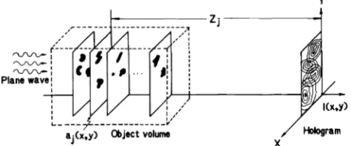
a.(x.y) abject volume
X Fig. 1. In -line hologram recording: multiplanar model.
focused image component, we digitally filter the sampled
hologram to selectively suppress the undesired component of the resulting reconstruction while preserving the desired
com-ponent. This eliminates confusion between object and twin
image even in circumstances that challenge the far -field dis-tinguishability assumption, such as dense ensembles of
irregu-lar particles where random phase relations between adjacent
twin images create patterns difficult to distinguish from actual particles. Removal of the Fraunhofer (far -field) requirement
further permits broad dispersions of particle sizes within a single hologram, thus extending the range of application of the in -line technique to scenes in which it is not possible to
record in the far field of the larger particles while adequately
resolving each smaller one. In addition, the digital decoding process presented in this paper represents progress toward automation of the data reduction and analysis process.
Parti-cle field and aerosol holograms tend to be data -intensive, and
the need for objective, automated data reduction has often
been cited (see, for example, Refs. 8 and 9).
Decoding of in -line holograms by digital signal processing technique is a new and promising direction. An early approach used direct clipping for artifact suppression.'° A more recent study employs a phase retrieval algorithm to iteratively
recon-struct the phase component, which is lost during the optical
recording of the hologram." Once the phase is obtained with the help of constraints, the reconstruction is free of the
unde-sired twin image. However, a drawback of such iterative
algorithms, including the phase retrieval, is the considerable number of iterations and computation time required.
The technique presented in this paper uses a truncated inverse filtering approach that is computationally efficient and is effective in suppressing the twin image in the recon-structions. Once the desired image has been reconstructed,
further image processing may be done for finding the
periph-eral contours of the objects captured in the hologram. 2. PROBLEM FORMULATION FOR 2 -D SYSTEM
REPRESENTATION
The signals and transforms of in -line holography may be
derived and expressed from a variety of perspectives empha-sizing, variously, physical optics,12 -14 system theoretic,13 or
particle field application's aspects. Here we adopt a
nota-tional scheme based on the observation that planar holograms and their planar reconstructions are ensembles of two-
dimen-sional signals and thus are amenable to sampling, filtering,
and other standard two -dimensional signal processing
operations.An in -line hologram is captured as in Fig. 1. A plane wave
of coherent radiation (wavelength X) propagating in the
a(x.y)
Plane wave
Y
Object plane
X
Fig. 2. In -line hologram recording: single object plane. IZ(x.y)
z- direction illuminates a sample volume containing multiple
small objects that diffract this incident field. Without loss of
generality, we assume the phase of the plane wave at the
hologram plane to be zero. Each object is taken to be vanish-ingly thin in the z- direction, i.e., a pure cross -sectional object, so that the ensemble of these objects may be described by a set of two -dimensional opacity functions ai (x, y),j = 1, 2,... ,N. Here, aj (x, y) = 1if an opaque particle in the plane at a
distance zi from the hologram plane covers the point (x,y);
a (x , y) = 0 if the zj plane is transparent at (x , y); for general
objects ai (x, y)is a complex function. However, to guarantee
convergence of the algorithm to be introduced in the next section, we restrict the object distribution to be strictly real (for instance, opaque particles). Uncertain convergence for objects of variable phase is a significant limitation to the algorithm in its present form.
If all objects occupied the single plane at a distance z from the hologram plane (see Fig. 2) with opacity function a(x, y), then the scalar field produced at the hologram plane could be expressed as the Fresnel- Kirchhoff integral,
= Bexp(
-jkz)f J'[l
-a(e,n))
-oc _ocexp(jkz) (
r
X
jz
expS jz [(x -
022 +-
n)Zl)\ldedn, (I) where k =27r/ X, B is the amplitude of the incident plane wave(hereafer taken as unity), and -kz is the phase of the illumi-nating wave at the object plane. Denoting the convolution
kernel of this integral as
ex kz
h(x,Y) P ) eXp j ir
z (x2 +
y2]
, (2)
we can express the field Eq. (1) more compactly as the 2 -D
convolution
ik(x,Y) = exp( jkz) [l - a(x,Y)]**h? (x,Y) (3)
of the inpulse response 17i7(x,y) with the 2 -D input signal
exp(- jkz)[l - a(x,y)]. It is convenient to define another
impulse response h7(x, y), related to h7(x, y) by a phase shift: Plane wave_—.£—————
aj(x,y) Object volume Hologram
Fig. 1. In-line hologram recording: multiplanar model.
focused image component, we digitally filter the sampled hologram to selectively suppress the undesired component of the resulting reconstruction while preserving the desired com- ponent. This eliminates confusion between object and twin image even in circumstances that challenge the far-field dis- tinguishability assumption, such as dense ensembles of irregu- lar particles where random phase relations between adjacent twin images create patterns difficult to distinguish from actual particles. Removal of the Fraunhofer (far-field) requirement further permits broad dispersions of particle sizes within a single hologram, thus extending the range of application of the in-line technique to scenes in which it is not possible to record in the far field of the larger particles while adequately resolving each smaller one. In addition, the digital decoding process presented in this paper represents progress toward automation of the data reduction and analysis process. Parti- cle field and aerosol holograms tend to be data-intensive, and the need for objective, automated data reduction has often been cited (see, for example, Refs. 8 and 9).
Decoding of in-line holograms by digital signal processing technique is a new and promising direction. An early approach used direct clipping for artifact suppression. 10 A more recent study employs a phase retrieval algorithm to iteratively recon- struct the phase component, which is lost during the optical recording of the hologram. 11 Once the phase is obtained with the help of constraints, the reconstruction is free of the unde- sired twin image. However, a drawback of such iterative algorithms, including the phase retrieval, is the considerable number of iterations and computation time required.
The technique presented in this paper uses a truncated inverse filtering approach that is computationally efficient and is effective in suppressing the twin image in the recon- structions. Once the desired image has been reconstructed, further image processing may be done for finding the periph- eral contours of the objects captured in the hologram.
2. PROBLEM FORMULATION FOR 2-D SYSTEM REPRESENTATION
The signals and transforms of in-line holography may be derived and expressed from a variety of perspectives empha- sizing, variously, physical optics, 12 " 14 system theoretic, 13 or particle field application 15 aspects. Here we adopt a nota- tional scheme based on the observation that planar holograms and their planar reconstructions are ensembles of two-dimen- sional signals and thus are amenable to sampling, filtering, and other standard two-dimensional signal processing operations.
An in-line hologram is captured as in Fig. 1. A plane wave of coherent radiation (wavelength A) propagating in the
Object plane
Fig. 2. In-line hologram recording: single object plane.
z-direction illuminates a sample volume containing multiple small objects that diffract this incident field. Without loss of generality, we assume the phase of the plane wave at the hologram plane to be zero. Each object is taken to be vanish- ingly thin in the z-direction, i.e., a pure cross-sectional object, so that the ensemble of these objects may be described by a set of two-dimensional opacity functions a- (x, y), j — 1, 2,..., N. Here, aj(x,y) = 1 if an opaque particle in the plane at a distance Zj from the hologram plane covers the point (x,y); aj(x,y) = 0 if the z- plane is transparent at (x,y); for general objects aj(x,y) is a complex function. However, to guarantee convergence of the algorithm to be introduced in the next section, we restrict the object distribution to be strictly real (for instance, opaque particles). Uncertain convergence for objects of variable phase is a significant limitation to the algorithm in its present form.
If all objects occupied the single plane at a distance z from the hologram plane (see Fig. 2) with opacity function a(x, y), then the scalar field produced at the hologram plane could be expressed as the Fresnel-Kirchhoff integral,
00 00 Az (x,y) = Bexp(-jkz)J J[, -.(*,, — OO —00 /exp(jkz) X rr exp 1 *'~ I A* f/ (1)
where k = 2yr/ A, B is the amplitude of the incident plane wave (hereafer taken as unity), and kz is the phase of the illumi- nating wave at the object plane. Denoting the convolution kernel of this integral as
- . exp(jkz) f TT . ,1
hz (x,y) A ^L_L exp h (x2 + y2 ) , (2)
we can express the field Eq. (1) more compactly as the 2-D convolution
= exp(-jkz)[l - a(x,y)]**hz (x,y) (3)
of the inpulse response hz (x,y) with the 2-D input signal exp( jkz)[l a(x,y)]. It is convenient to define another impulse response hz (x, y), related to hz (x, y) by a phase shift:
ONURAL, SCOTT
1 7r
hz(x,y) exp(- Jkz)hz(x,y) = e(p[j
Jz (x2 +)12)] (4) With this definition, Eq. (3) becomes
+IIz(x,y) _ [1 - a(x,y)] **hz(x,y) (5)
Denoting the modulus squared (intensity) of the resultant
field as IZ(x, y) and using the identity 1 **hZ(x,y) = 1 (see the appendix),
1z(x,y) = Úrz(x,y)I/4i(x,y) (6)
becomes
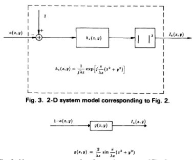
lz(x,y) = 1 - a(x,y) * *hz(x,y)I2 (7) Since the film used to record the hologram is sensitive to the intensity of the field on the hologram plane, 17(x,y) will also be referred to as the hologram of a (x , y) taken at a distance z. The system model corresponding to Fig. 2 is shown in Fig. 3. Expanding Eq. (7), we obtain
lz(x,y) = 1 -a *(x,y)**h*z(x,y) - a(x,y)**hz(x,y)
+ Ia(x,y) * *hz(x,y)I2 (8)
When the hologram is reilluminated, the first term will lead to
a uniform component, the second and third terms to the real
and virtual images of the object distribution, respectively, and
the final term to a nonlinear component. For high quality
optical reconstructions, this final term must be dominated by
the other image components. This is conventionally
guaran-teed by requiring that the rms power in the undiffracted
(directly transmitted) reference wave over the hologram be much greater than that of the diffracted object wave; i.e.,
0 < II a(x , y) IIrms« 1. Under this assumption, the final term in Eq. (8) is dominated in the rms sense over the hologram by each of the other terms and may be neglected.
To guarantee convergence of the result of the twin -image
elimination algorithm to the desired object distribution, we
hereafter assume each ai (x, y) to be a real -valued function. As
a consequence of this assumption, the algorithm of Sec. 3 cannot be used for general objects with complex- valued
transmittance functions.
Dropping the dominated last term of Eq. (8) and merging
the preceding pair of terms with a(x, y) (assumed real valued), we obtain
IZ(x,y) = 1 - a(x,y)**2Re{hZ(x,y)} . (9)
Under these assumptions, the in -line hologram IZ(x, y) is seen to be the shifted output of a two -dimensional linear filter with
input -a(x
, y) andimpulse response g(x, y) 2Re {hz(x, y) }, asshown in Fig. 4.
If the object distribution occupies several planes instead of a single plane, multiple diffraction effects must be considered. For instance, the radiation incident on the second object plane
is the superposition of the propagated plane wave originally incident on the first object plane and the object wave
dif-fracted by the first plane. However, under the assumption that the diffracted wave has much less energy than the transmitted
plane wave, the field incident on the second object plane is
1126 / OPTICAL ENGINEERING / November 1987 / Vol. 26 No. 11
I-h,.(x,U)
e%pliA (='+y')]
L
J
Fig. 3. 2 -D system model corresponding to Fig. 2.
1-a(x,Y)
9(x,y)=
Azein -(x'+A. V')
Fig.4. Linear system approximation to the system of Fig. 3; a (x, y) is real valued.
dominated by its plane wave component and may be com-puted as above. The field on the hologram plane is then
Vr(x,y) = I -1 ai(x,y)**hr )(x,y) , (10)
where the sum is taken over all object planes, and taking the modulus squared (with dominated nonlinear components dropped), the resulting hologram is
1(x,y) = 1 -1 ai(x,y)**2Re{hZ.(x,y)} . (l l)
,
Comparing Eqs. (11) and (9), the hologram in the general multiplanar case is just a shifted superposition of holograms of planar object distributions.
For simplicity, we will derive the reconstruction and twin
-image suppression formulas for the single plane case. It is straightforward to expand these formulas for multiplanar
object distributions.
Conventionally, reconstruction is performed by reillumi-nating the developed hologram plate with the same coherent illumination and imaging at the same distance as the
holo-gram was originally recorded. Therefore, the above
formula-tion for recording is also valid for reconstrucformula-tion. Since the hologram plate replaces the object plane, the transmittance function I -a (x, y) in the aboveformulas must be replaced by the amplitude transmittance of the hologram plate. Assuming
that the recording medium has a linear characteristic, the
amplitude transmittance of the hologram will be e + biz (x , y),
where e and b are constants. The constant b is negative for
negative recording. Assuming a positive recording, the
trans-mittance function can be rewritten as d + lz(x,y), with
con-stants gathered in d. Therefore, the field at the imaging plane due to the illumination of the positive hologram is given by
OZ(x,y) = [d + lz(x,y)] **hz(x,y) , (12)
which is obtained by replacing 1 - a(x, y) of Eq. (5) by d +
ONURAL, SCOTT
hz (x,y) A exp(-jkz)hz (x,y) = ^- exp fj -^ (x2 + y2)! . (4)
With this definition, Eq. (3) becomes
<Az (x,y) = [1 -a(x,y)]**hz (x,y) . (5)
Denoting the modulus squared (intensity) of the resultant field as Iz (x,y) and using the identity 1 **hz (x,y) = 1 (see the appendix),
Iz (x,y) = </rz (x,y)<A*(x,y)
becomes
Iz (x,y) = |l-a(x,y)**hz (x,y)| 2
(6)
(7)
Since the film used to record the hologram is sensitive to the intensity of the field on the hologram plane, Iz (x, y) will also be referred to as the hologram of a (x, y) taken at a distance z. The system model corresponding to Fig. 2 is shown in Fig. 3. Expanding Eq. (7), we obtain
Iz (x,y) = 1 -a*(x,y)**h*(x,y) - a(x,y)**hz (x,y)
+ |a(x,y)**hz (x,y)| 2 . (8)
When the hologram is reilluminated, the first term will lead to a uniform component, the second and third terms to the real and virtual images of the object distribution, respectively, and the final term to a nonlinear component. For high quality optical reconstructions, this final term must be dominated by the other image components. This is conventionally guaran- teed by requiring that the rms power in the undiffracted (directly transmitted) reference wave over the hologram be much greater than that of the diffracted object wave; i.e., 0<||a(x,y)|| rms « 1. Under this assumption, the final term in Eq. (8) is dominated in the rms sense over the hologram by each of the other terms and may be neglected.
To guarantee convergence of the result of the twin-image elimination algorithm to the desired object distribution, we hereafter assume each a} (x, y) to be a real-valued function. As a consequence of this assumption, the algorithm of Sec. 3 cannot be used for general objects with complex-valued transmittance functions.
Dropping the dominated last term of Eq. (8) and merging the preceding pair of terms with a(x, y) (assumed real valued), we obtain
Iz (x,y) = 1 -a(x,y)**2Re{hz (x,y)} (9)
Under these assumptions, the in-line hologram Iz (x, y) is seen to be the shifted output of a two-dimensional linear filter with input a(x, y) and impulse response g(x, y) A 2 Re {hz (x, y)}, as shown in Fig. 4.
If the object distribution occupies several planes instead of a single plane, multiple diffraction effects must be considered. For instance, the radiation incident on the second object plane is the superposition of the propagated plane wave originally incident on the first object plane and the object wave dif- fracted by the first plane. However, under the assumption that the diffracted wave has much less energy than the transmitted plane wave, the field incident on the second object plane is
Fig. 3. 2-D system model corresponding to Fig. 2.
l-a(x.y) /.(*,»)
Fig. 4. Linear system approximation to the system of Fig. 3; a(x,y) is real valued.
dominated by its plane wave component and may be com- puted as above. The field on the hologram plane is then
(10)
where the sum is taken over all object planes, and taking the modulus squared (with dominated nonlinear components dropped), the resulting hologram is
-Saj (x,y)**2Re{hZj (x,y)J (11)
Comparing Eqs. (11) and (9), the hologram in the general multiplanar case is just a shifted superposition of holograms of planar object distributions.
For simplicity, we will derive the reconstruction and twin- image suppression formulas for the single plane case. It is straightforward to expand these formulas for multiplanar object distributions.
Conventionally, reconstruction is performed by reillumi- nating the developed hologram plate with the same coherent illumination and imaging at the same distance as the holo- gram was originally recorded. Therefore, the above formula- tion for recording is also valid for reconstruction. Since the hologram plate replaces the object plane, the transmittance function 1 a(x,y) in the above formulas must be replaced by the amplitude transmittance of the hologram plate. Assuming that the recording medium has a linear characteristic, the amplitude transmittance of the hologram will be e + blz (x, y), where e and b are constants. The constant b is negative for negative recording. Assuming a positive recording, the trans- mittance function can be rewritten as d + Iz (x,y), with con- stants gathered in d. Therefore, the field at the imaging plane due to the illumination of the positive hologram is given by
0z (x,y) = [d + Iz (x,y)]**hz (x,y) , (12) which is obtained by replacing 1 a(x,y) of Eq. (5) by d +
Iz(x,y). Equation (12) can be rewritten as
(1),(x ,y) = d + 17(x,y) * *hz(x,y) . (13)
Substituting Eq. (8) into this expression and expanding the
components, we obtain
c/),(x,Y) = d + 1 -a *(x,Y) * *hi(x,Y) * *h,(x,Y)
- a(x,Y) * *hz(x,Y) * *hz(x,Y) (14)
These components can be simplified using properties of
h7(x,y) shown in the appendix:h,k(x,Y) * *Iyx,Y) = hz._zk(x,Y) , (15)
h,k(x,Y) * *hzj(x,Y) = h1j+Zk(x,Y) , (16)
ha(x,Y) = S(x,Y) , (17)
to yield
(1),(x ,y) = d + 1 -a *(x,y) * *S(x,y) - a(x,y) * *h2z(x,y)
= d -a *(x,y) + [I - a(x,y) * *h27(x,y)] . (18)
Note that the second term is the desired reconstruction. The term in the brackets is exactly the field of a hologram of the object that would be present at a distance 2z, or twice the
distance of the original recording. This term is the twin image. Thus, from Eqs. (5) and (18),
0),(x ,y) = d -a *(x,Y) + rzz(x,Y) (19)
It is impossible to observe or record the field in optical
reconstructions. Only its intensity can be recorded. Therefore,the object reconstruction is taken to be proportional to the intensity of this field. This will yield additional undesired
nonlinear components. In digital reconstruction, it is possible to compute and record the field directly. Note that the average
level of the hologram I(x,y) can be modified to improve the
quality. For example, adding a large bias suppresses the
nonlinear terms in the intensity of the reconstruction field
RZ(x,y), since
Rz(x,Y) = 07(x,Y)4)*z(x,Y)
= d2 - 2Re {da *(x,y)} -2 Re {d 027(x , y)}
+ Ia(x,Y)12 + +2 (x,Y)12
If d is large, then the last two terms are dominated.
The purpose of this paper is to present a new method for
object reconstruction from in -line holograms that suppresses the twin image 1r2z(x, y). An algorithm is obtained by treating
the reconstruction as an inverse problem. This algorithm is implemented digitally by computer. In this paper the basic
structure of the algorithm, its digital implementation, and the results in particle field applications are presented.
the given assumptions (see Figs. 3 and 4). The system shown in
Fig. 3 or in Fig. 4 can be converted to a discrete system and easily implemented digitally. In this case, if the input is a
sampled object distribution a (x , y), then the output will be the simulated sampled in -line hologram of that object. If the input
is a digitized hologram, then the output will simulate the
conventional reconstruction.
Taking as the goal the reconstruction of a(x,y) from
I1(x , y), the system model of Fig. 4 suggests the use of a system that inverts the forward transformation. Here we present a
linear filter designed to decode the object a(x, y)directly from
its in -line hologram IZ (x, y). Theprincipal achievement of this
approach is the suppression of the twin image. Furthermore,
since the filtering operation is performed completely by digital
means, the optical reconstruction step is eliminated.
Since the hologram IZ(x,y) for real- valued a(x, y) is given as
the output of a linear system [see both Fig. 4 and Eq. (9)], a
linear inverse filter is sought. The 2 -D Fourier transform of the impulse response g(x,y) (the frequency response) is given by
G(u,v) = ,F{2Re{h(x,y)}}
_
2 zr -Xz sinÁz
(x2 + y2) Xz = 2cos -47 (u2 + v2) , (21)where u and v are the transform domain variables. G (u, v) has
uncountably many zeros, so 1/ G (u , v) does not exist. An inverse c (u, v) satisfying
1 - W(u,v)G(u,v) = 0 V(u,v) E R2 (22) cannot be found. However, we can find an L2 inverse (u , v)
satisfying
ff
-
(u,v)G(u,v)12dudv = 0 (23)It is proved in Ref. 16 that the filter given by
M(u,v) = cos
4ír (u2 + v2)2m -1 M M - 1 - Q to gz k
(20)
+ Lr
M
Sk(u,v) ,3. THE RECONSTRUCTION ALGORITHM
We showed in the previous section that in -line hologram recording, as well as conventional reconstruction, can be modeled as a simple linear shift invariant 2 -D system under
k=i
(24)
Sk(u,v) _ (- 1)kcos 4 (2k + 1) (u2 + v2) ,
is a series approximation to the desired inverse and converges to it in the energy or L2 metric (23) as M - 00. Application of
this linear filter with any finite M to the hologram yields a
constant term and a residual error term in addition to the
desired reconstructed object. It is not desirable to approxi-mate the exact inverse too closely, since for large M such a function inherits the same undesirable properties as the true inverse, most notably high gain near the zeros of G(u,v). In
our experience M selected in the range 3 to 5 works
satisfac-torily for particle field holograms. For M = 1
(first -orderIz (x,y). Equation (12) can be rewritten as
</>z (x,y) - d + Iz (x,y)**hz (x,y) . (13)
Substituting Eq. (8) into this expression and expanding the components, we obtain
c/>z (x,y) = d + 1 -a*(x,y)**h*(x,y)**hz (x,y)
- a(x,y)**hz (x,y)**hz (x,y) . (14)
These components can be simplified using properties of hz (x,y) shown in the appendix:
h*Zk (x,y)**hZj (x,y) - hZj _ Zk (x,y) , (15) hZk (x,y)**hZj (x,y) - hZj + Zk (x,y) , (16)
h0 (x,y) - <5(x,y) , (17)
to yield
c/>z (x,y) = d + 1 - a*(x,y)**6(x,y) - a(x,y)**h2z (x,y) - d - a*(x,y) -f [1 - a(x,y)**h2z (x,y)] . (18)
Note that the second term is the desired reconstruction. The term in the brackets is exactly the field of a hologram of the object that would be present at a distance 2z, or twice the distance of the original recording. This term is the twin image. Thus, from Eqs. (5) and (18),
,y) = d-a*(x,y) + <A2z (x,y) . (19)
It is impossible to observe or record the field in optical reconstructions. Only its intensity can be recorded. Therefore, the object reconstruction is taken to be proportional to the intensity of this field. This will yield additional undesired nonlinear components. In digital reconstruction, it is possible to compute and record the field directly. Note that the average level of the hologram I(x,y) can be modified to improve the quality. For example, adding a large bias suppresses the nonlinear terms in the intensity of the reconstruction field Rz (x,y), since
Rz (x,y) - </>z (x,y)4>*z (x,y)
- d2 - 2Re{da*(x,y)} - 2Re{diA2z (x,y)}
+ |a(x,y)| 2 + |iA2z (x,y)| 2 . (20)
If d is large, then the last two terms are dominated.
The purpose of this paper is to present a new method for object reconstruction from in-line holograms that suppresses the twin image i//2z (x, y). An algorithm is obtained by treating the reconstruction as an inverse problem. This algorithm is implemented digitally by computer. In this paper the basic structure of the algorithm, its digital implementation, and the results in particle field applications are presented.
3. THE RECONSTRUCTION ALGORITHM
We showed in the previous section that in-line hologram recording, as well as conventional reconstruction, can be modeled as a simple linear shift invariant 2-D system under
the given assumptions (see Figs. 3 and 4). The system shown in Fig. 3 or in Fig. 4 can be converted to a discrete system and easily implemented digitally. In this case, if the input is a sampled object distribution a (x, y), then the output will be the simulated sampled in-line hologram of that object. If the input is a digitized hologram, then the output will simulate the conventional reconstruction.
Taking as the goal the reconstruction of a(x,y) from Iz (x, y), the system model of Fig. 4 suggests the use of a system that inverts the forward transformation. Here we present a linear filter designed to decode the object a(x, y) directly from its in-line hologram Iz (x, y). The principal achievement of this approach is the suppression of the twin image. Furthermore, since the filtering operation is performed completely by digital means, the optical reconstruction step is eliminated.
Since the hologram Iz (x, y) for real-valued a(x, y) is given as the output of a linear system [see both Fig. 4 and Eq. (9)], a linear inverse filter is sought. The 2-D Fourier transform of the impulse response g(x,y) (the frequency response) is given by
G(u,v) = Jr {2Re{hz (x,y)}}
Xz _ .
= 2cos -(u2 + v2) ,
4?r (21)
where u and v are the transform domain variables. G(u, v) has uncountably many zeros, so l/G(u,v) does not exist. An inverse <& (u, v) satisfying
- <S(u,v)G(u,v) = 0 V(u,v) E R2 (22)
cannot be found. However, we can find an 1^ inverse ® (u, v) satisfying
j I |1 -®(u,v)G(u,v)| 2 dudv = 0 .
—OO —00
It is proved in Ref. 16 that the filter given by
(23) ® M (u,v) - cos-' 47T ' 2 M-1_,
+ 2
k = i * T / M - 1 - |[log2 k]l M (24) Sk ( u ,v) = (-l)k cos-^-(2k + l)(u2 + v2) ,is a series approximation to the desired inverse and converges to it in the energy or L2 metric (23) as M -> <*>. Application of this linear filter with any finite M to the hologram yields a constant term and a residual error term in addition to the desired reconstructed object. It is not desirable to approxi- mate the exact inverse too closely, since for large M such a function inherits the same undesirable properties as the true inverse, most notably high gain near the zeros of G(u, v). In our experience M selected in the range 3 to 5 works satisfac- torily for particle field holograms. For M = 1 (first-order
ONURAL, SCOTT
approximation) the approximate inverse filter, Eq. (24), is
equivalent to the conventional reconstruction since
2u1(u,v) = G(u,v) . (25)
Additional terms tend to enhance suppression of the twin
image and thus improve the quality of the reconstruction. As
more terms are added, however, the residual twin image
rapidly declines in rms value, and further improvement must be traded off against small but inevitable degradations due to finite word length and modeling errors.4. PHYSICAL INTERPRETATION OF THE TRUNCATED INVERSE FILTER
The truncated inverse filter as defined by Eq. (24) may be given a physical interpretation. In fact, the main result sum-marized in Eq. (24) was discovered as a consequence of
for-malizing the arguments presented in this section.
For real -valued a(x, y), the real and imaginary parts of the field given by Eq. (18) are
Re{C(x,y)} = d + l - a(x,y) - a(x,y)** Re{h2z(x,y)}
Od+1+bz(x,y),
Im{cb,(x,y)} = -a(x,y)**Im{h2z(x,y)}
gz(x,Y)
(26)
(27)
The desired component a(x,y) is present in the real part
bz(x,y). In addition, bz(x,y) has the real part of the twin
image superposed to a(x, y). On the other hand, qz(x, y)con-sists of only the imaginary part of the twin image. A useful
observation is that qz (x,y) is itself very similar to a hologram, with the distance parameter 2z; Im {h2z(x,y)) is the
convolu-tion kernel, instead of Re {hz(x, y)} [see Eq. (9)]. So we can use
qz (x , y) as if it were a new hologram containing added (quad
-rature) information to be reconstructed. In fact, using the
properties cited in the appendix,
I I
Im{hkz(x,y)}**Im{hkz(x,y)} = 2 S(x,y) -2 Re{h2kz(x,y)}, (28)
1
Im{hkz(x,y)}**Re{hkz(x,y)} = 21m{h2kz(x,y)} , (29)
the propagating components of this "quadrature hologram"
can be computed at 2z as qz(x , y) ** 2Im {h2z(x, y)} = -2a(x,y)**Im{h2z(x,y)}**Im{h2z(x,y)} = -a(x,y)**S(x,y) + a(x,y)**Re{h4z(x,y)} = -a(x,y) + a(x,y)**Re{h4z(x,y)} p27(x,Y) , gz (x , y) * * 2 Re {h2z ( x , y) } = -2a(x,y)**Im{h2Z(x,y)1**Re{h2z(x,y)J = -a(x,y)**Im{h4Z(x,y)} = g27(x,Y)
In fact, p and q of doubled order may be computed recursively together:
p2nz(x,Y) = g2n-IZ(x,y)**21m{h2nz(x,y)} , g2nz(x,Y) = g2n-IZ(x,Y)**2Re{h2n,(x,Y)} ,
(32) (33) At each recursion of Eqs. (32) and (33), a new reconstruction
p2n1(x,y) that contains the desired component -a(x , y) is
made. All of these reconstructions have a twin image contam-inating the desired image component. But the twin images at
every stage n are different from each other. They are the
holograms (real parts) that would be observed at different
distances 2 " +I z. Suppose that the average of all reconstruc-tions, that is, all p2n,(x, y)'s and b,(x, y), is taken. Since all of these terms have the desired component in them, the average will contain this component. However, since the twin -image terms are different in scale, they do not add constructively; in fact, they tend to exactly cancel each other everywhere. Thus, taking the average, we have
[bz(x
M-I
1
(x,Y) = ,Y) + p2^z(x,Y)
n=1
= -a(x,y) + a(x,y)** M -Re{h2z(x,y)}
M-I
+ X Re{h2n+Iz(x,y)} .
n=1
(34)
It can be shown that the convolution kernel of Eq. (34) con-verges uniformly to zero as M - 00.16 If a(x,y) has finite energy, then
M1im
dM(x,Y) =
-a(x,y)
, (35)which is the desired decoding with no residual twin -image
term.
This algorithm is analogous to having recorded thin planar holograms from a volume hologram at distances 2kz, for k = 0, 1, 2, .... As the number of planes increases, the net effect is twin -image suppression, as is expected for volume hologram reconstruction. In the present case, only one thin planar
holo-gram is recorded, but the equivalent of the series of double
distance holograms is obtained from the single recorded
holo-gram by digital computation.
It can be shown that the truncated inverse filter described
in Sec. 3 [Eq. (24)] is exactly equivalent to the iterative
doubling procedure of this section. The algorithm is summa-rized in Fig. 5.5. DIGITAL IMPLEMENTATION OF THE TRUNCATED
INVERSE FILTER
(30) The truncated inverse filter can be efficiently implemented in the Fourier transform domain. The Fourier transforms of the functions given in Fig. 5 are
Re h{ k,(x,y)}} = cos
kz
(u 2 y2) 47r (u + v > ,(31)
{Im{hk,(x,y)}} = -sin 4kz (u2 +
1128 /
OPTICAL ENGINEERING / November 1987 / Vol. 26 No. 11(36)
(37)
ONURAL, SCOTT
approximation) the approximate inverse filter, Eq. (24), is equivalent to the conventional reconstruction since
2«,(u,v) = G(u,v) . (25)
Additional terms tend to enhance suppression of the twin image and thus improve the quality of the reconstruction. As more terms are added, however, the residual twin image rapidly declines in rms value, and further improvement must be traded off against small but inevitable degradations due to finite word length and modeling errors.
4. PHYSICAL INTERPRETATION OF THE TRUNCATED INVERSE FILTER
The truncated inverse filter as defined by Eq. (24) may be given a physical interpretation. In fact, the main result sum- marized in Eq. (24) was discovered as a consequence of for- malizing the arguments presented in this section.
For real-valued a(x, y), the real and imaginary parts of the field given by Eq. (18) are
Re{</>z (x,y)} = d+ 1 -a(x.y)-a(x,y)**Re{h2z (x, y)}
A d + 1 +bz (x,y) , (26) Im{0z (x,y)} = -a(x,y)**Im{h2z (x,y)}
£ qz (*,y) -
(27)
The desired component a(x,y) is present in the real part bz (x,y). In addition, bz (x,y) has the real part of the twin image superposed to a(x,y). On the other hand, qz (x,y) con- sists of only the imaginary part of the twin image. A useful observation is that qz (x, y) is itself very similar to a hologram, with the distance parameter 2z; Im{h2z (x,y)} is the convolu- tion kernel, instead of Re {hz (x, y)} [see Eq. (9)]. So we can use qz (x, y) as if it were a new hologram containing added (quad- rature) information to be reconstructed. In fact, using the properties cited in the appendix,
Im{hkz (x, y)}**Im{hkz (x,y)} - - «(x,y) - - Re{h2kz (x,y)} , (28) Im{hkz (x,y)}**Re{hkz (x,y)} = - Im{h2kz (x,y)} , (29)
the propagating components of this "quadrature hologram" can be computed at 2z as
qz (x,y)**2Im{h2z (x,y)}
= -2a(x,y)**Im{h2z (x,y)}**Im{h2z (x,y)} = -a(x,y)**<5(x,y) + a(x,y)**Re{h4z (x,y)} = ~a(x,y) + a(x,y)**Re{h4z (x,y)}
A p2z(x >y)
qz (x,y)**2Re{h2z (x,y)}
= -2a(x, y) ** Im {h2z (x, y)} ** Re {h2z (x, y)} = -a(x,y)**Im{h4z (x,y)}
= q2z(*,y)
-In fact, p and q of doubled order may be computed recursively together:
p2nz (x,y) = q2n-i z (x,y)**2Im{h2nz (x,y)} , q2nz (x,y) = q2n-i z (x,y)**2Re{h2nz (x,y)} ,
(32) (33)
At each recursion of Eqs. (32) and (33), a new reconstruction p2nz (x,y) that contains the desired component a(x,y) is made. All of these reconstructions have a twin image contam- inating the desired image component. But the twin images at every stage n are different from each other. They are the holograms (real parts) that would be observed at different distances 2n ~H z. Suppose that the average of all reconstruc- tions, that is, all p2nz (x,y)'sand bz (x,y), is taken. Since all of these terms have the desired component in them, the average will contain this component. However, since the twin-image terms are different in scale, they do not add constructively; in fact, they tend to exactly cancel each other everywhere. Thus, taking the average, we have
= a(x,y) + a(x,y)** Re{h2z (x,y)} M-l
>n+i z (x,y)H . (34)
It can be shown that the convolution kernel of Eq. (34) con- verges uniformly to zero as M -> °°. 16 If a(x,y) has finite energy, then
M(x 'y) = -a(x,y) , (35)
which is the desired decoding with no residual twin-image term.
This algorithm is analogous to having recorded thin planar holograms from a volume hologram at distances 2k z, for k = 0, 1, 2,.... As the number of planes increases, the net effect is twin-image suppression, as is expected for volume hologram reconstruction. In the present case, only one thin planar holo- gram is recorded, but the equivalent of the series of double distance holograms is obtained from the single recorded holo- gram by digital computation.
It can be shown that the truncated inverse filter described in Sec. 3 [Eq. (24)] is exactly equivalent to the iterative doubling procedure of this section. The algorithm is summa- rized in Fig. 5.
5. DIGITAL IMPLEMENTATION OF THE TRUNCATED INVERSE FILTER
The truncated inverse filter can be efficiently implemented in the Fourier transform domain. The Fourier transforms of the functions given in Fig. 5 are
«^{Re{h k7 (x,y)i} = cos Xkz (u2 v2 ) Xkz
^{lm{h k ,(x,y)}} = -sin- (u 2 + v2 ) . 47T
(36)
(37)
Re{h( y)) 2 M 2Im {h,(x,y)} Im{hz(x,y)) 2 Re {hzr(z, y)} Im{h.ir(z,y)] 2Im {112,., + residual terms
Fig. 5. The truncated inverse filter for decoding in -line holograms.
20" ')Az 4s
Fig. 6. The truncated inverse filter in the Fourier transform domain.
The filter shown in Fig. 5 can be represented in the Fourier
domain as shown in Fig. 6. The structure given in Fig. 6 for the
computation of the filter is more efficient than the direct
. implementation of Eq. (24). Digital decoding of in -lineholo-grams, which suppresses the twin image, is achieved by the
digital implementation of the filter shown in Fig. 6. Note that the truncated inverse filter as shown in Figs. 5 and 6 is neither
band limited nor space limited. However, because of the
linearity of the system, the filter needs to be considered onlyover the passband of the input. The input can be assumed to
be a low -pass function with cutoff frequency determined by
the experimental parameters or by the desired resolution. Therefore, the filter of Fig. 5 can be band limited without
DFT,, cos V
(k-l)
' ' Iy,p(n,m) - 2 sinQZv(kz+lz) 2cos 2(k'+l')
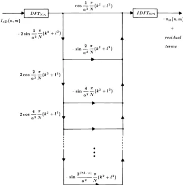
,M1' 2cos 4 rr(k'+1') sin u-rr (k'+l') z r - sin 9 1(k'+l') :V 2(m -n sin a' (k' +l') IDFT,rv -ar(n. m) residual termsFig. 7. Digital implementation of the truncated inverse filter.
degrading the resolution, if its passband is limited to the
passband of the object function. Because of the specific formof the kernel, its band -limited version is also almost space
limited. Thus, once the resolution limit of the object distribu-tion is set, both the sampling rate and the spatial extent of the
filter are known. This information is enough to convert the
continuous system given in Figs. 5 and 6 to a discrete system. For computational efficiency, circular convolutions are used instead of linear convolutions.
The discrete version of the convolution kernel h7(x,y) is
given as
h7(n,m) = Kexp[j
z X2(n2 + m2)]
7r
= Kexp[ja2 (n2 + m2)
where X is the spatial sampling period. The parameter introduced for normalization and is defined as
a2=
X2.N Xz
(38)
a is
(39)
Full discussion of issues related to sampling and discretization
of holograms may be found in Refs. 16 and 17. The discrete
implementation of the truncated inverse filter is shown in Fig. 7.
6. RESULTS
The algorithm shown in Fig. 7 has been implemented in the
image processing laboratory of the Laboratory for Power and Environmental Studies of the State University of New York at
Buffalo. The laboratory is equipped with a Comtal Vision One /20 image processor interfaced with a bank of VAX 11
minicomputers. A TV camera, magnifying lenses, and a light
table are used to input optical holograms. For the following figures, the initial hologram sizes are 256X256 pixels, with
2cosAZL( a 2 N
L>(n.m)
residual terms
Fig. 5. The truncated inverse filter for decoding in-line holograms. Fig. 7. Digital implementation of the truncated inverse filter.
2Az , 2cos (u 2 + v2 ) 2 cos (u 2 + i 1\z . s>n ( residual terms . 2< M - 1 >A2 / _ sm - (« 2 + u 2 )
Fig. 6. The truncated inverse filter in the Fourier transform domain.
The filter shown in Fig. 5 can be represented in the Fourier domain as shown in Fig. 6. The structure given in Fig. 6 for the computation of the filter is more efficient than the direct implementation of Eq. (24). Digital decoding of in-line holo- grams, which suppresses the twin image, is achieved by the digital implementation of the filter shown in Fig. 6. Note that the truncated inverse filter as shown in Figs. 5 and 6 is neither band limited nor space limited. However, because of the linearity of the system, the filter needs to be considered only over the passband of the input. The input can be assumed to be a low-pass function with cutoff frequency determined by the experimental parameters or by the desired resolution. Therefore, the filter of Fig. 5 can be band limited without
degrading the resolution, if its passband is limited to the passband of the object function. Because of the specific form of the kernel, its band-limited version is also almost space limited. Thus, once the resolution limit of the object distribu- tion is set, both the sampling rate and the spatial extent of the filter are known. This information is enough to convert the continuous system given in Figs. 5 and 6 to a discrete system. For computational efficiency, circular convolutions are used instead of linear convolutions.
The discrete version of the convolution kernel hz (x,y) is given as
hz (n,m) = KexpM -^X2 (n2 + m2 )! -(n2 + m2 )! ,
= Kexp j (38)
where X is the spatial sampling period. The parameter a is introduced for normalization and is defined as
- 7T 7T
ot2 — = X2 .
N Xz (39)
Full discussion of issues related to sampling and discretization of holograms may be found in Refs. 16 and 17. The discrete implementation of the truncated inverse filter is shown in Fig. 7.
6. RESULTS
The algorithm shown in Fig. 7 has been implemented in the image processing laboratory of the Laboratory for Power and Environmental Studies of the State University of New York at Buffalo. The laboratory is equipped with a Comtal Vision One/20 image processor interfaced with a bank of VAX 11 minicomputers. A TV camera, magnifying lenses, and a light table are used to input optical holograms. For the following figures, the initial hologram sizes are 256X256 pixels, with
a
ONURAL,
d
i
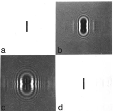
Fig. 8. (a) A computer- synthesized object. (b) Simulated in -line holo-gram of the object of (a); a = 1. (c) Conventional reconstruction by computation from the hologram of (b). (d) Reconstruction from the hologram of (b) using the truncated inverse filter; M = 5.
256 gray levels per pixel. The size of the discrete Fourier
transform pair used for the circular convolutions is 512 X512. Figure 8 shows a computer -simulated in -line hologram of a rectangular object, together with its conventional reconstruc-tion and a reconstrucreconstruc-tion employing the procedure described
in this paper. The reconstruction obtained in Fig. 8(d) is
obtained directly from the hologram of Fig. 8(b) by a
trun-cated inverse filter with M = 5. Profiles of the reconstructions of Figs. 8(c) and 8(d) are shown in Figs. 9(a) and 9(b),
respec-tively. The peak -to -peak level of the background artifact is
reduced by a factor of 8.0 in Fig. 8(d) compared to Fig. 8(c). The reduction is 5 times in the rms sense.
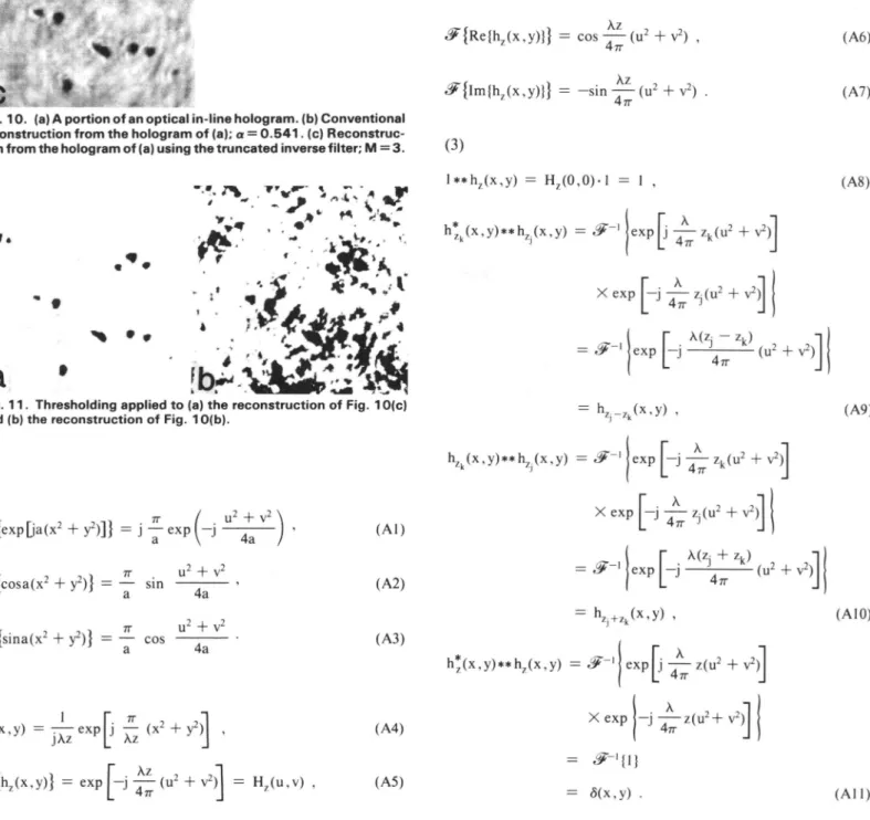
Figure l0(a) shows an optical hologram of deposited parti-cles. The particle size range is 10 to 30 µm, and the recording distance is 1.3 cm. Figure 10(b) is the computer simulation of the conventional reconstruction from this hologram. The same hologram can be reconstructed with approximate inverse filter-ing to suppress the twin image. The result for M = 3 is shown in
Fig. 10(c).
The importance of the reduction of the background artifact
by suppressing the twin image is demonstrated by Fig. I I. Most workers agree that fully automated analysis of in -line
holograms would be desirable. Such automation would
require several processing levels. In the image processing
phase, the hologram is enhanced and decoded in preparation for higher level pattern recognition and analysis. Simple non-linear operations may be used as postprocessors, operating on the results of truncated inverse filtering to complete the image
processing phase. Such nonlinear operations cannot perform well if they are used on images produced by conventional
optical reconstruction. Figure 11 shows the results of simple thresholding to binarize the output images. Figure 11(a) cor-1130 / OPTICAL ENGINEERING / November 1987 / Vol. 26 No. 11
a
Fig. 9. (a) Intensity profile of Fig. 8(c) and (b) intensity profile of Fig. 8(d) along horizontal lines passing through their centers. The ordi-nate is scaled linearly in the gray -level range of the corresponding image, with level 255 (brightest white) at top and level O (black) at bottom. Fill gray -level reverses at level 127. Note the reduced varia-tion surrounding the reconstructed object in (b).
responds to Fig. 10(c), and Fig. 11(b) corresponds to Fig. 10(b). Another simple nonlinear postprocessor is the covar-iance filter for edge detection.lb The result of a cascaded processing of the hologram of Fig. 12(a) by approximate inverse filtering and subsequent edge detection by a
covari-ance filter is shown in Fig. 12(b). This figure summarizes the
work reported in this study. The decoded figure [12(b)] is
obtained from its in -line hologram [ 12(a)] completely by dig-ital means.
7. CONCLUSIONS
Digital and optical data processing techniques have character-istics that are often complementary to each other, stimulating interest in the development of systems combining both digital and optical subsystems. While optical processing offers fast,
massively parallel data acquisition and transformation, the flexibility of digital computation can often be exploited to produce transformations that are nonphysical or at best very difficult to produce in the analog world. Here, such a hybrid
system is employed for optical encoding and digital decoding
of Fresnel or far -field in -line holograms. The intrinsic high
resolution in space and time, depth of field, and robustness of in -line holography remains available, without the usual
lim-itations associated with optical reconstruction. The
advan-tages of digital decoding (twin -image suppression, automated
data reduction, no far -field requirement) must of course be
weighed against the added costs of digital processing. In our experience, these added costs are frequently well compensated for by bypassing the tedious and subjective process of
conven-tional optical reconstructions in many particle and aerosol
applications.
8. APPENDIX: SOME RELATED FORMULAS
In the formulas below, , and
denote the 2 -D Fourierand inverse Fourier transforms, respectively.
ONURAL,:
F ig. 8. (a) A com puter- sy n th esi zed o bject. (b) Si m u I ated in -1 i n e holo- gram of the object of (a); a = 1. (c) Conventional reconstruction by computation from the hologram of (b). (d) Reconstruction from the hologram of (b) using the truncated inverse filter; M = 5.
256 gray levels per pixel. The size' of the discrete Fourier transform pair used for the circular convolutions is 512X512.
Figure 8 shows a computer-simulated in-line hologram of a rectangular object, together with its conventional reconstruc- tion and a reconstruction employing the procedure described in this paper. The reconstruction obtained in Fig. 8(d) is obtained directly from the hologram of Fig. 8(b) by a trun- cated inverse filter with M — 5. Profiles of the reconstructions of Figs. 8(c) and 8(d) are shown in Figs. 9(a) and 9(b), respec- tively. The peak-to-peak level of the background artifact is reduced by a factor of 8.0 in Fig. 8(d) compared to Fig. 8(c). The reduction is 5 times in the rms sense.
Figure 10(a) shows an optical hologram of deposited parti- cles. The particle size range is 10 to 30 jtirn, and the recording distance is 1.3 cm. Figure 10(b) is the computer simulation of the conventional reconstruction from this hologram. The same hologram can be reconstructed with approximate inverse filter- ing to suppress the twin image. The result for M = 3 is shown in Fig. 10(c).
The importance of the reduction of the background artifact by suppressing the twin image is demonstrated by Fig. 11. Most workers agree that fully automated analysis of in-line holograms would be desirable. Such automation would require several processing levels, In the image processing phase, the hologram is enhanced and decoded in preparation for higher level pattern recognition and analysis. Simple non- linear operations may be used as postprocessors, operating on the results of truncated inverse filtering to complete the image processing phase. Such nonlinear operations cannot perform well if they are used on images produced by conventional optical reconstruction. Figure 11 shows the results of simple thresholding to binarize the output images. Figure 1 l(a)
cor-Fig. 9. (a) Intensity profile of cor-Fig. 8(c) and (b) intensity profile of cor-Fig. 8(d) along horizontal lines passing through their centers. The ordi- nate is scaled linearly in the gray-level range of the corresponding image, with level 255 (brightest white) at top and level 0 (black) at bottom. Fill gray-level reverses at level 127. Note the reduced varia- tion surrounding the reconstructed object in (b).
responds to Fig. 10(c), and Fig. ll(b) corresponds to Fig. I0(b). Another simple nonlinear postprocessor is the covar- iance filter for edge detection. 16 The result of a cascaded processing of the hologram of Fig... 12(a) by approximate inverse filtering and subsequent edge detection by a covari- ance filter is shown in Fig. I2(b). This figure summarizes the work reported in this study. The decoded figure [12(b)J is obtained from its in-line hologram [ 12(a)] completely by dig- ital means.
7. CONCLUSIONS
Digital and optical data processing techniques have character- istics that are often complementary to each other, stimulating interest in the development of systems combining both digital and optical subsystems. While optical processing offers fast, massively parallel data acquisition and transformation, the flexibility of digital computation can often be exploited to produce transformations that are nonphysical or at best very difficult to produce in the analog world. Here, such a hybrid system is employed for optical encoding and digital decoding of Fresnel or far-field in-line holograms. The intrinsic high resolution in space and time, depth of field, and robustness of in-line holography remains available, without the usual lim- itations associated with optical reconstruction. The advan- tages of digital decoding (twin-image suppression, automated data reduction, no far-field requirement) must of course be weighed against the added, costs of digital processing. In our experience, these added costs are frequently well compensated for by bypassing the tedious and subjective process of conven- tional optical reconstructions in many particle and aerosol applications.
8. APPENDIX: SOME RELATED FORMULAS
In the formulas below, & and 3F~ l denote the 2-D Fourier and inverse Fourier transforms, respectively.
Fig. 10. (a) A portion of an optical in -line hologram. (b) Conventional reconstruction from the hologram of (a); a = 0.541. (c) Reconstruc-tion from the hologram of (a) using the truncated inverse filter; M = 3.
t
y1 t
J
tA"i O.
441
.
ti
NI t . `t t
a
Eb.4.
...4
. yFig. 11. Thresholding applied to (a) the reconstruction of Fig. 10(c) and (b) the reconstruction of Fig. 10(b).
(1) JF' {exp[Ja(xz + yz)]} J {cosa(xz + y2)} = {sina(x2 + y2)} = (2) hz(x,Y) = exprj j {hz(x,y)} = exp
= j
exp(-j
rr UZ+ vZ z 2 u (Al) (A2) (A3) (A4) (A5)- sin
a 4a 7r Uz + VZ cos a 4a Xz (x2+
y2] Xz-j
4a (u2 + vz) ' = Hz(u,v) ,Fig. 12. Digital decoding of an optical in -line hologram: (a) optical hologram and (b) result of edge detection (output of the covariance filter) applied to the reconstruction using the truncated inverse filter.
Az
{Re{hz(x,y)}} = cos
Orr (uz + y2) ,
{Im{hz(x,y)}} = -sin 4
rr (u2 + y2) .
(3)
1 **hZ(x,y) = Hz(0,0) 1 = I ,
h*zk(x,Y)**hz(x,Y)
= -I
eXPj 4rr zk(uz +vz)[-J À X exp 74-7-r zi(u2 +vz]
r (
zk)_
lexpL j 4rr (uZ v2)] = hZj_Zk(x,Y) , r A hzk(x,Y)**hz(x,Y)= j
' expL
1 Orr zk(u2 + v2)1 [-j X exp j4
zi(uz + vz][
ñ(z + zk)J
= S'-'
exp j 4ir (u2 + vZ) = hr)+zk(x,Y) , X 1h(x,Y)**hz(x,Y) =
4-i
expl
4rr z(u2 + v2)J X exp 1-j 47r z(uz+ vz] = {1}
= S(x,y)
. (A6) (A7) (A8) (A9) (A10) (All)Fig. 12. Digital decoding of an optical in-line hologram: (a) optical hologram and (b) result of edge detection (output of the covariance filter) applied to the reconstruction using the truncated inverse filter.
* 9
«^{Re{hz (x,y)}} = cos (A6)
Fig. 10. (a) A portion of an optical in-line hologram, (b) Conventional reconstruction from the hologram of (a); a = 0.541. (c) Reconstruc- tion from the hologram of (a) using the truncated inverse filter; M = 3.
>*\ ,**
m •*% • *
a '
Fig. 11. Thresholding applied to (a) the reconstruction of Fig. 10(c) and (b) the reconstruction of Fig. 10(b).
(i)
«^{exp[ja(x2 + y2)]} = j y exp f-j
^-^-TT U 2 + V2
= — sin —-——
a 4a
^{sina(x2 + y2)} = — cos
(2)
4a
^{hz (x,y)} - expf-j ^(u2 + v2 )l = Hz (u,v)
(A2) (A3) (A4) (A5) (3) l**hz (x,y) = H2 (0,0)-l = I h*Zk (x,y)**hZj (x,y) = X: = hZj _ 7k (x,y) , h (x,y)**hz.(x,y) = Xexp exP M ~.— Zt(u2 + v2 ) L 47T J [-^¥«2 + v2)]|
r x(zj ^
expL~j ~~^
[zJ+Zk(x 'y).
(A7) (A8) (A9)(u2 + v2;
(AIO)h*(x,y)**hz (x,y) = «^-'
exp
r x ,2
j—-z(u2L 47T
-j-z(u2 +