Acoustical Tuning of CMUT Receiver Arrays
Akif Sinan Taşdelen, Abdullah Atalar, Kerem Enhoş and Hayrettin KöymenDept. of Electrical and Electronics Engineering Bilkent University
Ankara, Turkey 06800 Email: [email protected] Abstract— Cell placement in an element and structural
modifications on the array baffle significantly change the bandwidth, band shape and signal to noise ratio of a CMUT receiver array. In this paper, optimum receiver performance tailoring by means of cell placement, cell size variation and use of dummy cells in the array elements is discussed. The performance of the array is modified acoustically at the acoustic port of the elements.
Keywords—CMUT; array; mutual impedance; acoustical tuning; short circuit receiver current (SCRC) sensitivity; dummy cells
I. INTRODUCTION
Capacitive micro-machined ultrasonic transducer (CMUT) behavior is highly dependent on the medium they are operated in. A very accurate electrical lumped element equivalent circuit approach [1], [2] intensively facilitates the analysis and design procedure for an individual CMUT cell as well as arrays constructed by numerous CMUT cells.
The equivalent circuit model for a single CMUT cell is given in Fig. 1.
Fig. 1. CMUT equivalent circuit model.
The mechanical resonance frequency is heavily dependent on the reactive part of the radiation impedance if the operating
ka is low, like around π/2 as in phased arrays. The reactance of
the series branch is 𝑋𝑠= 1 𝜔 𝐶𝑚+ 𝜔𝐿𝑚+ 𝑋𝑅 (1) where 𝑋𝑅= 𝜋𝑎2𝑐0𝜌0𝑋1(𝑘𝑎) (2) and 𝑋1 𝑘𝑎 = 𝐻1(2𝑘𝑎 ) 𝑘𝑎 (3)
where H1(x) is the Hänkel function of the 1st order, a is the cell
radius, k is the wavenumber, c0 and ρ0 are the sound speed in water and density of water respectively. For a silicon1 wafer
CMUT with a radius of 15µm, radiating plate thickness 2.05µm, Cm and Lm are calculated to be 6.14µF and 3.43pH respectively. Without the radiation reactance this would result in a resonance at fs=34.7MHz. Together with XR however the series resonance drops to 19.9MHz.
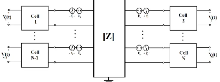
When an array of these cells are constructed the impedance
ZR becomes a matrix Z (Fig 2), which incorporates the self radiation impedance the individual cell faces against due to the medium as well as over-the-medium-coupled interaction between adjacent cells, Zij [3].
Fig. 2. N cell CMUT Array equivalent circuit model.
The acoustic force on each cell in the array can be expressed as the following matrix relation:
𝐹1 𝐹2 ⋮ 𝐹𝑁 = 𝑍11 𝑍21 𝑍21 𝑍22 ⋯ 𝑍𝑁1 ⋯ 𝑍𝑁2 ⋮ ⋮ 𝑍𝑁1 𝑍𝑁2 ⋱ ⋮ ⋯ 𝑍𝑁𝑁 𝑣1 𝑣2 ⋮ 𝑣𝑁 (4)
where Fi and vi represent the force and particle velocity respectively. The diagonal elements are the self radiation impedances and the off diagonal elements, which are symmetric, represent the mutual impedances between the corresponding cells.
1 For Silicon, Young’s modulus of 148 GPa, Poisson’s ratio of 0.17 and a
density of 2370 kg/m3 has been taken
II. OPEN CIRCUIT VOLTAGE RESPONSE VERSUS SHORT CIRCUIT CURRENT RESPONSE
A 2×128 CMUT receiver array is modeled and simulated in Advanced Design System (ADS). Cell radii are chosen as 80% of λ/4 at 20MHz, i.e., 15μm. The radiating plate thickness is chosen to be 2.05μm to have peak array sensitivity at 20MHz. Simulations are performed with various gap heights ranging from 30nm to 300nm. In each case, the CMUTs have been biased with 80% of their respective collapse voltages under 1atm static pressure. CMUTs are assumed to be lossless.
In the first set of simulations the electrical termination of the individual CMUT cells are kept open circuit and the voltage across the terminals are divided to the incident pressure at the acoustical port to obtain the open circuit receiver voltage response (OCRV) of the cell. Fig. 3 shows the OCRV versus frequency of a single cell located in the middle of the array for various gap heights. It is shown that OCRV increases with larger gap height, which requires higher biasing voltage.
In the second set of simulations the electrical termination is shorted to the ground and the current per 1μPa input pressure is observed as short circuit receiver current response (SCRC). Fig. 4 shows the SCRC versus frequency of a single cell located in the middle of the array for various gap heights. It is shown that the SCRC increases with smaller gap height, which requires a lower biasing voltage.
Fig. 3. Open circuit voltage response of a single CMUT cell
Fig. 4. Short circuit current response of a single CMUT cell
Low biasing voltage is a substantial design advantage in respect to CMUT and front-end electronics. CMOS manufacturing is typically a low voltage process, limited at best by several tens of volts. A successful CMUT to frontend integration can only be achieved with CMUTs requiring low voltages for operation.
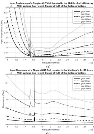
The monitoring of short circuit current necessitates the usage of a transimpedance amplifier at the electrical terminal of the CMUT to convert the monitored current to voltage. Fig. 5 (a) and (b) show the input resistance and reactance, respectively. For 30nm gap height, the input referred electrical impedance of a single cell is found to be 100kΩ+j40kΩ, or 100kΩ in parallel with a capacitance of 200fF. Thus, a transimpedance amplifier with 100kΩ feedback resistor, or in other words a 100dB transimpedance gain, is needed at the electrical terminal. With such an amplifier, the combined voltage sensitivity at the output will be around −213dBV/µPa for a single cell having an aperture of approximately 700µm2.
(a)
(b)
Fig. 5. (a) (above) Input resistance of a single CMUT cell located in the middle of a 2×128 array. (b) (below) Input reactance of a single CMUT cell located in the middle of a 2×128 array
This number alone does not give much insight to the superior receiver capabilities of CMUT. It has to be compared to the noise due to the radiation resistance that is the dominating noise source, since the cells can be manufactured with almost no loss compared to the acoustic noise [4].
The noise per square root Hz at the acoustic terminal of the transducer is given by
𝑝𝑛 =
4𝑘𝐵𝑇𝑅𝑅
𝑆
(Pa Hz-1/2) (5)
where kB is the Boltzmann constant, T is temperature in Kelvin, RR is the real part of the radiation impedance and S is the aperture of the cell.
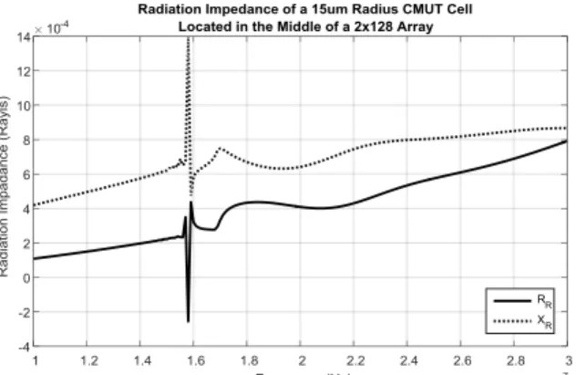
The acoustic radiation impedance of a CMUT cell located in the middle of a 2×128 array is plotted in Fig. 6. Note that the radiation resistance has a zero crossing at 15.8MHz. This is due to the Bloch-Rayleigh resonance [5] at which the cell is “sucked” towards the medium by the negative pressure caused by the other cells of the array. These resonances become insignificant when a loss of 0.03RR is added in series.
Fig. 6. Radiation impedance of a 15µm radius CMUT cell located in the middle of a 2×128 array
The noise pressure amplitude per square-root Hz, or in other words the noise spectral pressure level, is plotted on Fig. 7.
Fig. 7. Noise pressure amplitude per square-root Hz
This spectral amplitude can be converted to spectral noise current (Fig.8) using the short circuit current sensitivity information given on Fig. 3.
Fig. 8. Noise current amplitude per square-root Hz
Note that this is the dominant noise source, for converting the spectral noise current with the transimpedance amplifier having a gain of 100dB the spectral noise voltage will be around 80nV/√Hz at the peak, which is two orders of magnitude larger than the noise levels obtainable with commercial OPAMP amplifiers. Therefore, in this configuration, the SNR limitation is due to the radiation resistance, which is inherent in acoustics of the system, and not the noise contribution of an optimized amplifier.
Integrating this spectral noise over the whole 10 MHz ̶ 30 MHz bandwidth we obtain a total noise current of 1.76nA.
III. CMUTRECEIVER ARRAYS WITH DUMMY CELLS A 2×128 CMUT receiver array is modeled and simulated in Advanced Design System (ADS). Cell radii are chosen as 80% of λ/4 at 20MHz, i.e., 15μm. The baffle between the cells is covered with cavities that have radiating plates on top, but that are not electrically connected (Fig.9). These non-active cells will hereon be referred as dummy cells. For active cells, radiating plate thickness and gap height are 2.05μm and 30nm respectively. Under 1atm atmospheric pressure the collapse voltage of the cells are calculated to be 12.6 V. The biasing voltage of the receiver cells is chosen to be 80% of the collapse voltage, i.e. 10.1 V.
Fig. 9. Array cell configuration with active cells (green) and dummy cells (blue)
The gap height for dummy cells is irrelevant, for they do not have any electrical connection. Their only contribution is mechanical, due to their covering plate. This can be electrically modeled as a series capacitance, for the plate compliance, and an inductor, for the plate mass.
Thus the array model in Fig. 2 can be modified as seen below.
Fig. 10. N cell CMUT equivalent circuit model for an array with N dummy cells.
The effect of dummy cells can be modified by changing their radii and/or plate thickness. In the simulations below the plate thicknesses have been changed from 1.15µm to 2.55µm.
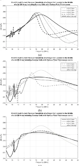
It can be observed from Fig. 11 that by changing the plate thickness of the dummy cell results in a change in active cell response. It can be observed from Fig.11 (a) that dummy cells having thicker plates than active cells, thus having a higher resonance frequency, significantly reduce the bandwidth of the active cells. The amount of bandwidth reduction increases as the thickness difference becomes smaller.
An interesting phenomenon happens, as the plate thickness of the dummy cells is thinner than the active cells’ (Fig.11 (b). At some point where the dummy to active cell thickness ratio becomes 0.75 a flat SCRC sensitivity can be observed. Although the peak SCRC sensitivity drops 3.5dB, the −3dB bandwidth of the SCRC sensitivity increases 2.3 times. Further reducing the plate thickness of the dummy cells causes the SCRC sensitivity to approach its shape without dummy cells.
(a)
(b)
(c)
Fig. 11. Short circuit current receiver sensitivity of a single Cell Located in the Middle of a 2×128 Array Including Dummy Cells with Various Plate Thicknesses
To compare the sensitivity performance of an array with dummy cells with other possible element configurations, short circuit current reception sensitivities of four different cases have been simulated. In the first case, a 2×128 array, where elements consist of a single cell with a radius of 0.8λ/4 is constructed and the remaining baffle surface is taken as rigid (referred to as rigid in Fig. 12). In the second case, a 2×128 array is constructed with the same cell radius as in the first case, however inter-cell spaces are covered with additional cells. In this configuration one element in the array consists of 2 diagonal cells. In the third case, the inter-cell space is filled
with dummy cells that have 24% thinner plates and are not electrically connected. Here, one element consists of an active and a dummy cell. In the last case, the same geometry as in the first case is repeated with larger cells, i.e. a=0.9λ/4. Note that all cases have the same unit area. The results are depicted in Fig. 12.
Fig. 12. SCRC sensitivity of a single element in various formations. As expected, larger cells (case4) result in higher received signal as compared to case1. Note that having more cells of the same geometry does not increase the sensitivity by 6dB, and what’s more interesting, it shifts the sensitivity peak to a higher frequency. This is due to the fact that the reactive part of the mutual impedance of the whole array has been changed. Having off-tuned dummy cells reduces the peak sensitivity (but note that it is not reduced to half), however it results in a wider bandwidth with respect to 1st and 4th cases, without
changing the center frequency as in the 3rd case. The response
is flatter with a sharp drop at the lower band, where the Rayleigh-Bloch waves exist.
IV. CONCLUSIONS
Having different structures instead of a rigid baffle in a CMUT array significantly changes the reception behavior of the operating cells, due to mutual acoustic coupling. Introducing non-active cells, which consist of a plate over a cavity in between the active cells, and tuning them can result in wider receiver bandwidth for the active cells at a cost of reduced peak sensitivity.
ACKNOWLEDGEMENT
This work was supported by the Scientific and Technological Research Council of Turkey (TUBITAK) under project grant 113E031.
REFERENCES
[1] H. K. Oguz, S. Olcum, M. N. Senlik, V. Tas, A. Atalar, and H. Koymen, “Nonlinear modeling of an immersed transmitting capacitive micromachined ultrasonic transducer for harmonic balance analysis,” IEEE Trans. Ultrason. Ferroelectr. Freq. Control, vol. 57, no. 2, pp. 438– 447, 2010.
[2] H. Koymen, et al., “An improved lumped element nonlinear circuit model for a circular CMUT cell,” IEEE Trans. on Ultrason., Ferroelec. and Freq. Cont., vol. 59, no. 8, pp. 1791–1799, August 2012.
[3] H.K. Oguz, A. Atalar and H. Koymen "Analysis of mutual acoustic coupling in CMUT arrays using an accurate lumped element nonlinear equivalent circuit model" Proc. IEEE Ultrasonics Symp. 2012. [4] A. Unlugedik, A.S. Tasdelen, A. Atalar, and H. Koymen, “Designing
efficient CMUT cells for airborne applications”, Proc. IEEE Ultrasonics
Symp. 2014.
[5] A. Atalar, “Rayleigh Bloch waves in CMUT arrays,” IEEE Trans. Ultrason. Ferroelectr. Freq. Control, vol. 61, no. 12, pp. 2139–2148, 2014.