BaOx/ Pt(111) AND BaOx/ TiO2/ Pt(111) MODEL CATALYSTS
FOR UNDERSTANDING NOx STORAGE-REDUCTION (NSR)
CATALYSIS AT THE MOLECULAR LEVEL
A THESIS
SUBMITTED TO THE DEPARTMENT OF CHEMISTRY AND
THE GRADUATE SCHOOL OF ENGINEERING AND SCIENCE
OF
BILKENT UNIVERSITY
IN PARTIAL FULFILLMENT OF THE REQUIREMENTS
FOR THE DEGREE
OF
MASTER OF SCIENCE
by
EMRE EMMEZ
ii
To My Family
And
iii
I certify that I have read this thesis and in my opinion it is fully adequate, in scope and quality, as a thesis of the degree of Master of Science
___________________________________ Asst. Prof. Emrah ÖZENSOY (Supervisor)
I certify that I have read this thesis and in my opinion it is fully adequate, in scope and quality, as a thesis of the degree of Master of Science
___________________________________ Prof. Dr. Şefik SÜZER
I certify that I have read this thesis and in my opinion it is fully adequate, in scope and quality, as a thesis of the degree of Master of Science
___________________________________ Asst. Prof. Coşkun KOCABAŞ
iv
I certify that I have read this thesis and in my opinion it is fully adequate, in scope and quality, as a thesis of the degree of Master of Science
_________________________________ Asst. Prof. Hande TOFFOLI
I certify that I have read this thesis and in my opinion it is fully adequate, in scope and quality, as a thesis of the degree of Master of Science
___________________________________ Asst. Prof. Daniele TOFFOLI
Approved for the Graduate School of Engineering and Science
____________________________________ Prof. Dr. Levent ONURAL
v
ABSTRACT
BaOx/ Pt(111) ANDBaOx/ TiO2/ Pt(111) MODEL CATALYSTS
FOR UNDERSTANDING NOx STORAGE-REDUCTION (NSR)
CATALYSIS AT THE MOLECULAR LEVEL
EMRE EMMEZ
M.S. in Chemistry
Supervisor: Assistant Prof. Dr. Emrah ÖZENSOY August 2011
In this work, formation anddecomposition pathways of of Ba(NO3)2 on
BaO-BaO2 /Pt(111) surfaces were investigated at the molecular levelfordifferent
BaO-BaO2coverages starting from small 2D islands of 0.5 MLE (MLE: monolayer
equivalent) to thick multilayers of 10 MLE via temperature-programmed desorption (TPD), and X-ray Photoelectron Spectroscopy (XPS) and Low Energy Electron Diffraction (LEED). BaOxoverlayerswith a surface coverage of ~ 1 MLEreveallong
range ordering with (2×2) and/or (1×2) structures while BaOx films with a surface
coverage of1.5 MLEyields aBaO(110) termination and thicker films ( ≥ 5 MLE) were observed to be amorphous. Saturation of thick (10 MLE) BaOxoverlayers with
NO2 leads to the formation of nitrates. Nitrate thermal decomposition was
demonstrated to proceed through nitrite intermediates. In TPD experimentstwo major pathwaysfornitrate decomposition were observed: 1) nitrate decomposition yielding only NO evolutionat ~650 K, and 2) nitrate decomposition withNO + O2evolutionat
~700 K. This multi-step decomposition behavior was explained by BaO2 formation
during the first stage. The influence of the BaOxdeposition method on the
morphology of the BaOxoverlayers were established: when a thick BaOx layer is
vi
substrate forming a well-dispersed film. On the other hand, ifa thick BaOx layer is
heated in O2 (to 873 K), BaOx overlayer agglomerates into 3D clusters, resulting in
the formation of exposed (uncovered) Pt sites. BaOxoverlayers with uncoveredPt
sitescan be “cured” by nitration – thermal decomposition procedures. When the BaOx
layer coverage is below 2.5 MLE, nitrate decomposition temperature is observed at significantly lower temperatures, demonstrating the catalytic influence of the Pt sites facilitating the nitrate decomposition. It is proposed that initially, Ba(NO3)2
decomposesatthe boundary/peripheralsites of the Pt/BaOx interface, followed by the
nitrate decomposition originating from 2D BaOx islands, and eventually from the 3D
BaOx agglomerates.
Catalytic deactivation of TiO2-promoted NOx-storage reduction (NSR)
catalysts due to thermal aging effects was investigated using a BaO/TiO2/Pt(111)
model catalyst system. At room temperature, metallic Ba overlayers on TiO2/Pt(111)
was found to be very reactive towards oxide ions on TiO2/Pt(111) resulting in the
formation of BaOx and partial reduction of TiO2. Ba films adsorbed on TiO2/Pt(111)
that are further oxidized in O2 at 523 K lead to BaO and BaO2 surface domains which
can efficiently adsorb both NO2 and CO2. Thermal treatment of
BaO-BaO2/TiO2/Pt(111) surface at T ≥ 300 K leads to a monotonic decrease in the
surface Ba/Ti atomic ratio indicating the diffusion of BaO-BaO2 domains into the
underlying TiO2 framework. Solid state reactions between BaOx and TiO2
particularly within 473-873K facilitate the formation of BaTiO3/Ba2TiO4/BaxTiyOz
overlayers. After oxidation at higher temperatures (T > 873 K), surface becomes Ba-deficient and the enrichment of the surface with the Ti4+ sites results in a TiO2
-terminated surface. Diffusion of BaOx into the TiO2 matrix and the enrichment of the
surface with Ti sites drastically suppress the NO2 and CO2 adsorption/storage
capacity of the model NOx storage system. These results reveal a direct evidence for
the structural changes associated with the thermal deactivation of TiO2-promoted
NSR catalysts.
Key Words: NSR, model catalyst, BaO thin films, TiO2 thin films, NO2, UHV,
vii
ÖZET
NO
xDEPOLAMA-İNDİRGEME KATALİZ İŞLEMİNİN BaO
x/
Pt(111) ve BaOx/ TiO2
/ Pt(111) MODEL KATALİZÖRLERİ
YARDIMIYLA MÖLEKÜLER DÜZEYDE ANLAŞILMASI
EMRE EMMEZ
Kimya Bölümü Yüksek Lisans Tezi Tez Yöneticisi: Yard. Doç. Emrah ÖZENSOY
Ağustos 2011
Bu çalışmada, daha önceden kurulumu tamamlanmış olan çok amaçlı yüksek ötesi vakum sistemine, BaOx/ Pt(111) model NOx depolama/indirgeme katalizör
üretimi amaçlanarak, Pt(111) yüzeyi üzerinde farklı miktarlarda büyütülen BaOx
filmlerinin NO2(g) türüyle olan etkileşimi Sıcaklık Programlı Yüzey Salınımı (TPD)
ve X-Ray Photoelectron SpectroscopyX-ışını fotoelektron spektroskopisi (XPS) yöntemleriyle incelenmiştir. BaOx birimlerinin Pt(111) tek-kristal numunesine
dozlanmasıyla oluşan düzenli yapılar, Düşük enerjili electron kırınımı (LEED) yöntemiyle incelenmiştir. Buna göre Pt tek-kristali üzerinde büyütülen ~1 MLE (MLE: eşdeğer tek katman) yüzey derişimine sahipBaOx filmlerinde (2x2) ve (1x2)
yeniden-yapılanmaları gözlemlenmiştir. Dozlanan BaOx miktarına bağlı olarak
oluşan düzenli yapılar birbirinden farklılık göstermektedir. Örneğin ~1.5 MLE yüzey derişimine sahip BaOx filmleri, BaO(110) yüzey yapılanması sergilemesine rağmen,
5 MLE’den dahayüksek kalınlığa sahip BaOx filmlerinde atomic düzeyde düzenli bir
yüzey yapısı yerine amorf bir yapı gözlemlenmiştir. Kalın tabaka halinde büyütülen (10 MLE) BaOx birimlerinin NO2(g) ile yoğun etkileşimi sonucunda öncelikle nitrat
oluşumu gözlemlenmiştir. Yüksek sıcaklıklarda nitratların parçalanmasıyla, nitrit türlerinin oluşumu gözlemlenmiştir.TPD çalışmalarına göre, nitratlar iki adımda
viii
bozunmaktadır 1) ~650 K’desadece NO yüzey salınımı ile ve 2) ~700 K’de NO + O2yüzey salınımı ile.İlk adımdaki NO yüzey salınımı sırasında, BaO2 oluşumu
saptanmıştır.BaOxfilmlerininfarklı hazırlanış yöntemlerinebağlı olarak, yüzey
morfolojileri de değişkenlik göstermektedir. Buna göre O2(g) içerisinde 873 K’de
ısıtılan BaOx/ Pt(111) model katalizörünün oda sıcaklığında NO2(g) adsospsiyonu
sonucunda yapılan TPD deneyinde, N2 yüzey salnımına rastlanmıştır. N2(g) gazının
yüzeyden salınımı,BaO birimlerinin Pt yüzeyini yeterince kaplamadığına ve Pt tek kristalinin NO2(g) gazıyla tepkimeye girip, NO2(g) gazını, N2(g) gazına
indirgediğine işaret etmektedir. BaOx filmlerinin NO2(g) ile etkileşimi sonucu oluşan
nitratların kararlılıkları, farklı yüzey kaplama kalınlıklarınabağlı olarak değişiklik göstermektedir. Hazırlanan kalın filmlerde (10 MLE) oluşan nitratlar, ince filmlerde gözlemlenen nitratlara göre (~1 MLE) ısıl olarak daha kararlıdır.NOx-indirgeme
depolama malzemelerine TiO2 ilavesinin, bu malzemelerin ısılyaşlanmalarına olan
etkisini incelemek için, BaO/ TiO2/Pt(111) model katalizör sistemi hazırlanmıştır.
Oda sıcaklığında, metalik Ba birimlerinin TiO2/Pt(111) yüzeyi üzerine dozlanması
sonucu, TiO2 filmlerinin kısmen indirgendiği gözlemlenmiştir. TiO2/ Pt(111) yüzeyi
üzerinde büyütülen Ba birimlerinin O2(g) içerisinde 523 K’de oksitlenmesi, NO2(g)
ve CO2(g) türleriyle etkili bir şeklide reaksiyona giren BaO ve BaO2 türlerinin
oluşmasını sağlamıştır. BaO-BaO2/TiO2/Pt(111) model katalizörünün 300 K’den
daha yüksek bir sıcaklıkta ısıtılması, BaO-BaO2 oksitlerinin TiO2 alttaş örgüsünün
içine nüfuz etmesine neden olmaktadır. 473K- 873K sıcaklıkları arasında ise, BaOx
birimlerinin TiO2 ile tepkimeye girmesiyle,BaTiO3/ Ba2TiO4/ BaxTiyOz
perovskit-türü yapıları oluşturdukları gözlemlenmiştir. T>873 K’de, Ba birimlerinin artan yüzey-altı difüzyonu nedeniyle, yüzeydeki TiO2 oranının zenginleştiği
görülmektedir. TiO2 ile zenginleştirilmiş/örtülmüş BaOx/TiO2/Pt(111) model
katalizör yüzeyinin, NO2 ve CO2 gaz türleriyle olan etkileşim kuvveti ciddi şekilde
azalmaktadır.
Anahtar Kelimeler: NSR, model katalizör, BaO ince filmleri, TiO2 ince filmleri,
ix
ACKNOWLEDGEMENT
I would like to thank to;
... Assistant Prof. Dr. Emrah Özensoy for his outstanding guidance, encouragement and supervision throughout my studies…
... Dr.Evgeny Vovk for his contribution to my scientific background…
…Prof. Mehmet Erbudak from ETH Zurich, for his generous help during the construction of our UHV Suface Analysis Chamber…
... past and present members of Chemistry Department; where I learned a lot and made great friends during the last 7 years...
… the Scientific and Technical Research Council of Turkey (TUBITAK)…
…my parents; Erdener and Temaşa, my sister Merve and my brother Emirhan for their continuous support, prayers and help…
…Finally, I am deeply thankful to Didem, her optimism, energy and unconditional love brought the greatest joy to my life…
x
TABLE OF CONTENTS
1 INTRODUCTION ... 1
1.1 Model Catalysts for Heterogeneous Catalysis under UHV (Ultra High Vacuum) Environment ... 7
1.1.1 Metal Oxide Ultrathin Films on Metal Substrates as Model Catalysts .. 8
1.2 Remediation Studies of NOx on Model Oxide Surfaces ... 12
2 EXPERIMENTAL ... 18
2.1 Ultra-High Vacuum Experimental Set-up ... 18
2.2 UHV Compartments ... 21
2.2.1 Sputtering Ion Gun (LK Technologies NGI3000 Sputtering Gun) ... 21
2.2.2 Precision XY-Z Manipulator Platforms (McAllister MC1500/2000) .. 23
2.2.3 Thin Film Doser Compartment ... 25
2.2.4 Temperature Controller (Heat Wave Labs Model 101303-46A) ... 27
2.3 Surface Analytical Techniques ... 28
2.3.1 XPS (X-Ray Photoelectron Spectroscopy) ... 28
2.3.2 Low Energy Electron Diffraction (LEED) Technique ... 35
2.3.3 Temperature-Programmed Desorption (TPD) ... 42
2.4 Sample Preparation ... 44
2.4.1 Sputtering of the Sample ... 44
2.4.2 Preparation of BaOx Overlayers on Pt (111) and also on TiO2/Pt (111) Surfaces ………...45
3 RESULTS and DISCUSSION ... 48
3.1 BaO Films Grown on Pt (111) Substrate ... 48
3.1.1 Structure of BaO Layers on Pt (111)... 48
xi
3.1.3 Effect of the BaOx Preparation Protocol on the Surface Morphology
and Chemistry ... 58
3.1.4 NO2 Adsorption on Thin BaOx Layers ... 62
3.2 TiOx Films Grown on Pt (111) ... 68
3.3 BaO Films on TiO2/Pt (111) Model System ... 71
3.3.1 XPS Analysis of BaO/ TiO2/ Pt (111) Model Catalysts ... 71
3.3.2 LEED Analysis of the Structural Changes of the BaOx/ TiO2/ Pt(111) Model Catalyst ... 75
3.3.3 Chemical Reactivity of BaOx/BaxTiyOz Overlayers to NO2 and CO2 on TiO2/Pt(111) Model Catalyst ... 77
4 CONCLUSIONS ... 84
5 APPENDIX ... 86
5.1 Pumping Units ... 86
5.1.1 Rotary Pumps ... 86
5.1.2 Turbo molecular Pump ... 88
5.1.3 Titanium Sublimation Getter Pumps ... 89
5.2 UHV Pressure Gauges ... 90
5.2.1 Ionization Gauge ... 90
5.2.3 Thermal Conductivity Gauge (Thermocouple Gauge) ... 92
5.2.4 Capacitance Manometer ... 92
5.3 XPS Figures ... 94
xii
LIST OF TABLES
Table 1. Typical exhaust gas composition of a gasoline powered spark ignition
internal combustion engine.[1]... 1
Table 2. European Union emission standards for gasoline and diesel powered (within
bracket) passenger cars (g km-1)[4] ... 3
Table 3. Pressure Ranges for Vacuum Technologies. ... 19 Table4. The relationship between quantum numbers, spectroscopists’ notation and
X-ray notation.[67] ... 29
xiii
LIST OF FIGURES
Figure 1. NOx Storage and Reduction, (a) representation of mechanism and (b)
representation of lean and rich cycles [5] ... 5
Figure 2. Development of supported model catalysts and comparison of the
preparation techniques (adapted from ref.[27]) ... 9
Figure 3. Structural parameters and kinetic effects on supported metal catalysts
(adapted from ref.[27]) ... 10
Figure 4. Thermal desorption spectra of NO on NiO (100) cleaved in vacuum (upper
left) and NO on a thin NiO (100) film grown by oxidation of NiO (100) (lower left). Thermal desorption spectra of CO on NiO (100) cleaved in vacuum (upper right) and CO on a thin NiO (100) film grown by oxidation of Ni (100) (lower right) [36] ... 11
Figure 5. Molecular orbital diagrams of NO and NO2 [37] ... 12
Figure 6. The visual representations of multi-technqiue UHVsurface analysis
chamber. ... 21
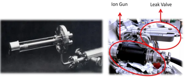
Figure 7.LK technologies sputtering ion gun with a high-precision leak valve. ... 22 Figure 8. The MC1500/2000 series XY translator with manual micrometer
controllers. ... 23
Figure 9. (a) The ZA-series Z-axis translator (b) currently used complete XYZ-θ
manipulator including a DC motor used (c) the visual representation of the manipulator probe. ... 24
Figure 10. Differentially-pumped-rotary-platform (rotary seal) used in manipulator
part... 25
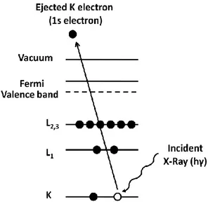
Figure 11. Thin film doser compartment and types/locations of particular dosers. .. 26 Figure 12. Sample temperature controller unit used in UHV chamber. ... 27 Figure 13. Schematic diagram of the XPS process that demonstrates the
photoionization of an atom by ejection of a 1s electron. (adapted from ref. [67]). ... 30
Figure 14. Schematic diagram of the cylindrical mirror analyzer (CMA). (adapted
from ref. [67])... 31
Figure 15. Ba3d and Pt4f XPS spectrum were taken during growth of 10 MLE BaOx
xiv
Figure 16. Bragg’s diffraction condition (adapted from ref. [72]). ... 35 Figure 17. Schematic representation of Low Energy Electron Diffraction Technique.
... 36
Figure 18. Diffraction patterns of five plane lattices. [73] ... 38 Figure 19. Experimental set-up for Temperature Programmed Desorption (TPD)
technique in ultra-high vacuum. (adapted from ref.[68]) ... 42
Figure 20. Sample preparation method P1 for the BaOx films grown on Pt (111)
substrate (Protocol 1). ... 45
Figure 21. Sample preparation method P2 for the BaOx films grown on Pt (111)
substrate (Protocol 2). ... 46
Figure 22. Sample preparation method for the BaOx films grown on TiO2/Pt (111)
model system. ... 47
Figure 23. LEED pictures obtained during various stages of the ordered BaOx
overlayer formation on Pt(111) (see text for details). Electron beam voltage for the LEED patterns given in (a-f) is 70-85 eV, respectively. XPS spectrum corresponds to the LEED pattern given in Figure 23b. ... 48
Figure 24. Schematic representations of the LEED patterns given in Figure 23.
Large (black) diffraction spots correspond to the Pt(111) substrate while small (red and black) diffraction spots originate from the overlayer (a) (2x2)R30o superstructure (b) (1x2)R30o superstructure (c) (2x2) superstructure (d) (1x2) superstructure. Tentative real space representations of the (e) (2x2) and (f) (1x2) superstructures... 50
Figure 25. (a) LEED patterns for a BaOx (1.5 MLE)/Pt(111) surface and (b) the
schematic representation of the corresponding diffraction spots. Big black spots correspond to the Pt(111) substrate while the small black spots correspond to three different rotated domains with real-space unitcell dimensions of 3.9×5.5 Å . ... 52
Figure 26. XPS core level spectra, N1s and O1s for a thick BaOx(10 MLE) /Pt(111)
exposed to 3600 L NO2 at 323 K and subsequently annealed to the indicated
temperatures in vacuum. ... 54
Figure 27. TPD spectra for NO (m/z= 30), O2 (m/z=32), and N2/CO (m/z=28)
channels obtained after exposure of BaOx(10 MLE)/ Pt(111) surface to 900 L NO2 at
323 K. ... 57
Figure 28. (a) TPD spectra for the NO (m/z=30), O2 (m/z=32), and N2/ CO (m/z=
xv
surface to 900 L NO2 at 323 K; where the BaOx film was prepared using protocol 2
(b) A similar TPD experiment performed on a BaOx(10 MLE)/ Pt(111) surface which
was initially exposed to subsequent multiple cycles of NO2 adsorption/saturation and
annealing at 1073 K. ... 60
Figure 29. O1s XPS core level spectra for BaOx(~2.5 MLE) /Pt(111) surface
exposed to 360 L NO2 at 323 K and subsequent annealing to the indicated
temperatures. ... 63
Figure 30. The graphs of O1s peaks intensity ratios Operox (530.8 eV) to Oox (528.6
eV) for 10 ML (grey squares) and 2.5 ML (black circles) BaOx films measured after
nitration and subsequent heating. ... 64
Figure 31. TPD spectra for NO (30 amu), O2 (32 amu), and N2/CO (28 amu)
obtained after exposure of BaOx(~2.5 MLE) /Pt(111) to 900 L NO2 at 323 K. ... 65
Figure 32. TPD spectra for NO (30 amu), O2 (32 amu), obtained after exposure of
BaOx(~2.5 MLE) /Pt(111) to 900 L NO2 (PNO2= 5x10⁻⁷ Torr x 30 min) at 323 K then
preheated to 623 K before TPD. ... 66
Figure 33. TPD spectra for NO (30 amu) desorption obtained after exposure of
BaOx/ Pt(111) surfaces with varying BaOx coverages (0.5 MLE < θBaOx<10 MLE)
to 900 L NO2 (PNO2= 5x10⁻⁷ Torr x 30 min) at 323 K. ... 67
Figure 34. XPS spectra of TiOx phases depending on the oxidation conditions in the
Ti2p and O1s core level region (see text for details). ... 69
Figure 35. LEED patterns for ordered TiOx/ Pt(111) surfaces with varying θTiOx (see
text for details) . ... 70
Figure 36. XPS data corresponding to the (a) Ti 2p, (b) O 1s and (c) Ba 3d5/2
regions obtained for (i) TiOx(1.4 MLE)/ Pt(111), (ii) TiO2(26MLE)/ Pt(111), (iii) as
deposited Ba(3 MLE)/ TiO2(26 MLE)/ Pt(111) surface prior to oxidation, (iv)
BaOx(6 MLE)/ TiO2 (26 MLE)/ Pt(111) surface obtained after oxidizing sample (iii)
in O2 (PO2= 5x10⁻⁷ Torr) at 523 K followed by a second Ba deposition at RT and
oxidation at 523 K, (v) a surface prepared by the oxidation of sample (iv) in O2 (PO2=
5x10⁻⁷ Torr) at 973 K. (for Pt4f region see Appendix) ... 72
Figure 37. Ba/Ti surface atomic ratio values obtained from the XPS data for a
BaOx(0.7 MLE)/TiO2(26 MLE)/Pt(111) surface after oxidation and thermal aging
xvi
Figure 38. (a) LEED image corresponding to the (2x2) reconstruction of TiO2 (26
MLE) overlayers on Pt(111), (b) BaOx(0.7 MLE)/TiO2(26 MLE)/Pt(111), (c) a
surface obtained by the oxidation of the sample given in (b) in O2 (PO2= 5x10⁻⁷ Torr)
at 1073 K. Electron energy values used for the acquisition of the LEED patterns in (a-c) were 85 eV, 85 eV and 105 eV, respectively. ... 76
Figure 39. TPD spectra for NO (m/z= 30), N2/CO (m/z= 28) and N2O/CO2 (m/z=
44) desorption channels obtained (a) after exposure of BaO(<1 MLE)/TiO2
(26MLE)/ Pt(111) to 180 L NO2 at RT (b) exposure of BaO(1 MLE< x <2
MLE)/TiO2 (26 MLE)/ Pt(111) to 180 L NO2 at RT (c) exposure of BaO(>2
MLE)/TiO2 (26 MLE)/Pt(111) to 180 L NO2 at RT ... 78
Figure 40. (a) m/z=30 desorption channels in the TPD profiles for NO2 adsorption
(PNO2=1x10⁻⁷, 30 min at RT) on: fresh BaOx(6 MLE)/ TiO2(26 MLE)/ Pt(111)
surface (spectrum i), BaOx(6 MLE)/ TiO2(26 MLE)/ Pt(111) surface pretreated at
973 K (spectrum ii), fresh TiO2(26 MLE)/ Pt(111) surface (spectrum iii). (b) m/z=44
desorption channels for the same TPD experiments given in part (a). (c) m/z=44 desorption channels in the TPD profiles for CO2 adsorption (PCO2=5x10⁻⁷ for 5 min at
RT) on: fresh BaOx(6 MLE)/ TiO2(26 MLE)/ Pt(111) surface (spectrum i), BaOx(6
MLE)/ TiO2(26 MLE)/ Pt(111) surface pretreated at 973 K (spectrum ii). ... 80
Figure 41. Schematic representation elucidating the surface segregation and
sub-surface diffusion in BaOx/ TiO2/ Pt(111) model catalyst systems. ... 83
Figure 42.Sectional view of the Pfeiffer DUO-35, 35 m3/h double stage, rotary vane pump: (1) intake (2) filter (3) rotor (4) spring (5) vane (6) gas ballast valve (7) filter (8) discharge valve (9) exhaust (10) sealing surface.[63] ... 86
Figure 43.Schematic representation of the cross section of a dual-stage RVP
(left)[63] RVP units in the UHV set-up (right). ... 87
Figure 44.Varian TV 551 Navigator-Model 9698923 TMP. ... 88 Figure 45.Titanium sublimation pump unit... 89 Figure 46. (a) Ionization gauge mechanism (adapted from ref. [49]) (b) Schematic
representation of an Bayard-Alpert type ionization gauge (adapted from ref. [63]) (c) Ionization gauge utilized in the UHV set-up... 91
Figure 47.Thermocouple gauges in the UHV experimental set-up. ... 92 Figure 48.(a) Basic diagram of capacitance diaphragm gauges (adapted from ref.
xvii
Figure 49. XPS core level spectra, Ba3d and Pt4f for a thick BaOx(10 MLE) /Pt(111)
exposed to 3600 L NO2 at 323 K and subsequently annealed to the indicated
temperatures in vacuum. ... 94
Figure 50. XPS core level spectra corresponding to Pt4f during the growth of TiO2
1
1
INTRODUCTION
The industrial development in the world leads to an increase in the consumption of fossil fuels such as natural gas, coal and oil. The partial combustion of these compounds results in the emission of nitrogen oxides (NOx), carbon
monoxide (CO), sulfur oxides (SOx), NH3 and also unburned hydrocarbons (HC) to
the atmosphere and cause environmental pollution. These gaseous species also undergo transformations in the atmosphere by oxidation reactions of ozone and also hydroxyl free radicals. Exhaust gas from the combustion of fossil fuels such as petroleum or diesel also contains many pollutants such as NOx, CO, unburned
hydrocarbon and trace amounts of H2, N2O, NH3, CO2 and SOx. However, amount of
NOx produced from diesel engine is less than the gasoline engine since it has a cooler
combustion environment.[1]For a gasoline powered spark ignition internal combustion engine, a typical exhaust gas composition is presented in Table 1.
Table 1.Typical exhaust gas composition of a gasoline powered spark ignition
internal combustion engine.[1]
Exhaust gas pollutant concentration is closelyrelated tothe air to fuel (A/F) ratios:
A/F=mass of air consumed by the engine/mass of fuel consumed by the engine
2
λ = actual engine A/F /stoichiometric engine A/F
For gasoline engines, there is a stoichiometric value for A/F that equals to 14.7.[2] This is the point where the amount of oxidants is equal to that of reducing agents. Fuel-rich condition occurs if the A/F ratio is below this value and in this case, exhaust gas is rich with reducing agents like CO and HC. On the other hand, if A/F ratio is above this value, then it is called the fuel-lean condition and this time the exhaust gas consists of more oxidizing agents like NO and O2.
Hazardous gases emitted from exhausts have devastating effects on earth’s atmosphere, environmentand human health. For instance, NOx is the principal
pollutant for the formation of ground level ozone which is a health hazard and harmful to plants, ozone layer depletion and also acid rains.
It is found that ground level ozone is produced through the photochemical decomposition of NO2 with the following mechanism:[3]
First, the peroxy radicals begin to form with the reaction of CO or hydrocarbons with the hydroxyl radical present in the troposphere:
OH*+ CO H* + CO2 (1)
H*+ O2 HO2* (2)
Peroxy radicals then react with NO to give NO2 and NO2undergoes a further
photochemicalreactionyieldingatomic oxygen which reacts with O2 to give ozone,
O3:
HO2* + NO NO2 + OH* (3)
NO2 + hv (<410 nm) NO + O* (4)
O* + O2 (g) O3 (5)
NOx also catalyzes ozone layer depletion in the stratospheric region via
reactions given below:[3]
NO + O3 NO2 + O2 (6)
3
Finally, NOx form nitric acid when dissolved in moisture of atmosphere:[3]
2NO2 + H2O HNO2 + HNO3 (8)
3HNO2 HNO3 + 2NO + H2O (9)
4NO + 3O2 + 2H2O 4HNO3 (10)
Due to the ecological and health hazards of the NOx and several other
emission gases, regulations have been proposed and enforced to limit NOx
emissions.The type and the level of regulationsvaryamong countries. For instance, European Union emission standards are categorizedas Euro 1, Euro 2, Euro 3, Euro 4 and Euro 5 fuels for light vehicles.Descriptions of European Union emission standards are given Table 2.
Table 2.European Union emission standards for gasoline and diesel powered (within
bracket) passenger cars (g km-1)[4]
The criteria for the compulsive emission limits enforce automotive manufacturers and catalysis researchers to develop more efficient engines and more effective deNOxstrategies. The traditional three-way catalysts (TWC) are ineffective
for NOx treatment under lean operating conditions since TWC technology has been
designedfor the stoichiometric regime (i.e. λ=1).[2]Removal of NOx from lean-burn
exhaust can be performed in three ways: (i) direct thermal decomposition of NO; (ii) selective catalytic reduction (SCR); and (iii) NOx storage and reduction (NSR)
4
agent. (2NO N2 + O2) This is also a thermodynamically favorable process
(ΔHo
298=-86.6 kj/mol).[5]However, veryhigh activation energy is requiredfor the
reaction to proceed. In the second approach, NO can be selectively reduced with variousreducing agents such as H2, hydrocarbons (HC) and NH3/urea in a
rich-oxygen environment. In the case of ammonia SCR, the stoichiometry of the simplified overall reaction is:[6]
4NO + 4NH3 + O2 4N2 + 6H2O (11)
An alternative way for the abatement of NOx species is the NOx
storage-reduction catalysts. NSR catalyst can work under both fuel lean and fuel rich environments. This concept was first introducedby Toyota motor company in the mid-1990s.[7] Under lean conditions of engines (i.e. under excess oxygen) NOx is
adsorbed on the catalyst, while under rich conditions NOx reduction takes place.
Therefore, in an NSR catalyst, there must be sites for both NOx sorption (alkali metal
or alkaline earth metal compounds) and sites for NOx oxidation/reduction (noble
metals).[8]One of the most commonly used NSR catalyst formulation is Pt-Ba/Al2O3.[9]
5
Figure 1.NOx Storage and Reduction, (a) representation of mechanism and (b)
representation of lean and rich cycles [5] 1- Oxidation of NO to NO2 (λ > 1, fuel lean)
2- NOxadsorption on the basic adsorption sites (λ > 1, fuel lean)
3- Release of reducing agents (such as hydrocarbons, CO, or H2) (λ < 1, fuel rich)
4- NOx release from the surface (λ < 1, fuel rich)
5- Reduction of NOx to N2 (λ < 1, fuel rich)
It is found that NO2 adsorbs more effectively than NO to the NSR trapping
material.[10]Therefore, the formation of NO2 is a crucial step for the adsorption, and
the oxidation of NO to NO2 takes place over precious metals. There are two different
6
model is suggested for the NO oxidation over Pt-BaO/Al2O3,[11] second, the
Eley-Rideal type of mechanism is involved for the NO oxidation over Pt.[12]
In literature, there is an ongoing debate associated with the NOx storage
mechanism. In various recent studies,[9,13] it was suggested that NOx storage is
accomplished via different routes (i) the “nitrate route” which involves NO oxidation to NO2 on Pt sites and NO2 spillover to BaO domains yielding the formation
ofBa(NO3)2- and NO(g); (ii) the “nitrite route”, where NO is first oxidized to nitrite
species in the presence of oxygen, followed by oxidation of nitritesto nitrates; (iii)in analternativelyproposed storage mechanism,[14] it is suggested that, NO2 is first
loosely adsorbed on BaO, then these adsorbed species decompose into BaO2 and NO,
and finally BaO2 reacts with NO2(g) to give Ba(NO3)2 as given below;
BaO + NO2 BaO-NO2 (12)
BaO-NO2 BaO2 + NO (13)
BaO2 + 2NO2Ba(NO3)2 (14)
However, there exists soundevidence in the literature that different barium sites can exist, which differ in reactivity.[15,16] The interface between Ba sites and Pt sites are considered to be more reactive than barium sites located further away from Pt.[17]Depending on the reaction conditions, BaO, Ba(OH)2, or Ba(CO)3 can be
formed on the surface. It is also worth mentioning that NOx storage occurs on BaO
more efficiently than Ba(OH)2 and Ba(CO)3.[18]
Under rich conditions, stored NOx is reduced by the reductantssuch as CO,
H2in the following manner.[5, 9]
Ba(NO3)2 + 5CO N2 + BaO + 5CO2 (15)
Ba(NO3)2 + 5H2 N2 + BaO + 5H2O (16)
An additional mechanistic aspect of NSR systems is the SOx poisoning.
Sulfur oxides (SOx) present in exhaust gas can react with the catalyst in a similar way
to the NOx species.[19] Sulfur poisoning can deteriorate catalytic functionality of
both the support material as well as the storage domains. SO2 can form aluminum
7
sulfates are muchhigher than that of nitrates, once sulfates are formed on the catalyst surface, the activity of the catalyst towards NOx species significantly decreases.
1.1 Model Catalysts for Heterogeneous Catalysis
underUHV (Ultra High Vacuum) Environment
In order to promote new catalysts with enhanced performance, it is important to be able to control fundamental surface properties of catalytic materials such as particle size, morphology, chemical composition, dispersionat the atomic level.[20, 21]
From amicroscopic point of view, the relation between real world catalysis kinetics and the elementary reaction mechanisms is generally ambiguous. Thus, fundamental catalyst studies focuse on the well-defined micro kinetic model, in which the reaction mechanisms are properly elucidated[21] in an attempt to relate microscopic properties such as atomic composition, electronic and geometric structure to macroscopic properties such as catalytic activity and selectivity.[22]Real world catalysts are complex materials; most of them are comprised ofmixtures of oxides or sophisticatedmetal/oxide systems. On the other hand the well-defined surface science model catalysts are much more simplistic in terms of their structures creating a so called “materials gap” between surface science and industrial catalysis. [23]In addition, technicalcatalysts are typically operated at elevated pressures (>760 Torr) which is far from the UHV conditions used in surface science studies. This is known as the “pressure gap” between applied catalysis and surface science.[22]
The main advantage of model catalyst systems is that complex morphological and chemical features of a catalyst surface can be introduced in a well-controlled manner using a surface sicence approach. In addition,utilization of metallicsingle crystal support materialsprovide electrical and thermal conductivity which enables the effective use of electron-based spectroscopic (XPS, Auger electron Spectroscopy-AES, Ultraviolet photoemission spectroscopy-UPS, High Resolution electron energy loss spectroscopy-HREELS), diffraction (LEED) and imaging (Scanning Tunneling Spectroscopy-STM) techniques.[24]In these model
8
catalyststudies, a proper selection of metal/oxide interface and the film thickness can be utilized as a design parameter to create novel catalytic materials.[25]
1.1.1 Metal Oxide Ultrathin Films on Metal Substrates as Model
Catalysts
Model catalysts were originally introduced in the late 1960s with the development of UHV technology.Over the years, the complexity for the investigated experimental systemshas continuously increased.Studies on metal single crystal surfaces were the initial starting point providing important reference data for the reactivity of ideal/atomically ordered surfaces and reaction mechanisms.[26]Furthermore, studies on stepped or defect-rich metallic single crystals provided important fundamental knowledge about the catalytic active sites. However, these initially studied simple surfaces did notoften show catalytic properties that are compatible with realistic catalysts. For this reason, more recent studies in surface science focused on more complex model catalysts including oxide surfaces. Here, the surface defect properties of the oxide surfacesturned out to be particularlyimportant due to their direct influence on the reactivity and the growth morphology of the metal deposits (i.e. active sites).[27]Today, a large number of ordered oxide thinfilms such as Al2O3, SiO2, MgO, NiO, Cr2O3, FeO, or Fe3O4 can
be readily prepared via alarge number of precursors.[28]The metal-oxide film growth can be performedby (a) the direct oxidation of a mono-metallic single crystal, (b) the oxidation of a single crystalalloy, (c) the deposition and oxidation of a metal on an inert single crystalsubstrate.[27]Aftergrowth of the metal-oxide thinfilm as the catalytic support material, model catalyst can be modified by deposition of active particles in the form of metal or oxide aggregates in the nanometer size range. Figure 2 represents the general features of the typical model catalysts described above and compares the preparation techniques.
9
Figure 2.Development of supported model catalysts and comparison of the
preparation techniques(adapted from ref.[27])
The earlier work in the literature revealedthat the function of the support is not only limited to the dispersion of the catalytically active sites, but also includes a direct modification of the electronic and structural properties of the active sites.[28] Therefore, the catalytic activity of the model catalyst surfaces is mostly determined by thespecific interplay between the exposed sites. There are several concepts which can relate the surface structural aspectstothe catalytic reactivity.[25]
10
(i) Support Effects:Surface diffusion(such as spillover or
reverse-spillover phenomena) and the adsorption strength of adsorbates on the support material has a strong influence on the catalytic elementary steps.[28,29]
(ii) Size and Electronic Effects:The electronic structure of a
supported metal or metal oxide nanoparticle particle can be different from its planar (single crystal) counterpart. For instance, “size effects” can lead to “electron confinement”. Furthermore, reduced dimensions can cause lattice distortions which can change the electronic environment of the support. [21]It is clear that these kinds of effects are strong mostly for relatively small particles (<5 nm).[30]
(iii) Geometric Effects:A metal particle can exhibit different
specific sites, such as particle edges or corners and these specific sites result in different catalytic activities with respect to a given reaction.[21]
Some of these structural parameters related with the kinetic effects are summarized in Figure 3.
Figure 3.Structural parameters and kinetic effects on supported metal
catalysts(adapted from ref.[27])
The properties of thick films of 5-10 layers are close to bulk materials, however, the properties of ultrathin films with a thickness of 1-5 layers on metallic
11
supports are not always representative ofbulk materials, and can expose properties different from the bulk.[31]MgOwell-ordered oxide films on Mo (100) [34]and also NiO on Ni (100) [35] were grown in order to study oxide film properties with respect to molecular adsorption. In these two specific examples, there is an important misfit between the oxide overlayer and the support, since, mostly defect sites, such as steps and corners interact with adsorbates from the gas phase. If those defect sites were blocked by water adsorption, the properties of the thin film resemble the bulk material.[31] As can be seen from Figure 4, which shows the CO and NO thermal desorption spectra from Ni (100) film and bulk material, the correlation between the data indicates that these thin films may be used to model the surface of the bulk material.[36]
Figure 4.Thermal desorption spectra of NO on NiO (100) cleaved in vacuum (upper
left) and NO on a thin NiO (100) film grown by oxidation of NiO (100) (lower left). Thermal desorption spectra of CO on NiO (100) cleaved in vacuum (upper right) and CO on a thin NiO (100) film grown by oxidation of Ni (100) (lower right) [36]
12
1.2 Remediation Studies of NO
xon Model Oxide Surfaces
The electronic and coordination properties of NOx (x=1, 2) are known and
well-understood. Figure 5 represents the molecular orbital diagrams of NO and NO2.
[37]
Figure 5.Molecular orbital diagrams of NO and NO2 [37]
The bond order in NO is 2.5. It decomposes into its elements only at elevated temperatures in the absence of a catalyst (1100-1200 oC with an activation energy of 335 kJ/mol). NO has an electron in the 2π* orbital and this antibonding electron lowers the dissociation energy of gas phase NO relative to N2. In the case of NO2, the
unpaired electron is more localized on the N atom. The main purpose is to design a catalyst that will decompose NOxinto N2 and O2 efficiently without causing the
production of other nitrogen oxides such as N2O.[37] Therefore, surface science
13
single-crystals, metal oxide single-crystal surfaces and oxide supported metal particles. In the literature, the mechanism of N-O bond breaking on model catalysts has been comprehensively reviewed by Garin.[38]
According to Garin’s review, surface defects with uncoordinated and reactive surface atoms promote the dissociation of the N-O bond on oxide-supported catalysts.During the catalytic reactions of NO decomposition, surface reconstruction phenomena are commonly observed. In addition, adsorption of NOx on metal oxide
surfaces results in several intermediates such as NO2- and NO3-which in turn, can
also alter the oxidation state of metallicsites on the surface.[38]
The mechanism of NO2 storage in magnesium oxide supported barium oxide
(BaO/MgO) has also been investigated by using in-situ Raman spectroscopy and X-ray diffraction in the absence and presence of molecular oxygen.[39] According to these results, up toat T< 400 oC, the NO2 storage behavior in BaO/MgO occurs
through the formation of barium-nitro species which turn into nitrite ions concomitant to the formation of nitrates. At 400 oC, the formation of nitrates is mostly accomplished by BaO2 species. Improvement in the rate of nitrate formation
was observed at low BaO loadings with the presence of oxygen. Stored NO2 can be
reduced by CO and this leads the formation of CO2 which limits the NO2 storage
capacity due to the formation of BaCO3. However, it is also reportedthat these
carbonate species can be replaced by nitrates in the presence of NO2 at 400 oC.
In recent studies, Bowker et al investigated BaO thin films by using Pt (111) as a substrate in order to investigate the NOx storage phenomenon. Their STM
images showed that at relatively low coverages of BaO on the surface, BaOlayers are reconstructed in a (2x2) fashion.[40,41] They have also demonstrated that these BaO particles irreversibly transform into BaO, whereas the BaOthin film partially converts into metastable BaO2 which is lost when the oxygen is removed.[40] BaO
particles do not react with NO at 573 K, however, dosing a mixture of NO and O2
allows the NOx to be stored in the form of nitrate. Moreover, Bowker et al.also
investigated BaO films on a Cu (111) substrate in terms of structure and reactivity. According to their findings, BaO films grown on Cu (111) exhibit a (100) surface orientation and these films can not be readily converted into BaO2 under UHV
conditions.[42] There was no evidence for a reaction between NO and BaO at low NO pressures of within 300 K-573 K, however, NO2 reacted readily with pure BaO
14
at ambient pressures to form nitrite, Ba(NO2)2, then, the slow formation of nitrate
was observed.
Schmitz and Baird et al. studied NO and NO2adsorption on BaO in which
aluminum oxide surface is used as a substrate. The presented data showed that NO adsorbs predominantly as a nitrite and NO2 adsorbs predominantly as a nitrate on
barium oxide during high exposures at room temperature. They proposed that high coverage nitrate forms through the combination of two surface ntrites and a molecularly adsorbed NO2 to form a trimer, in which all nitrogen centers become
nitratelike.[43] They have also reported the occurance of peroxide-like adspecies. They offered an alternative mechanism to the conventional adsorption/reaction of NO2 on BaO. According to this mechanism, the molecular adsorption of NO toform
nitrite-like adspecies dominate the initial trapping mechanism. As NO2 is formed
over the noble metal sites, it can either spill over onto the oxide or dissociatively adsorb to form more nitrites. Furthermore, if the surface coverage of nitrite is high enough, it can alsoform nitrate-like species.
Libuda et al.prepared BaO nanoparticles by Ba deposition and subsequent oxidation on an Al2O3/NiAl (110) support surface and investigated its interaction
with as a function of BaO particle size.[44,45]They have found that immediate intermixing of Ba2+ and Al3+ions along with the formation of a mixed oxide BaAl2xO1+3xoccurs for large film thickness. Moreover, annealing in oxygen enhances
the mixed oxide formation and further growth of the oxide film. Introduction of NO2
on the mixed oxide BaAl2xO1+3x particles on Al2O3/NiAl (110), yields nitrite
formation, and nitrite formation completely saturates at an NO2 exposure of c.a.1000
L (1L: Langmuir = 1x 10⁻⁶ Torr/sec). Beyond this exposure, surface nitrates are generated by the transformation of nitrites into nitrates. By the help of vibrational spectroscopy, they concluded that the surface nitrites and nitrates are primarily coordinated to Ba sites.[45]
Szanyi et al.studied extensively the Ba deposition on a θ-Al2O3/ NiAl (100)
substrate under ultrahigh vacuum conditions and studied the surface species during NO2 exposures to BaO/ Al2O3/ NiAl (100) at different temperatures.[46-50] They
have reported that the preparation of an oxidized Ba deposit by oxidation in O2 at
800 K results in the growth of 2 D and 3 D Ba-containing surface domains, rather than a layer-by-layer growth mode.[46] However, in their previous results, [47] Ba
15
deposition on θ-Al2O3/ NiAl (100) substrate at 300 K in UHV promoted the
layer-by-layer growth of Ba for the first two layer-by-layers. Therefore, they concluded that the growth morphology and the oxidation state of the Ba species on the θ-Al2O3/ NiAl (100)
substrate can be fine-tuned by controlling the preparation conditions such as surface temperature and oxidative environment. NO2 adsorption mechanism on a clean, thick
BaO film supported on Al2O3/ NiAl (110) substrate was also examined.[48]
Accordingly, exposure of BaO to NO2 at 90 K resulted in the formation of
nitrite-nitrate pairs. During the heating of the nitrite-nitrite-nitrate pair covered BaO, nitrites decompose first and leaves one oxygen atom behind which takes a role in the formation of BaO2. The formed BaO2 is present even after all the nitrates are
decomposed. The effect of BaO film thickness on the NOx uptake properties was also
studied, and it was found that the interaction of NO2 with model systems at low BaO
coverages is significantly different from that of a thick BaO film.[49] For instance, nitrite species form at low exposures of NO2, and then nitrates form at high NO2
exposures (>1x 10⁻⁵ Torr). However,for a bulklike, thick (>30 ML) BaO film, NO2
adsorption results in the initial formation of nitri-nitrate ion pairs at low NO2
exposures. The effect of temperature on the nature of NOx species formed was also
identified by the reactionof NO2 witha pure BaO film.[50] The results suggested that
NO2 adsorption on the clean, thick BaO film at 300 K sample temperature leads to
theformation of nitrite-nitrate ion pairs as in the case of 90 K adsorption of NO2.
TiO2 is commonly utilized as a support material in many catalytic process or
as an active catalyst in photocatalytic systems. In the NSR catalysts concept, TiO2
has a noticeable ability to suppress the sulfur deposition.[51] Although, numerous efforts have been done for the sol-gel application of TiO2 in the powdered samples,
there is little known about the chemistry of TiO2 towards NOx species in surface
science applications. Rodriguez et al. investigated the NO2 interaction with TiO2
(110) rutile surface both experimentally and theoretically.[52] According to these results, the main product of the adsorption of NO2 on TiO2(110) is surface nitrate
with a small amount of chemisorbed NO2. Photoemisson data and density functional
theory (DFT) calculations indicated that the surface nitrate forms through the disproportionation of NO2 on Ti sites rather than direct adsorption of NO2 on O
centers of titania. Moreover, the adsorbed NO2 affects the thermochemical stability
16
Peden et al. examined the interaction of N2O with TiO2 (110) in order to
understand better the conversion of NOx species to N2 over TiO2-based catalysts.
[53] Itwas shownthat the reactivity of N2O with TiO2 (110) is directed by the
reactions at oxygen vacancy sites. At these vacancies, N2O decomposes through two
paths, one that oxidizes vacancies and another that deposits oxygen atoms on the surface. However, both paths resulted inN2 desorption. It was also proposedthat the
conversion of N2O to N2 over clean TiO2(110) requires both the presence of oxygen
vacancy sites and a sufficiently long residence time of N2O at these vacancies.
Granozzi and Sedona et al. prepared ultrathin ordered titanium oxide films on Pt (111) substrate to investigate the effect of coverage, annealing temperature and oxygen pressure on the structure of TiOx overlayers.[54] The optimum experimental
conditions which determine the formation of ordered ultrathin, and ordered titanium oxide films in the range of one monolayer has been determined. Moreover, transformations between the different phases have also been investigated.
Previously, it was demostrated that TiO2 and BaO can form complex Ti-Ba
mixed structures depending on the experimental conditions.[55] Single crystal surfaces have been studied by LEED, XPS, and STM for the BaTiO3(100) surface
[56] and the BaTiO3 (111) surface.[57,58] Widdra et al studed the structure and
thermal stability of epitaxial BaTiO3 films on Pt (111).[59] According to their
results, for coverages up to 1 ML, a hexgonal BaTiO3 (111) structure was observed
upon annealing at 1050 K which is rotated by 30o with respect to the Pt(111) substrate. Thicker films of 4 ML demonstrate a BaTiO3(111)-(1x1) structure in
LEED which coincides with a Pt(111)-(2x2) unit cell. Futhermore, the re-oxidised BaTiO3 exhibited a ( R30o structure which is well-known for the BaTiO3
(111) single crystal surface.
Although, much more effort has been spent on particular alkaline-earth oxide surfaces such as MgO surfaces, relatively fewerstudies existon BaO surfaces. Grönbeck et al. performed DFT calculations for NO2 adsorption on BaO (100) films
supported on Pt surface.[60]Additionally, the polar BaO(111) facets are studied less oftenthan the (100) facets due to theinherent relative instability of the (111) surface. [41]
17
Thus the mainaim of the current study is to elucidatethe fundamental aspects and the surface chemistry of BaO overlayers grown on Pt(111) substrate towards NOx species, as an “reversemodel catalyst”.[61] In order to achieve this, surface
sensitive techniques were exploited such XPS, TPD and LEED under UHV conditions. BaO layers were then grown on the TiO2/ Pt(111) model system and the
interaction between BaO films and TiO2 films was studied at different annealing
temperatures. In addition, the surface reactivity of this model catalyst system was also investigated by the reaction of NO2(g) and CO2(g) with a BaO/TiO2/Pt(111)
18
2
EXPERIMENTAL
2.1 Ultra-High Vacuum Experimental Set-up
It is clear that the composition of the topmost surface must remain essentially constant during an atomically well-defined surface science experiment. This means that the rate of arrival of reactive species from the surrounding gas phase mustbe kept at a low value. Validity of this requirement can be readily evaluated from the simple kinetic theory of gases.The rate of arrival of atoms or molecules “r” from a gas number of density n per unit volume and with an average velocity ca is given by:
[62]
r= 3.51 x 10²²P/(TM) 1/2 (17)
wherePis the pressure was expressed in terms of Torr, Tis the Kelvin temperature and M is the molecular weight in atomic mass units and “r”is given in molecules cm-2s-1. For instance, N2 molecules (M=28) at room temperature (T=298 K) at 1 Torr
have an arrival rate of 3.88 x 10²⁰ molecules cm-2s-1.
With a properly reduced chamber pressure, the mean free path(i.e. the average distancebetween successive collisions) can be extended beyond the vacuum chamber dimensions which results in the collision of molecules only with the chamber walls, minimizing the intermolecular collisions.[63]In this way, metals evaporated from a pure source can reach the target surface intact (i.e. without reacting with background contaminants), ions can be accelerated to high energies, electrons and ions can be scattered from a source and then collected via proper detectors with minimum signal loss. The vacuum level in agiven experimental system is conventionally categorized as described in Table 3.
19
Table 3.Pressure Ranges for Vacuum Technologies.
Degree of Vacuum Pressure Range
Low 1000-1 mbar Medium 1-10-3 mbar
High 10-3-10-7 mbar Ultra-High 10-7-10-14 mbar
In the current work, all of the experiments were performed in a multi-technique UHV surface analysis chamber with a base pressure of 2.0 x 10⁻¹⁰ Torr. In order to maintain the base pressure, three dual-stage rotary vane pumps (RVP), one turbo pump (TMP) and one titanium sublimation pump (TSP)wereutilized. The pressure in the UHV chamber wasmeasured by aBayard-Alpert type ionization (ion) gauge and a thermocouple (TC) gauge, whilethe pressure of the gas manifold was measured by a capacitance manometer and a TC gauge. The UHV chamber is equipped with an Al/Mg Kα dual anode X-ray source and a double-pass cylindrical
mirror analyzer (CMA) for XPS, LEED optics, and a quadruple mass spectrometer (QMS) for TPD and residual gas analysis (RGA). Atomically polished double-sided Pt (111) single crystal (10 mm diameter, 2 mm thickness from MaTeck) was used as a substrate. The single crystal was mounted on a tantalum sample holder and assembled to a high-precision manipulator. The sample temperature was monitored by a K-Type thermocouple which was spot-welded on the peripheral edge of the crystal. The clean Pt(111) was obtainedby multiple cycles of Ar+ sputtering at 1.5 kV at room temperature (RT) and subsequent heating to 1073 K in vacuum.Schematic representation of the UHV surface analysis chamber is shown Figure 6.
21
Figure 6.The visual representations of multi-technique UHVsurface analysis
chamber.
2.2 UHV Compartments
2.2.1 Sputtering Ion Gun (LK Technologies NGI3000 Sputtering
Gun)
Sputtering is the removal of surface atoms with energetic particle bombardment. It is caused by the collisions between the incoming particles (i.e. ions) and the atoms in the near surface layers of a solid.[66]Generally, an incoming
22
particle collides with the atoms of the solid, transferring energy to the atomic nuclei. A surface atom becomes sputtered if the energy transferred to it has a component normal to the surface which is larger than the surface binding energy. This is usually approximated by the heat of sublimation which is mostly smaller than the displacement energy necessary to create a stable dislocation. The LK Technologies Model NGI3000 Ion Gun with control electronics is designed for the cleaning of surfaces by noble gas ion sputtering with beam energies up to 3 keV and ion currents up to 25 µA. In the current UHV system, argon gas is used for sputtering. The gun employs a novel gas injection system which allows sputtering to take place at a typical Ar (g)pressure of 1 x 10⁻⁶ Torr. In this system the gas to be ionized by electron impact ionization is injected directly into an enclosed ionization region which houses a filament and a grid structure. The ion beam is then accelerated out of the ionization chamber to the target. The gun is usually provided with an integral leak valve to supply a source of noble gas (i.e. Ar).
Figure 7.LK technologies sputtering ion gun with a high-precision leak valve.
The NGI3000 has variable beam voltage between 0.2 to 3 kV values. The thoriated iridium filament is used as the electron bombardment source. The beam diameter depends on the length between the on gun and target. Typical distances from the gun end to the target are 5-15 cm. The beam has a gaussian shape and 3 cm diameter at 14 cm gun to target length. The gun doesn’t need a differential pumping stage and the nominal source pressure is typically 5 x 10⁻⁵ Torr when thenominal chamber pressure is 1 x 10⁻⁶ Torr. For initial operation or after exposure to
23
atmosphere, the ion gun should be degassed by operating the gun under high vacuum at 20 mA for a period of 30 minutes.
2.2.2 Precision
XY-Z
Manipulator
Platforms
(McAllister
MC1500/2000)
The MC1500/2000 series of XY translators are utilized to travel in XY-direction. They are available in both ±25 mm and ±12.5 mm traveling circular pattern.
Figure 8.The MC1500/2000 series XY translator with manual micrometercontrollers.
The micrometers and XY slides are lubricated with high temperature grease (e.g. MoS2-paste). It must be relubricated after every third or fourth bake out. It is not
suggested to use hydrocarbon grease since hydrocarbon greases will dry out during baking. After several bake out, it also may be necessary to re-lubricate the bearings. The stainless steel bellows is made from thin material and is fragile. Therefore, one must be careful about the other objects that can hit the bellows. Bake out temperature shouldn’t exceed 100 0C with the micrometers attached during bake out. Higher temperatures can damage the precision components. Lateral alignment of the X-Y slides is maintained by special crossed roller bearings made of hardened carbon steel and these bearings can corrode. For this reason, moisture orcondense on or in the bearings should be avoided. Exposure and overcooling of thebearings with liquid nitrogen should be also prevented.
24
Z-axis translator in combination with the MC2000 XY platform produce a long travel XYZ manipulator. The lower fixed flange isfitted with support guides for long sample probes and this significantly reduces the vibrations. In addition to this, it has a slim LN2dewar which allows efficient cooling.
Figure 9.(a) The ZA-series Z-axis translator (b) currently used complete XYZ-θ
manipulator including a DC motor used (c)the visual representation of the manipulator probe.
The lead screws are coated with molybdenum disulfide. These coatings degrade over time, due to moisture in the atmosphere. After bake out, the screws must be relubricated with the silicone-based molybdenum disulfide grease. The normal bake-out temperature is 150 0C but higher temperatures can be used, in this case, lubrication must be done more frequently. The ZA series of translators has been designed to allow motors, in our UHV Manipulator includes the DC motor with hand held forward/reverse switch by a variable speed control.
Differentially-Pumped Rotary Platform (DPRF) is used for 3600 continuous rotation at 1 x 10-11 Torr. It includes fine adjust drive and 0.10 vernier scale.
25
Figure 10.Differentially-pumped-rotary-platform (rotary seal) used in manipulator
part.
After several bake outs, the worm-shaft must be relubricated with MoS2
grease. The only metal components exposed to vacuum are type 304 stainless steel and 6061 aluminum. There are two differential pumping volumes, isolated by three fluorocarbon seals. These volumes are pumped through the 1, 33" OD mini-ports located at the perimeter of the seal.
2.2.3 Thin Film Doser Compartment
Thin films with different thicknesses can be prepared by chemical vapor deposition technique. Current UHV thin film doser compartment consists of home-made metal evaporators including Pt, Au, Ti and Ba. Two view ports are utilized in order to view thepositioning ofthe sample at the optimum location in front of the dosers.
26
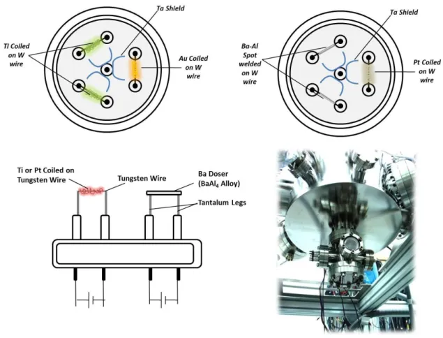
Figure 11.Thin film doser compartment and types/locations of particular dosers.
For the preparation of the Pt, Au, Ti dosers, high-puritywires of these metals with proper diameters (Pt=0.05mm, Au=0.05mm, Ti=0.125mm) were coiled up around a relatively thicker tungsten wire. By passing DC current through tungsten wire with an adjustable voltage/current supply, these metals can be heated up a certain temperature at which evaporation takes place. If the sample is locatedwithin the line of sightof the evaporator, metal particles in the gas phase accumulate on the surface of the sample. Oxide thin films of related metals are then prepared by heating the sample athigh temperatures in an oxidative environment. In order to prevent metal deposition on the critical components of the UHV chamber and other analytic apparatus, tantalum screens were spot-welded around the dosers. These screens also prevent cross-contamination of adjacent metal dosers of different types.
For the productionof the home-made Ba-doser, Bagetter material BaAl4 alloy (ST2/FR wire, SAES Getters) was spot welded on Talegs. These evaporable getters are typically provided in the form of a stable barium-aluminum alloy powder
27
compressed into a metal ring container. The ring-shaped metal container offers the advantage of electrical conductivity. Activation of the getter by resistive heating generatesatomicBa (g) which can readily be deposited on the surface of the substrate. When the getter temperature is raised to approximately 1250 0C,Ba (g) vapor pressure can reachabove 2 mbar. Thus,during Ba deposition, gentle heating with a Ba-doser current of c.a. 10 A is used in order to achieve a controlled dosing condition.
2.2.4 Temperature Controller (Heat Wave Labs Model 101303-46A)
Figure 12.Sample temperature controller unit used in UHV chamber.
Sample temperature was manipulated with an electronic temperature controller (Heat Wave Labs Model 101303-46A). The sample temperature ismeasured with a K-type thermocouple. Type K thermocouple consists of chromel (90% nickel + 10% chromium with 0.05 mm thickness), alumel (95% nickel + 2% manganese + 2% aluminum + 1%silicon with 0.05 mm thickness) alloys. It can be used for the temperature interval of 20 K and 1600 K. Our working temperature interval was between 80 K to 1073 K. After several optimization tests, PID parameters for a linear heating protocol weredetermined. The following parameters were used in the PID algorithms during the linear sample heating ramps: P=70, I=2, D=1. The first parameter, proportional control, depends only on the difference between the set point and the process variable. This difference is referred to as the
28
“error term”. Therefore, proportional control determines the ratio of output response to the error signal.When the value is in the band, the controller adjusts the output based on how close the process value is to the set point. The second parameter, integral, determines the speed of correction. The integral component sums the error term over time. A low integral value causes a fast integration action. The last parameter, derivative, is used to minimize the overshoot in a PI-controlled system. It adjusts the output based on the rate of change in the temperature or process value. If derivative value is too much, then system becomes sluggish. In all of the current experiments, a resistive linear heating rate of 1 K/s was chosen and all the system parameters were optimized according to this linear ramp rate.
2.3 Surface Analytical Techniques
2.3.1 XPS (X-Ray Photoelectron Spectroscopy)
XPS provides information about the elemental composition, the oxidation state of the elements and, in some cases, the dispersion of one phase over another. XPS measures the kinetic energy of photoelectrons emitted from a material due to the photoelectric effect.
Peaks in the XP spectra are described using the quantum numbers of the photoelectrons that are involved in the photoemission process. A particular photoemission peak is labeled via“nlj” formalism [67] in which the principal
quantum number“n” takes the integer values within“1, 2, 3,…,n”, the orbital angular momentum “l” takes integer values within“0, 1, 2, 3,…,n-1”.andQuantum number “l” is represented byhistorical spectroscopic notation in the form “s, p, d, f…”. The peaks in the XP spectra that are derived from orbitals with anangular momentum quantum number greater than 0 are usually split into two different signals. This is the result of the coupling interaction betweenthe orbital angular momentum “l” of anelectron ina given orbital and the magnetic field associated with itsspin quantum number “s” originating from the intrinsic angular momentum of that particular electron. The spin angular momentum quantum number can assume values of±½. These two angular momentavectors can couple either in a favorable (constructive) or
29
in an unfavorable (destructive) fashion yielding a resultant quantum number “j” with a magnitude j = |l±s|For instance, the Pt4f yields two photoemission peaks, 4f7/2 (with
l=3 and j=3+ ½) and 4f5/2 (l=3 and j=3- ½). The degeneracies “g” of the electronic
statesassociated with a particular photoemission peak is given by “g = 2j+1”. Relative degeneracies associated with different spin-orbit splitting peaks (i.e. doublets) dictate the relative intensities of each of the doublets. For example, for a photoemission process involving d-orbital electrons, the relative integrated XPS intensities of the 3/2 and 5/2 peaks are 2:3. Strength of spin orbit coupling defines the binding energy spacing between the doublets. For a given value of both n and l, the separation increases with the atomic number of the atom. For a given atom, it decreases both with increasing n and with increasing l. X-ray notation is also an alternative notation where letters K, L, M etc. are used instead of the principal quantum numbers, while subscript numbers refer to the j values.
Table 4.The relationship between quantum numbers, spectroscopists’ notation and
X-ray notation.[67]
XPS is based on the photoelectric effect, in which an atom absorbs photon energy, hγ, after which a core or valence electron with binding energy Eb is ejected
with kinetic energy, Ek:[68]
Ek = hγ-Eb-W (18)
where Ek is the kinetic energy of the photoelectron, h is the Planck’s constant, γ is
![Table 1.Typical exhaust gas composition of a gasoline powered spark ignition internal combustion engine.[1]](https://thumb-eu.123doks.com/thumbv2/9libnet/5610291.110825/18.892.300.662.711.932/typical-exhaust-composition-gasoline-powered-ignition-internal-combustion.webp)
![Table 2.European Union emission standards for gasoline and diesel powered (within bracket) passenger cars (g km -1 )[4]](https://thumb-eu.123doks.com/thumbv2/9libnet/5610291.110825/20.892.170.736.595.869/table-european-emission-standards-gasoline-powered-bracket-passenger.webp)
![Figure 2.Development of supported model catalysts and comparison of the preparation techniques(adapted from ref.[27])](https://thumb-eu.123doks.com/thumbv2/9libnet/5610291.110825/26.892.225.686.125.779/figure-development-supported-catalysts-comparison-preparation-techniques-adapted.webp)
![Figure 3.Structural parameters and kinetic effects on supported metal catalysts(adapted from ref.[27])](https://thumb-eu.123doks.com/thumbv2/9libnet/5610291.110825/27.892.176.797.709.1004/figure-structural-parameters-kinetic-effects-supported-catalysts-adapted.webp)
![Figure 5.Molecular orbital diagrams of NO and NO 2 [37]](https://thumb-eu.123doks.com/thumbv2/9libnet/5610291.110825/29.892.172.819.320.793/figure-molecular-orbital-diagrams.webp)

![Table 4.The relationship between quantum numbers, spectroscopists’ notation and X-ray notation.[67]](https://thumb-eu.123doks.com/thumbv2/9libnet/5610291.110825/46.892.179.774.619.903/table-relationship-quantum-numbers-spectroscopists-notation-ray-notation.webp)
![Calix[4]amine Langmuir-Blodgett thin film sensing properties against volatile organic compounds](data:image/gif;base64,R0lGODlhAQABAIAAAP///wAAACH5BAEAAAAALAAAAAABAAEAAAICRAEAOw==)