Deploy-DDS: Tool Framework for Supporting Deployment
Architecture of Data Distribution Service based Systems
Turgay Celik
MilSOFT Software Technologies Ankara, Turkey +903122973153
[email protected]
Omer Koksal
ASELSAN Ankara, Turkey +905325404045[email protected]
Bedir Tekinerdogan
Bilkent University, Dept. of ComputerEngineering Ankara, Turkey +903122901187
[email protected]
ABSTRACT
Data Distribution Service (DDS) is the Object Management Group’s (OMG) new standard middleware after Common Object Request Broker Architecture (CORBA), which is becoming increasingly popular. One of the important problems in DDS Based Software Systems is the deployment configuration of DDS modules to the physical resources. In general, this can be done in many different ways whereby each deployment alternative will perform differently. Currently, the deployment configuration is decided after the coding phase and usually performed manually. For large configurations, finding the feasible deployment might require serious rework with costly and time consuming iterations. In this paper, we present the tool Deploy-DDS to support the selection and generation of deployment architectures of DDS based systems. The tool can be used to perform an evaluation during the design phase and generate the selected feasible configuration.
Categories and Subject Descriptors
C.2.4 [Computer-Communication Networks]: Distributed Systems — Distributed applications.
D.2.2 [Software Engineering]: Design Tools and Techniques — Computer aided software engineering (CASE).
D.2.8 [Software Engineering]: Metrics — Performance measures.
D.2.10 [Software Engineering]: Design—Methodologies. D.2.10 [Software Engineering]: Design—Representation. D.2.11 [Software Engineering]: Software Architectures— Domain-specific architectures
G.1.6 [Numerical Analysis]: Optimization — Constrained optimization
General Terms
Measurement, Performance, Design, Reliability, Standardization.
Keywords
Data Distribution Service, Middleware, Research Tool.
1. INTRODUCTION
Distributed systems realize the distributed execution of software systems over multiple resources to meet different requirements and quality factors such as performance, interoperation, multi user support. To reduce the effort for developing distributed systems, common architectures have been introduced including OMG Common Object Request Broker Architecture (CORBA), Java Message Service (JMS), and OMG Data Distribution Service (DDS) [1]. These middleware architectures provide common services such as name and directory services, discovery, data exchange, synchronization, transaction services, etc. DDS has been defined by the OMG to provide a standard data-centric publish-subscribe programming model for distributed systems. DDS has been particularly applied in the development of distributed systems with high performance requirements such as in the defense, finance, automotive, and simulation domains.
Permission to make digital or hard copies of part or all of this work for personal or classroom use is granted without fee provided that copies are not made or distributed for profit or commercial advantage and that copies bear this notice and the full citation on the first page. Copyrights for third-party components of this work must be honored. For all other uses, contact the Owner/Author.
Copyright is held by the owner/author(s). ECSAW , Aug 25-29 2014, Vienna, Austria ACM 978-1-4503-2778-7/14/08.
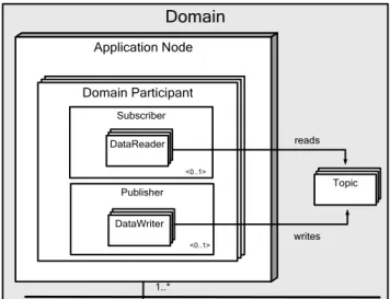
Domain
Application Node 1..* Domain Participant Subscriber Publisher DataReader DataWriter Topic writes reads <0..1> <0..1>Figure 1 Reference Architecture for DDS Based Systems The reference architecture for DDS based systems is shown in Figure 1. A DDS system consisting of several DDS applications is called a Domain. A typical DDS based system is deployed on a number of Application Nodes. Each Application Node includes one or more Domain Participants which are applications that together form the system execution. Each Domain Participant may include one Publisher which represents the objects responsible for data production and updates. A publisher includes one or more Data Writers that publish data of different data types. Domain Participant may also include one Subscriber which is responsible of receiving published data and making it available to the participant. A subscriber includes one or more Data Readers to access published data in a type-safe manner. Interaction between data reader and data writers is established via Topics. A topic defines a unique name, data type and a set of Quality Services to the published/subscribed data [1]. Note that Domain is a logical concept and a Domain Participant may participate to more than one domain at the same time.
One of the important problems in DDS-based systems is the deployment of modules to the corresponding nodes. The reference architecture in Figure 1 can be configured in many different ways based on the module and the physical node properties. For configuring the system the objective is usually to have less network communication and better system performance with respect to resource consumption (e.g. CPU and memory). These performance factors should be taken into account when deploying the software modules on the available physical resources. In general, the selection of the deployment configuration of DDS is performed manually after the development phase. This might require serious rework with costly and time consuming iterations on the design and the related project lifecycle artifacts such as detailed design, implementation, test artifacts, documentation, etc. On its turn this will lead to delays and higher cost in the project. Moreover, if the system is too complex and include many modules and interactions finding a feasible deployment alternative might not be tractable.
In this paper, we offer a tool framework to support the selection and generation of the feasible configurations. Our tool Deploy-DDS can be used to analyze and evaluate the performance of the deployment architecture alternatives even in the design phase before coding started. Deploy-DDS helps software architects to analyze the deployment alternatives and decide the final deployment configuration. The deployment configuration
alternatives are evaluated depending on the available physical resources. The evaluation can be performed during the design phase to minimize the rework effort which is a very important concern in professional software development context.
The remainder of the paper is organized as follows:
In section 2 we present the example case study to illustrate the problem. In section 3 we present the Deploy-DDS tool. Finally, section 4 concludes the paper.
2. EXAMPLE CASE STUDY
To illustrate the problem statement and the approach, we use the case study of the development of a DDS-based city wide Advanced Traffic Management System (ATMS). The ATMS will support optimization of city traffic by analyzing the traffic data collected from the vehicles, traffic cameras, etc. Different from traditional ATMS, the system subject to the case study will support management of autonomous vehicles. The autonomous vehicles will communicate with ATMS to adjust speed, make turns, stop at traffic lights, etc. The ATMS will manage emergency vehicles, traffic lights, ramp meters, variable speed limiters, and hard shoulders in addition to autonomous vehicles. The logical view for the ATMS case study is given in Figure 2. A sample scenario for the case study may contain 300 Autonomous Vehicle Managers, 10 Emergency Vehicle Managers, 20 Traffic Camera Managers, 5 Speed Limiter Managers, 15 Traffic Light Managers, 15 Hard Shoulder Managers, 10 Ramp Meter Managers, and 5 Regional Traffic Manager Managers. Mapping this to a DDS system requires the identification of the different data readers, data writers and the many interactions. Obviously, selecting and generating feasible deployment alternatives for such large scale systems is not trivial and tool support is essential.
Autonomous Vehicle Manager Speed Limiter Manager Traffic Camera Manager Traffic Light Manager * * * * Regional Traffic Manager Network Hard Shoulder Manager * Emergency Vehicle Manager * Ramp Meter Manager * *
Figure 2 Logical view of the case study
3. THE DEPLOY-DDS TOOL
The Deploy-DDS tool provides an integrated environment for modeling DDS based applications, generating and analyzing deployment models. Deploy-DDS tool is built on the Eclipse platform and implemented as a set of plug-ins. The developed plug-ins are built on other Eclipse framework plug-ins including Eclipse Modeling Framework (EMF) [3], Graphical Editing Framework (GEF) [4], and Graphical Modeling Framework (GMF) [5]. EMF is a modeling framework and code generation facility that we use to develop the metamodels. GEF is a framework that is used for generating rich graphical editors and views. GMF is a generative component and runtime infrastructure that we use for developing graphical editors for the developed metamodels. Further, we use Emfatic [6], which provides a text editor and a language for editing EMF models. In addition we use
EuGENia [7] GMF tool that provides mechanisms for abstracting away the complexity of GMF and for easier development of GMF editors. EuGENia tool is a part of Epsilon project [7]. The layered tool architecture of the Deploy-DDS is given in Figure 3.
Physical Resources Design Tool
DDS Types Design Tool DDS Application Design Tool Execution Configuration Design Tool Deployment Model Generation Tool Eclipse Platform EMF GEF GMF E m fa ti c E u G E N ia
Figure 3 Layered Architecture of S-IDE environment
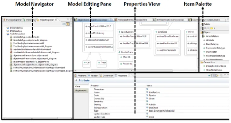
The common perspective of Deploy-DDS tools is given in Error! Reference source not found.. The left pane includes the Model Navigator that shows the available models and their elements. The Model Editing Pane in the middle provides the main drawing area for the simulation design. The Item Palette on the right provides the objects and the connections that are used for creating a design model. The items in this palette can be added to the Editing pane by dragging and dropping. The Properties View at the bottom provides an editing area for the attributes of the design model elements that are selected from the Editing Pane or the Model Navigator.
Figure 4 General Perspective of Deploy-DDS
The remaining part of this section explains each of Deploy-DDS sub-tools showed in Figure 3.
3.1 DDS Types Design Tool:
This tool is used for defining DDS data object model elements that will be used for data exchange among DDS domain participants. Actually, this tool realizes data type section of OMG UML profile for Data Distribution [2]. The tool supports simple datatypes (Integer, Boolean, Char, Enumerations, etc.), Collections (Sequence, Array), Complex Data Types (Union, Topic Structs), and TypeDefs to enable definition of data exchange models.
3.2 DDS Application Design Tool
This tool is used for modeling DDS applications in means of defining Topics, Data Readers, Data Writers, Publish/Subscribe relations, Domain Participants and DDS Domain (Figure 1). This tool also enables association of the topics with applicable data type elements defined with “DDS Types Design Tool”. This tool realizes application definition section of OMG UML profile for Data Distribution [2].
3.3 Physical Resources Design Tool
This tool is used for definition of available physical resources in means of hardware nodes (with their processing power and memory capacity), and the network connections among the nodes. For example, one may decide to adopt 6 nodes on which the DDS Domain Participants will be deployed. Further it could be decided that each node contains two processing units at the frequency of 3.2 MHz and memory capacity of 36840 MB. All nodes in the design are not supposed to be identical; they could have different memory capacity and processing powers.
3.4 Execution Configuration Design Tool
This tool is used for definition of the run-time properties of the domain participants, domain and publish/subscribe relations defined with “DDS Application Design Tool”. In this context, the number of each domain participants in the domain, the update rate of domain participants for each publication, and the execution cost of each domain participant instance on each target node defined in Physical Resources Design Tool. This tool provides some shortcuts to enable definition of large scenarios. For example, user can add a domain participant to the execution configuration and define total instance count (e.g. 250) instead of adding same domain participant 250 times one by one.
3.5 Deployment Model Generation Tool
After both the static and run-time properties of the DDS application, the domain participants and the physical resources are defined within previous tools; this tool enables automatic generation and analysis of deployment model alternatives. Deployment model generation process can be summarized as follows:
1. Derive the necessary parameter values (tasks, data exchange relations of tasks, available resources) from the design for the algorithms that define feasible deployment alternatives.
2. Take the outputs of the previous parameter extraction step as input parameters and execute the task allocation algorithms to compute feasible deployment alternatives. If a feasible deployment is found, this activity yields a table that represents the mapping of tasks (domain participant instances) to processors (nodes in physical resources design). The designer can select different algorithms to generate deployment alternatives. (It is also possible to extend
Deploy-DDS tool by adding new algorithm
implementations as Eclipse plugins. Deploy-DDS tool searches and automatically detects available
algorithm implementations via OSGI services provided by Eclipse Equinox framework [9]. Deploy DDS tool provides a genetic algorithm implementation [10] out of the box.)
3. If no feasible solution was found in the previous step, detailed feedback is presented to the designer to optimize the design model. The designer will first try to update the execution configuration with “Execution Configuration Design Tool”. If a feasible deployment can still not be found, then the designer can decide to return to the beginning of the process to refine the DDS types and/or DDS application design according to tool feedback. For example, the designer may use calculated data exchange amounts among domain participants to detect anomalies/potential optimization points and update data update rates defined in “Execution Configuration Design Tool”.
4. If at least one feasible deployment alternative is found, the task-processor mapping tables that are the output of the Step 2 will be used to generate one or more deployment models.
5. The designer evaluates the generated deployment model by comparing it with other alternative deployment models. The alternative deployment models to compare may be the other models generated by the selected algorithm if the algorithm in Step#4 generates more than one deployment models. The designer may also compare the generated deployment models with models generated by alternative algorithms or even manually generated deployment models with expert judgment. The Deploy-DDS tool provides automatic analysis and comparison capabilities to enable evaluation of alternative deployment models. The generated deployment models will be improved until they are considered to meet the expected communication and execution costs. If a satisfying deployment model cannot be found, the designer uses diagnostic feedback report generated by the Deploy-DDS tool to improve the design.
4. CONCLUSION
One of the important problems in DDS based systems is the allocation of the different modules to the available nodes. Usually, the deployment of the modules to the nodes can be done in many different ways. We have developed a tool framework, Deploy-DDS that provides an integrated development environment for deriving feasible deployment alternatives. The tool framework consists of several tools for modeling, generating and analyzing of the deployment alternatives.
5. REFERENCES
[1] OMG, Jan 2007, Data Distribution Service for Real Time Systems (DDS), http://www.omg.org/spec/DDS/
[2] OMG, May 2010, UML Profile for Data Distribution Specification, http://www.omg.org/spec/UML4DDS/ [3] Budinsky, F., Steinberg, D., Merks, E., Ellersick, R., and
Timothy J. Grose. 2003. Eclipse Modeling Framework. Addison-Wesley Professional.
[4] Moore, W., Dean, D., Gerber, A., Wagenknecht, G., Vanderheyden, P., 2004. Eclipse Development using the Graphical Editing Framework and the Eclipse Modeling Framework. IBM RedBooks.
[5] Voelter, M., Kolb, B., Efftinge, S., Haase, A. 2006. From Front End To Code – MDSD in Practice,
http://www.eclipse.org/articles/Article-FromFrontendToCode-MDSDInPractice/article.html.
[6] Daly, C. 2004. Emfatic Language Reference. http://www.eclipse.org/gmt/epsilon/doc/articles/emfatic/. [7] Kolovos, Dimitrios S., Rose, Louis M., Abid, S., Paige,
Richard F., Polack, Fiona A. C., and Botterweck, Goetz. 2010. Taming EMF and GMF Using Model Transformation. In Model Driven Engineering Languages and Systems, Lecture Notes in Computer Science, Springer Berlin / Heidelberg, vol. 6394, ch.15, 211-225.
[8] Kolovos, Dimitrios S, Paige, Richard F. and Polack, Fiona A. C. 2006. Eclipse Development Tools for Epsilon. In Eclipse Summit Europe, Eclipse Modeling Symposium.
[9] McAffer, J., Vanderlei, P., and Archer, S. 2010. Osgi and Equinox: Creating Highly Modular Java Systems (1st ed.). Addison-Wesley Professional.
[10] Mehrabi, A., Mehrabi, S. and Mehrabi, A.D. 2009. An Adaptive Genetic Algorithm for Multiprocessor Task Assignment Problem with Limited Memory. In Proceedings of the World Congress on Engineering and Computer Science 2009 Vol II
Appendix – Presentation Outline
The Deploy-DDS tool is a complete research prototype tool. With the tool we have implemented all of the five tools of the framework which are:
(1) DDS Types Design Tool (2) DDS Application Design Tool (3) Physical Resources Design Tool (4) Execution Configuration Design Tool (5) Deployment Model Generation Tool
The video of the Deploy-DDS tool can be found on the following of the YouTube video server:
http://youtu.be/l_pXo_NrQ30
For more information about the tool please refer to https://code.google.com/p/dds-modeling-tools/wiki/Introduction
The presentation will consist of the following steps:
- Short discussion on Data Distribution Service and the problem statement
- Short discussion on Deployment Model Generation Approach
The deployment model generation approach which will be used as our case study as such we need to explain this beforehand.
- Explanation of the metamodel based tool architecture of Deploy-DDS
This will include an outline of the basic tool framework. Short explanation about the supporting tools will be given.
- Modeling DDS Based Applications and Generating Deployment models in Deploy-DDS
After the overall motivation and the structure of the tool are explained, we will show realization of deployment model generation approach in Deploy-DDS tool.
- Summary and possible extensions of the tool