ORIGINAL ARTICLE
On properties at interfaces of friction welded
near-nanostructured Al 5083 alloys
Mumin Sahin&N. Balasubramanian&Cenk Misirli&
H. Erol Akata&Yilmaz Can&Kaan Ozel
Received: 2 March 2011 / Accepted: 14 November 2011 # Springer-Verlag London Limited 2011
Abstract Equal-channel angular pressing is a material processing method that allows very high strains to be imposed, which leads to extreme work hardening and micro-structural refinement, with minimal change of external sample dimensions. It offers possibilities of good mechanical properties, such as high strength and ductility, while allowing flexibility of choice of alloy composition for better corrosion behavior, lower materials costs, and so on. This study characterizes for the first time the microstructure and properties of aluminum friction welded after severe plastic deformation via the equal-channel angular pressing method. In this study, 5,083 aluminum alloys, which were exposed to severe plastic deformation using square cross-sectional equal-channel angular pressing die, were joined with friction welding method. It was found that tensile and fatigue strengths of severe plastic deformed and welded specimens were higher than those of the purchased specimens. Hardness values were also consistent with the strength results. However, the refining of grain size as shown from microstructures results in a significant increase in hardness and mechanical properties.
Keywords ECAP . Friction welding . Aluminum . Mechanical properties . Microstructure
1 Introduction
Nano and near-nano crystalline metals and alloys are of great interest because of their unique combination of mechanical and physical properties that are potentially superior to those of their coarse-grained counterparts. In order to provide a better understanding of the deformation behavior of nano-structured and near-nanostructured mate-rials, it is essential to test these materials in bulk form. Equal-channel angular pressing (ECAP) is one approach that is currently employed to generate ultra-fine-grained or near-nano grain-sized bulk materials with sufficient thermal stability. The average grain sizes obtainable by ECAP processes are reported to be 200–1,000 nm [1].
In metallic materials, there are two ways of obtaining ultra-fine grain to develop mechanical properties. These are
severe plastic deformation at temperatures below 0.3 Tm
(Tmis the melting point) and powder metallurgy methods. The severe plastic deformation is known as the plastic deformation of a metallic material, which is exposed to the high-degree plastic strain, at temperatures below 0.3 Tm. Severe plastic deformation takes place during the division of coarse-grained microstructures to a regular form of cell blocks and dislocation cells. While the strain of the material increases, the microstructural dimension decreases. The traditional methods for material manufacturing do not provide a possibility to deform the material without damage at high strains.
A number of research studies have been recently attempted to obtain the nano-structure in metallic materials by imposing severe plastic deformation (SPD). Among
M. Sahin (*)
:
C. Misirli:
Y. Can:
K. OzelMechanical Engineering Department, Trakya University, 22180 Edirne, Turkey e-mail: [email protected] N. Balasubramanian (*) R V College of Engineering, Bangalore, India e-mail: [email protected] H. E. Akata
Mechanical Engineering Department, Istanbul Aydin University, Istanbul, Turkey
SPD techniques, particularly ECAP has been widely used to produce the bulk nano-crystalline materials without
residual porosity and volume change [2–4], and the
advantages of ultra-fine grains such as higher strength, toughness, and enhanced superplasticity are well known. Metallic structures require joining of parts by some methods such as welding. It is important that the fine grains obtained by ECAP do not become coarse or altered drastically during welding. It is therefore necessary to choose the proper method of welding, and a low-temperature solid-state process such as friction welding (FW) becomes important in this context.
2 Severe plastic deformation and equal-channel angular pressing
The most characteristic property of ECAP is to maintain constant the cross-sectional area of the material after the process. Therefore, plastic deformation to higher strains is possible without the cross-section change. Hence, a specimen can be exposed to severe deformation with more than one pass for increasing the plastic strain. In this process, knowledge of the plastic deformation behavior of the work-piece during the process is very important for the determination of the optimum process conditions such as die design, speed, temperature, friction, and preform design.
There are two equal-sized channels, which cut each other on 90° angles, in the ECAP method as shown in Fig.1. The raw material is pressed by a punch from one side of the channel, and then it is extracted from the other side without changing in size. At this time, the material exposes to shear deformation. The process can be repeated more than once to increase the amount of strain resulting from plastic deformation.
Equal cross-section lateral extrusion is a special form of ECAP. In this method, there are two channels, which cut
each other with more than 90°. The form of that channel is
like as S letter and θ angle is same at each tip of the
channel, and is named as S-type Equal Cross-Section Lateral Extrusion. Also in this method, the material is pressed from one side of the channel by means of a punch and it is taken out from the other side with deformation but without any changing in sizes. The process can be repeated more than once to increase the total strain [5–12].
3 Friction welding method
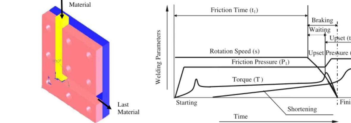
In this process, heat is generated by conversion of mechanical energy into thermal energy at the interfaces of the components during rotation under pressure. Some of the advantages of friction welding are high material savings, low production time, and possibility of welding of parts which consist of different metals or alloys. Friction welding can also be used in order to join the components that have circular or noncircular cross-sections. Friction time, friction pressure, upset time, upset pressure, and rotation speed are the most important parameters of friction welding.
Generally, friction welding is divided into two methods: continuous drive friction welding and inertia friction welding [13–21].
3.1 Continuous drive friction welding
In continuous drive method, which is used in the present study, one of the components is rotated at constant speed (s), while the other is pushed toward the rotated part by a sliding action under a predetermined pressure—friction pressure (P1). Friction pressure (P1) is applied for a certain friction time (t1). Then, the drive is released and the rotary component is quickly stopped while the axial pressure is being increased to a higher predetermined upsetting pressure (P2) for a predetermined time (t2). The parameters of the welding method are shown in Fig. 2[15–21]. Test
Material
Last Material
Fig. 1 Schematic of equal channel angular pressing method
Starting Friction Pressure (P1) Rotation Speed (s) Friction Time (t1) Time Upset (t2) Torque (T ) Braking Upset Pressure (P2) Shortening Finishing Waiting Welding Parameters
The research on friction welding started in 1970s and the field has grown rapidly. Kinley has discussed the principles
of friction welding [13]. Murti et al. [14] found the
parameters of importance in friction welding by the help of statistical analysis. Sahin et al. studied friction welding of high speed, medium carbon, and austenitic stainless steels experimentally [15–19] and by computer simulation
[20]. Since ECAP of Al 5083, a commercially important
alloy, and its properties have been well studied [3–5,8,12], it has been chosen in this work to investigate the effect of FW. The tensile, fatigue, hardness, microstructural proper-ties, and X-ray diffraction patterns of ECAP and FW Al 5083 are presented and discussed.
4 Experimental study
Aluminum alloy as test material 5083 and square cross-sectional equal channel angular pressing die for severe
plastic deformation were used in the study. This alloy was chosen since information on ECAP and FW of this material
is available in the literature [1, 21]. The chemical
composition of AA5083 material is given in Table1. At first, 5083 alloys, as received, were joined by friction welding method. The optimum parameters for friction time, upset time, friction pressure, and upset pressure, which are necessary for welding, were obtained. Later, rolled 5083 aluminum materials as received were prepared as square cross-section (length 70 mm and width 12 mm), and then one-pass severe plastic deformation was applied to the specimen by equal-channel angular pressing die. The obtained parts in square form were prepared as cylindrical form by machining, and then the parts were joined by continuous drive friction welding equipment that was designed and produced in laboratory conditions discussed earlier. Later, various tests were done on the parts. 4.1 Die for equal-channel angular pressing
In this study, square die was chosen because of ease of machining, and then the purchased aluminum alloys were deformed for one-pass. A 150-metric-ton press was used for deformation. A photograph of the die used for the experiments is given in Fig.3.
4.2 Friction welding experiment
Firstly, received 5083 aluminum work-pieces were joined by friction welding without any plastic deformation to obtain the optimum welding parameters. Afterwards, a part
Table 1 Chemical composition of AA5083-H111 aluminum alloy [21]
Material % Si % Fe % Cu % Mn % Mg % Cr % Ni % Zn % Ti Others Tensile strength of received material (MPa)
% each % total
AA 0.40 0.40 0.10 0.30 4.0 0.05 – 0.25 0.15 0.05 0.15 305
5083 – – –
1.0 4.9 0.25
x 1
Fig. 3 Photograph of the die used in the experiment
s (rpm)
P1(MPa),
t1(sec)
d1 (mm) d2 (mm)
Chuck
of received work-pieces was exposed to one-pass severe plastic deformation. ECAP die needed for deformation was prepared. ECAP is a plane strain process. In this respect, the cross-section of the deformed material is not important. With this aim, a square die was machined because of easy machining, and purchased aluminum alloys were deformed. Later, the obtained parts were joined by friction welding method using optimum parameters. In this study, a continuous drive friction welding setup is used under laboratory conditions and a schematic of the parts is shown in Fig.4.
Parameter optimization was carried out using a factorial design of experiments. The two factors chosen were friction time and friction pressure. The other parameters such as upset time, upset pressure, and rotational speed were maintained constant. The experimental results for factors are given in Table2.
Then, parameters having the least error using the method of least squares with statistical analysis in the welding experi-ments were taken as the optimum welding parameters in pilot experiments. The optimum parameters obtained by using the above-mentioned procedure are friction time=3 s, friction pressure=35 MPa, upset time=15 s, and upset pressure=
90 MPa [21]. However, the motor power of the setup is
4 kW, and the rotational speed of the motor is 1,410 rpm. Later, tensile and fatigue samples were machined from both unwelded and welded aluminum parts as seen in Fig.5. The optimum welding conditions are given in Table3.
5 Experimental results
Two sets of welding experiments keeping the upset time (15 s) and upset pressure (90 MPa) constant were done in order to
obtain proper friction time and friction pressure. In the first set, friction times were changed while friction pressures (35 MPa) were kept constant. In the second set, friction pressures were changed while friction time (3 s) was kept constant.
5.1 The tensile tests
Tensile tests were conducted using an Instron 8501 machine. The specimen was clamped to the grips at both Table 2 Experimental results for factors
Trial no. Friction pressure
(MPa) (x1) Friction time (s) (x2) Tensile strength (MPa) 1 35 1 95.5 2 40 3 300 3 35 3 305 4 40 5 290 5 45 3 95 10 25 10 55 5 Ø 10
Fig. 5 Geometry of tensile and fatigue samples, dimensions in mm
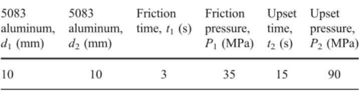
Table 3 Parameters used in the friction welding experiments 5083 aluminum, d1(mm) 5083 aluminum, d2(mm) Friction time, t1(s) Friction pressure, P1(MPa) Upset time, t2(s) Upset pressure, P2(MPa) 10 10 3 35 15 90
ends. The upper grip was fixed, but the vertical position could be adjusted to accommodate specimens of different sizes. The lower grip was driven by a hydraulic actuator. Vertical movement of the lower grip generated the desired loading on the specimen.
In pilot experiments, received aluminum alloy specimen was prepared in cylindrical form by machining and was joined, and then the tensile strengths were investigated. The variation of calculated tensile strengths according to the friction time and friction pressure is given in Figs.6and7. Those of the obtained parts with welded joints were machined and the tensile strengths of these parts were also measured, and averages were indicated as“material tensile strength” at diagrams. The tensile strengths of the joints were estimated as dividing the ultimate loads by area of 10 mm in diameter. Afterwards, aluminum alloys were subjected to one-pass ECAP and prepared in cylindrical form. Then, these were joined by friction welding method, and tensile strengths were investigated. The variation of calculated tensile strengths according to the friction time and friction pressure is also given in Figs.6 and7. Fig. 7 The effect of friction pressure on tensile strength
f= m ± a
f : Fluctuating Stress (MPa) m : Mean Stress (MPa) a : Stress Amplitude (MPa)
a m
f
- Fluctuating Stress
Time Fig. 8 Fatigue test results of
aluminum
x 5
5.2 Fatigue tests
The fatigue tests were performed in an Instron 8501 machine. During the tests, the load application frequency was 20 Hz. Some of the machined and welded parts were exposed to the fatigue tests under axially tension as linear. The geometry of parts tested is given in Fig.5. The fatigue test machine stopped automatically as soon as specimen failure occurred.
In fatigue tests, received aluminum, welded as received, and severe plastic deformed joints were analyzed in the same constant tensile loads and stress amplitudes. In all experi-ments, fatigue tests were conducted as superimposing some fluctuating tensile loads on a constant tensile load (Fig.8).
5.3 Microstructural examination
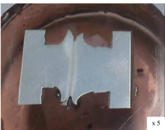
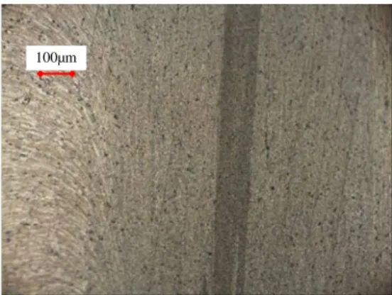
For aluminum joints, a macrostructure photo is shown in Fig.9. Then, microstructure photos in the base metals and welding zone of the joints after etching in Keller’s reagent
are shown in Figs. 10, 11, 12, and 13. Moreover, XRD
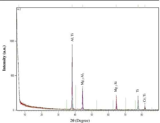
analysis was performed in order to investigate the phases that occur at the interface of the joints. XRD analysis
results on welded aluminum and SPD welded aluminum are given in Figs.14and15, respectively.
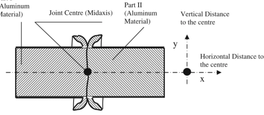
5.4 Hardness profile
The strength of the joints is related with the hardness profile within HAZ. Hardness profile was obtained by microhard-ness testing at different locations (Fig.16). Hardness profile on horizontal distance for welded aluminum material and
welded one-pass ECAP aluminum are given in Fig.17.
6 Discussion
As can be seen in Figs. 6 and 7, the strengths of joints
increase with friction time and friction pressure. In addition, the values obtained as highest strengths were accepted as optimum value for friction pressure and friction time (t1=
3 s and P1=35 MPa). However, while the received 5083
aluminum alloys’ tensile strengths were approximately 305 MPa, one-pass severe plastic deformed 5083 aluminum parts’ tensile strengths were found as 420 MPa in the investigations. The tensile strengths of aluminum because 100µm
Fig. 10 Microphotograph of aluminum material, base metal
100µm
Fig. 11 Microphotograph of one-pass severe plastic deformed aluminum, base metal
100µm
Fig. 12 Microphotograph of aluminum material, welding zone
100µm
Fig. 13 Microphotograph of one-pass severe plastic deformed aluminum, welding zone
of one-pass severe plastic deformation material increase with friction time and friction pressure. It shows that the values of severe plastic deformed material increase due to strain hardening. Nevertheless, while the tensile strength of received and friction welded specimens equals each other, the tensile strength of ECAP-processed aluminum with
ultra-fine-grained effect is about 1.4 times larger than the received one [8,9,21].
Fatigue tests were conducted as superimposing some fluctuating tensile loads on a constant tensile load. Constant tensile load was determined to produce 175-MPa tensile stresses. Fluctuating tensile stress amplitudes were changed
Intensity (a.u.) 2θ (Degree) Al; Ti Mg 2 Al 3 Mg 2 Si Ti Cr; Ti
Fig. 14 The XRD diffraction patterns in weld zone for welded aluminum 2θ (Degree) Intensity (a.u.) Al Al; Cr 2 Ti Fe; Cr 2 Ti Mg 2 Al 3 Mg 2 Si
Fig. 15 The XRD diffraction patterns in weld zone for SPD welded aluminum
between 75 and 125 MPa, and numbers of cycles to fracture were recorded. As can be seen in Fig.8, the fatigue life of received specimens is longer than both ECAP-processed and welded ones, and the difference in fatigue life increases with an increase in stress amplitude. Moreover, the fatigue strength of received aluminum is greater than both welded and deformed-friction welded one. It was considered that the heat generated in friction welding process decreased the fatigue strength of the specimens.
However, it can be seen in Fig.10that the burr in joints is equal on both sides of the aluminum material. Generally, in alloys of the 5xxx series, particles of Mg2Al3, Mg2Si, and intermetallic phases containing chromium and manganese are sometimes present. Figure10shows the particles of primary MnAl6(gray, outlined). Small, dark areas may be particles of insoluble phases—such as phases that contain magnesium (for example, Mg2Si) or that contain manganese [22].
It is obvious that the particle orientation of insoluble phases is due to severe plastic deformation. In case of one-pass plastic deformation as shown in Fig.11, the size of the grain is about
200 nm in width [9, 10]. Particles were dissolved more
compared to the previous stage (Fig. 10) due to the heating effect of FW. Particles were accumulated due to the heat effect compared to that of the previous stage (Fig.11).
During welding, plastic deformation and recrystallization of weld metal by upset pressure and friction heat usually occurred. These may lead to a change of phase constituents in the welding zone. Moreover, some intermetallics might be also formed in the weld zone. Those intermetallics can decrease the mechanical properties of friction welded joints. Therefore, an XRD analysis of phase constituents in the weld zone is quite important. In this experiment, the weld zone of the joint was analyzed. The XRD results of the weld zone in the joints are given in Figs.14and15.
According to Fig.14, the X-ray diffraction results in welded aluminum indicated that there are AlFe, AlFe3, Mg2Al3, Mg2Si, AlCrFe2, AlTi3, and Al13Fe4intermetallics formed in the welding zone. However, intermetallic phases such as AlCr, AlTi, AlFe3, Mg2Al3, Mg2Si, and AlFe in SPD welded aluminum were obtained in the welding zone (Fig.15).
As can be seen in Fig. 17, while the received 5083
aluminum alloys’ hardness was approximately 78 HV, one-pass severe plastic deformed 5083 aluminum parts’ hard-ness was increased. However, maximum hardhard-ness values of joint were obtained away from the weld interface. Severe plastic deformation increases both material strength and material hardness. Therefore, hardness of one-pass severe
plastic deformed material increases as shown in Fig. 17,
and although the friction experiment concludes in a short time, the hardness of the joints decreases due to annealing effect after cold deformation at the welding zone. Further experiments are in progress to optimize the revolution speed to achieve higher hardness in the welding zone.
7 Conclusions
Mechanical and metallurgical properties of one-pass severe plastic deformed and friction welded aluminum were investigated in this study. Friction welded parts were
Joint Centre (Midaxis) Vertical Distance
to the centre
x
y
Part I (Aluminum Material) Part II (Aluminum Material) Horizontal Distance to the centreFig. 16 Hardness test profile
subjected to tensile and fatigue and hardness tests and the phase constituents of the weld zone were determined by X-ray diffraction. The microstructural features of the specimens were investigated by metallographically. The following conclusions were reached:
– It is seen that the tensile strength of the joint increases as friction time and friction pressure increase. However, tensile strength of joints reaches a maximum and then decreases due to heating effects.
– The fatigue strength and fatigue life of received aluminum is greater than both welded and deformed friction welded ones.
– The refining of grain size by ECAP results in a significant increase in hardness and mechanical properties.
– The X-ray diffraction analysis indicates the presence of intermetallic compounds which would influence the mechanical properties of the joint when joining aluminum materials.
– Increases in the tensile strength and hardness are maximal at the first pass of ECAP. However, maximum hardness for one-pass severe plastic deformed 5083 aluminum parts was obtained away from the weld interface because of recrystallization effect after work hardening.
– It is established that the tensile strength of the ECAP material remains nearly the same after FW. Studies to optimize the rotation speed in FW to improve the properties of the interface are currently in progress.
Acknowledgements The authors would like to thank Trakya
University, Edirne, Turkey, and Hema Industry, Çerkezköy, Turkey, for their support of this study.
References
1. Kawasaki M, Balasubramanian N, Langdon TL (2011) Flow mechanisms in ultrafine-grained metals with an emphasis on
superplasticity. Mater Sci Eng A 528:6624–6629
2. Segal VM, Reznikov VI, Drobyshevskiy AE, Kopylov VI (1981) Russ Metall 1:99
3. Shin DH, Kim YS, Lavernia EJ (2001) Acta Mater 49:2387
4. Chang S-Y, Ahn B-D, Hong S-K, Kamado S, Kojima Y, Shin DH (2005) Tensile deformation characteristics of a nano-structured
5083 Al alloy. J Alloys Compd 386:197–201
5. Ozel K (2005) The effect of severe plastic deformation methods to the mechanical properties of aluminum alloys. M.Sc. thesis. Graduate School of Natural and Applied Sciences of Trakya University, Edirne, Turkey
6. Liu Z, Wang Z (1999) Finite-element analysis of the load of equal-cross-section lateral extrusion. J Mater Process Technol
94:193–196
7. Lee DN (2000) An upper-bound solution of channel angular
deformation. Scr Mater 43:115–118
8. Horita Z, Fujinami T, Nemoto M, Langdon TG (2001) Improvement of mechanical properties for Al alloys using equal-channel angular
pressing. J Mater Process Technol 117:288–292
9. Valiev RZ, Alexandrov IV, Zhu YT, Lowe TC (2002) Paradox of strength and ductility in metals processed by severe plastic
deformation. J Mater Res 17(1):5–8
10. Ivanisenko Y, Wunderlich RK, Valiev RZ, Fecht H-J (2003) Annealing behaviour of nanostructured carbon steel produced by
severe plastic deformation. Scr Mater 47:947–952
11. Alkorta J, Sevillano JG (2003) A comparison of FEM and upper-bound type analysis of equal-channel angular pressing (ECAP). J Mater Process Technol 141:313–318
12. Balasubramanian N, Langdon TG (2005) An analysis of superplastic flow after processing by ECAP. Mater Sci Eng
A 410–1:476–479
13. Kinley W (1979) Inertia welding: simple in principle and
application. Weld and Met Fab October. 585–9
14. Murti KGK, Sundaresan S (1983) Parameter optimization in
friction welding dissimilar materials. Met Constr 15(6):331–335
15. Akata HE, Sahin M (2003) An investigation on the effect of dimensional differences in friction welding of AISI 1040 Specimens.
Ind Lubr Tribol 55(5):223–232
16. Sahin M, Akata HE (2003) Joining with friction welding of
plastically deformed steel. J Mater Process Technol 142:239–246
17. Sahin M, Akata HE (2004) AN experimental study on friction welding of medium carbon and austenitic stainless steel components.
Ind Lubr Tribol 56:122–129
18. Sahin M (2005) Joining with friction welding of high-speed steel and medium-carbon steel. J Mater Process Technol 168:202–210 19. Sahin M (2005) An investigation into joining of austenitic-stainless steels (AISI 304) with friction welding. Assem Autom 25(2):140–145
20. Sahin M (2004) Simulation of friction welding using a developed
computer program. J Mater Process Technol 153–4:1011–1018
21. Sahin M, Akata HE, Özel K (2008) An experimental study on joining of severe plastic deformed aluminium materials with
friction welding method. Mater Des 29(1):265–274
22. ASM (1985) ASM metals handbook, 8th edn. ASM, Metals
![Table 1 Chemical composition of AA5083-H111 aluminum alloy [ 21 ]](https://thumb-eu.123doks.com/thumbv2/9libnet/4190835.64925/3.892.93.817.106.237/table-chemical-composition-aa-h-aluminum-alloy.webp)