DESIGN, CONTROL, MODELING, AND
LOCOMOTION ANALYSIS OF A
MULTI-LEGGED MODULAR MINIATURE
ROBOT WITH SOFT BACKBONES
a thesis submitted to
the graduate school of engineering and science
of bilkent university
in partial fulfillment of the requirements for
the degree of
master of science
in
mechanical engineering
By
Nima Mahkam
July 2020
DESIGN, CONTROL, MODELING, AND LOCOMOTION ANAL-YSIS OF A MULTI-LEGGED MODULAR MINIATURE ROBOT WITH SOFT BACKBONES
By Nima Mahkam July 2020
We certify that we have read this thesis and that in our opinion it is fully adequate, in scope and in quality, as a thesis for the degree of Master of Science.
Onur ¨Ozcan(Advisor)
Yildiray Yildiz
Evren Samur
Approved for the Graduate School of Engineering and Science:
Ezhan Kara¸san
ABSTRACT
DESIGN, CONTROL, MODELING, AND
LOCOMOTION ANALYSIS OF A MULTI-LEGGED
MODULAR MINIATURE ROBOT WITH SOFT
BACKBONES
Nima Mahkam
M.S. in Mechanical Engineering Advisor: Onur ¨Ozcan
July 2020
Soft Modular Legged roBot (SMoLBot) is a legged, foldable, modular, miniature robot with soft backbones. SMoLBot’s body and locomotion mechanisms are folded out of acetate sheets and its compliant connection mechanisms are molded from Polydimethylsiloxane (PDMS). High maneuverability and smooth walking pattern can be achieved in miniature robots if high stiffness kinematic parts are connected with compliant components, providing the robot structural compliance and better adaptability to different surfaces. SMoLBot is exploiting features from origami-inspired robots and soft robots, such as low weight and low cost foldable rigid structures and adaptable soft connection mechanisms made of PDMS. Every single module in SMoLBot is actuated and controlled by two separate DC motors, that enable gait modification and a higher degree of freedom on controlling the motion and body undulation of the robot in turning and rough terrain locomotion. Each module has 44.5 mm width, 16.75 mm length, and 15 mm height, which is approximately the same size as two DC motors and a Li-Po battery.
The dynamic formulation of SMoLBot is obtained using Newton-Euler formula-tion and it depends on the physical parameters of the contact and closed-chain kinematic analysis of the feet. The dynamic model framework is proposed by determining the dynamic locomotion parameters of each module as an individ-ual system, as well as, considering the dynamics of the whole robot; i.e. the robot is modeled as one system and modules are considered to be set of flexible links connected to each other, within this system. Kinematic constraints among these modules are obtained by considering the types of backbones integrated in the robot. Various types of backbones are used within the experiments that are
iv
classified into two groups: rigid, and compliant backbones. Experimental re-sults of SMoLBot running/walking with different symmetrical and asymmetrical gates validate the dynamic model presented in this thesis. Additional to the dy-namic model, the effect of the backbone stiffness on the locomotion of the legged miniature modular robots with multiple numbers of modules is studied. Analyses comparing the velocity of SMoLBot with different numbers of modules and dif-ferent types of backbones are presented using the proposed dynamic model. The results indicate that there is an optimum torsional stiffness of the backbone for a legged miniature modular robot that maximizes the robot’s translational velocity. Additionally, we can show that, for a given backbone stiffness or a specific range of compliance between the modules, there is an optimum number of feet for the miniature robots.
Furthermore, in this thesis, a locomotion study that investigates the motion pat-terns of the running/walking multi-legged modular miniature robots with soft module connections, is conducted. The locomotion study is done using the pre-sented dynamic model and results are verified using SMoLBot. The optimum feet sequence and the optimum stride length of a multi-legged robot are derived using the locomotion analyses, and the dynamic and kinematic formulations. The opti-mum gait analysis of the multi-legged SMoLBots represents different but unique feet contact sequence patterns for each robot with a different module number and diverse ranges of compliance between the modules. Furthermore, analysis considering the effect of various feet failure cases on the locomotion of a multi-legged robot with soft/rigid backbones, is conducted. This study investigates the locomotion behavior of a legged miniature robot with different combinations of the non-functioning feet. Additionally, a case-sensitivity study of an n-legged SMoLBot’s locomotion on its individual modules during the operation, is also conducted. This study investigates the modular robot’s locomotion with multi-ple different failure cases where each particular case only considers the effect of an individual module failure on the overall motion of the robot, while the gate is not altered.
Keywords: miniature robotics, foldable robotics, dynamic simulation, multi-legged modular robots, gait analysis, stiffness analysis, soft backbones.
¨
OZET
YUMUSAK OMURGALI C
¸ OK BACAKLI MOD ¨
ULER
M˙INYAT ¨
UR ROBOTUN TASARIMI, KONTROL ¨
U,
MODELLENMES˙I VE LOKOMOSYON ANAL˙IZ˙I
Nima Mahkam
Makine M¨uhendisli˘gi, Y¨uksek Lisans Tez Danı¸smanı: Onur ¨Ozcan
Temmuz 2020
Yumu¸sak Mod¨uler Bacaklı Robot (Soft Modular Legged roBot - SMoLBot), minyat¨ur, mod¨uler, katlanabilir ve yumu¸sak-sert karı¸sık olan ve esnek omurgaya sahip bacaklı bir robottur. SMoLBot’un g¨ovdesi ve hareket mekanizmaları ase-tat ka˘gıtlarından katlanır ve esnek ba˘glantı mekanizmaları Polidimetilsiloksandan (PDMS) kalıplanarak ¨uretilir. Y¨uksek direngenli˘ge sahip kinematik par¸calar es-nek bile¸senlerle ba˘glandı˘gında, robotun yapısal esnekli˘gi artar ve farklı y¨uzeylere daha iyi uyum sa˘glar dolayısıyla minyat¨ur robotların manevra kabiliyeti artar ve daha d¨uzg¨un bir y¨ur¨ume e¸sekli elde edilebilir. SMoLBot, d¨u¸s¨uk a˘gırlıklı ve d¨u¸s¨uk maliyetli katlanabilir sert yapılar ve PDMS’lerden yapılmı¸s esnek ba˘glantı mekanizmaları gibi hem origamiden ilham alan robotların hem de yumu¸sak robot-ların ¨ozelliklerini kullanıyor. SMoLBot’taki her bir mod¨ul, iki ayrı DC motor ile hareket ettirilir ve kontrol edilir; bu durum, y¨ur¨ume ¸seklinin de˘gi¸stirilmesini ve robotun d¨on¨u¸s¨u ve engebeli arazide hareketi sırasında robotun hareketini ve g¨ovde salınımını kontrol etme konusunda daha y¨uksek bir serbestlik derecesi sa˘glar. Her mod¨ul 44.5 mm geni¸sli˘ge, 16.75 mm uzunlu˘ga ve 15mm y¨uksekli˘ge yani yakla¸sık olarak iki DC motor ve bir Li-Po pil ile aynı boyuta sahiptir.
SMoLBot’un dinamik modellemesi Newton-Euler form¨ulleri kullanılarak elde edilir ve ayakların temas parametrelerine ve kinematik analizinin fiziksel parame-trelerine ba˘glıdır. Dinamik modelin altyapısı, t¨um robotun dinamik yapısı g¨oz ¨
on¨unde bulundurulurken aynı zamanda da her bir mod¨ul¨un ayrı birer sistem olarak de˘gerlendirilmesiyle, yani robotun t¨um¨uyle bir sistem olup mod¨ullerin ise bu sistemin i¸cinde birbirine ba˘glı esnek birer ba˘glantılardan ibaret oldu˘gu
vi
d¨u¸s¨un¨ulerek olu¸sturtulmu¸stur. Mod¨ullerin kinematik kısıtlamaları robotta kul-lanılan omurganın tipine g¨ore bulunmu¸stur. Deneylerde kullanılan omurgalar sert ve esnek omurgalar olmak ¨uzere iki gruba ayrılır. Farklı simetrik ve asimetrik y¨ur¨ume ¸sekilleriyle ko¸san ya da y¨ur¨uyen SMoLBot’un deneysel sonu¸cları bu tezde sunulan dinamik modeli do˘grulamaktadır.
Dinamik modele ek olarak, omurga direngenli˘ginin ¸cok sayıda mod¨ule sahip bacaklı minyat¨ur mod¨uler robotların hareketi ¨uzerindeki etkisi incelenmi¸stir. SMoLBot’un hızının farklı sayıda mod¨ul ve farklı omurga tiplerine sahip olan SMoLBotlar ile kar¸sıla¸stırıldı˘gı analizler, ¨onerilen dinamik model kullanılarak sunulmu¸stur. Sonu¸clarımız, ayaklı minyat¨ur mod¨uler robotlar i¸cin robotun hızını en ¨ust d¨uzeye ¸cıkaran optimum bir burulma direngenli˘gine sahip omur-ganın var oldu˘gunu g¨ostermektedir. Ek olarak, belirli bir omurga direngenli˘gi veya mod¨uller arasında belirli bir esneklik aralı˘gı i¸cin minyat¨ur robotlarda op-timum bir ayak sayısının oldu˘gunu g¨osterebiliriz. Ayrıca, bu tezde, ko¸san ya da y¨ur¨uyen yumu¸sak mod¨ul ba˘glantılarına sahip ¸cok bacaklı mod¨uler minyat¨ur robotların hareket ¸sekillerini ara¸stıran bir hareket ¸calı¸sması y¨ur¨ut¨ulmektedir. Hareket ¸calı¸sması sunulan dinamik model kullanılarak yapılır ve sonu¸clar SMoL-Bot kullanılarak do˘grulanır. C¸ ok bacaklı bir robotun optimum adım sırası ve optimum adım uzunlu˘gu, hareket analizleri, dinamik ve kinematik denklemler kullanılarak elde edilir. C¸ ok bacaklı SMoLBot’ların optimum y¨ur¨uy¨u¸s analizi, farklı mod¨ul sayılarına ve mod¨uller arasında ¸ce¸sitli esneklik aralıklarına sahip her robot i¸cin farklı olup benzersiz ayak temas sırası modellerini temsil eder. Ayrıca, ayakların ¸ce¸sitli arıza vakalarının, esnek ya da rijid omurgalı ¸cok ba-caklı bir robotun hareketi ¨uzerindeki etkisini g¨oz ¨on¨unde bulundurarak analiz yapılır. Bu ¸calı¸sma, arızalı ayakların farklı kombinasyonlarına sahip bacaklı bir minyat¨ur robotun hareketini ara¸stırmaktadır. Ek olarak, n-bacaklı bir SMoL-Bot’un ¸calı¸sması sırasında kırılan bacakların hangi mod¨ul¨un ¨uzerinde bulun-masının robotun hareketini nasıl etkiledi˘gi de ara¸stırılmı¸stır. Bu ¸calı¸sma, mod¨uler robotun hareketini, her bir vakanın yalnızca tek bir mod¨ul arızalandı˘gındaki etk-isini bir¸cok farklı arıza vakasıyla ve y¨ur¨ume ¸sekli de˘gi¸stirilmeden ara¸stırmaktadır.
Anahtar s¨ozc¨ukler : minyat¨ur robotlar, katlanabilir robotlar, dinamik sim¨ulasyon, cok-bacaklı mod¨uler robot, gait analizi, y¨ur¨ume ¸sekli analizi, sertlik analizi, esnek omurga.
Acknowledgement
I would like to express my sincere appreciation to every individual who con-tributed in some way to the work presented in this research. First and foremost, I would thank my academic adviser, Professor Onur ¨Ozcan, for giving me the opportunity to do research in my field of interest. His vision, honesty, and en-couragement have been a source of inspiration to me throughout these years. He has not only been a great mentor to me, but also a friend with a kind attitude and endless sense of humor. Working under his supervision was a great honor for me.
This work could not be accomplished without the help of my fellow labmates. I was also lucky to have the chance to work alongside Mohamad Askari, Di-dem Fatma Demir, Levent Dilavero˘glu, Cem Karakadıo˘glu, Cem Ayg¨ul, Tamer Ta¸skıran, Ahmet Furkan G¨u¸c, Mert Ali ˙Ihsan Kalın, and Amirali Abazari. I am grateful for the memories we share together and I wish every one of you the best of luck in your brilliant and inspiring careers.
I will always be grateful to all friends of mine in Turkey, whom I consider as family. You guys made living abroad feel like home to me and gave meaning and unforgettable excitements to my life. This long journey would have not been possible without you all presence, and I dedicate this milestone to you all, as well. Last but not least, my deepest thanks goes to my family. Words can not express how grateful I am to my parents, brother, and sister-in-law. I truly missed every one of you over these years and I am very thankful for having you all in my life. Thank you for your love, support, caring, understanding, and for enduring my absence. I always feel lucky to have you beside me in every decision of my life and I truly miss you so much.
Finally, I would like to acknowledge the Scientific and Technological Research Council of Turkey, T ¨UB˙ITAK, for financially supporting this research under Grant No. 116E177.
Contents
1 Introduction 1
1.1 Research Aims and Objectives . . . 1
1.2 Structure of the Thesis . . . 3
2 Design and Fabrication 6 2.1 Miniature Robotics Literature . . . 6
2.2 SMoLBot Design . . . 9
2.2.1 Material Selection . . . 11
2.2.2 Actuation Mechanism Design . . . 11
2.3 Backbone Design . . . 13
2.3.1 Electronics and PCB Design . . . 17
2.4 Fabrication and Assembly . . . 18
2.5 C–SMoLBot Design . . . 19
CONTENTS ix
2.5.2 Performance of C–SMoLBot . . . 22
2.6 Evolution of SMoLBot . . . 23
2.6.1 Body and Leg Mechanisms . . . 23
2.6.2 Backbones . . . 25
3 Operation and Control 28 3.1 Controller Design . . . 28
3.2 Performance of SMoLBot . . . 31
3.2.1 Operation and Experiments . . . 31
4 Dynamic Modeling 39 4.1 Robotic Modeling Literature . . . 40
4.2 Assumptions . . . 43
4.3 Kinematic Analysis of a Leg . . . 44
4.4 Dynamic Analysis . . . 46
4.4.1 Dynamical Modeling . . . 46
4.4.2 Body Dynamics . . . 47
4.5 Estimation of Ground Reaction Forces . . . 54
4.5.1 Impact Force Model . . . 54
CONTENTS x
4.5.3 Foot Contact Determination . . . 57
4.5.4 Net Force and Moment Calculation . . . 57
4.6 Solving the System of Stiff ODEs . . . 59
5 Model Verification 61 5.1 Verification of Trot Gait Locomotion . . . 61
6 Locomotion Analysis 69 6.1 The Gait Coordination Problem . . . 69
6.2 Stiffness Analysis And Gait Comparison . . . 70
6.3 Gait Analysis . . . 84
6.4 Optimization Algorithm . . . 85
6.5 Numerical and Experimental Results . . . 87
7 Conclusion and Future Work 104 7.1 Conclusion . . . 104
7.2 Future Work . . . 106
List of Figures
2.1 Soft Modular Legged roBot, SMoLBot. . . 8 2.2 (a) AutoCad design and cut perspective of a folded robot.
T-folds(1), motor housing (2), PDMS lock housing (3), leg locking patch (4), bottom patch and battery housing (5), top patch (6), left leg (7), right leg (8), rear patch (9), front patch (10), fastener and locks (purple), battery (green), PDMS locks (black), leg pin connections (blue), motors (black and grey). (b) Body design out-look. . . 10 2.3 Various colors of 100µm thick A4-sized cellulose acetate sheets
used to manufacture module frames of SMoLBot. . . 12 2.4 Leg’s folding step-wise process. . . 13 2.5 Gait trajectory of the cam-driven four-bar mechanism of SMoLBot. 14 2.6 PDMS locks and PDMS backbones: only torsional, compliant
I-beam and compliant with elliptical mid-cross-section. . . 15 2.7 SMoLBot’s real PCB and Eagle board schematics. Green colors
show the pin hole insertions and red rectangular plates show the solder patches. . . 18
LIST OF FIGURES xii
2.8 (a) SMoLBot’s AutoCAD design (b) Eight-legged four-module SMoLBot and a single module’s exploded view with electrical com-ponents. . . 20 2.9 Schematics of the C–SMoLBot’s AutoCAD module design. . . 21 2.10 C–shaped 3D-printed and PDMS feet with 3D printed cam-shaft
extensions. . . 22 2.11 Six-legged three-module C–SMoLBot obstacle climbing experiment. 23 2.12 Old version SMoLBot with two different four-bar (right and left)
feet designs. . . 24 2.13 (a) Non-straight knee-shaped four-bar leg. (b) Straight four-bar
leg. (c) Trajectory of the knee-shaped and the simple four-bar legs of the old version SMoLBot. . . 24 2.14 Old version SMoLBot’s AutoCAD design with a 2-DOF acetate
sheet backbone. . . 26 2.15 (a) Stiff acetate sheet backbone’s AutoCAD design, and (b) real
Stiff acetate sheet backbone. (c) Foldable 1-DOF acetate sheet backbone’s AutoCAD design, and (d) real foldable 1-DOF acetate sheet backbone. (e) Foldable 2-DOF acetate sheet backbone’s Au-toCAD design, and (f) real foldable 2-DOF acetate sheet backbone. 27 2.16 Operation failure of a four-legged two-module initial version
SMoL-Bot with 2-DOF foldable compliant backbone. . . 27
3.1 Controller output for two DC motors with π phase difference. . . 30 3.2 The rough terrain locomotion of four-legged two-module SMoLBot
LIST OF FIGURES xiii
3.3 (a) Center of gravity detection and pitch angle measurement of the four-legged two-module SMoLBot with compliant(E) backbone. (b) Crawling four-legged two-module SMoLBot with compliant(I) backbones and zero pitch angle. . . 32 3.4 The pitch angle of four-legged two-module SMoLBot with rigid and
compliant backbones on smooth terrain that are operating with a trot gait. . . 33 3.5 The roll angle of four-legged two-module SMoLBot with rigid and
compliant backbones on smooth terrain that are operating with a trot gait. . . 34 3.6 (a) Pitch angle measurement experiment of SMoLBot with
com-pliant(E) backbones. (b) Roll angle measurement experiment of SMoLBot with rigid backbones. . . 34 3.7 The pitch and roll angles of SMoLBot3(R) and SMoLBot3(E) with
alternating-tripod gait at 2 Hz stepping frequency on smooth terrain. 35 3.8 Experimental roll and pitch angles of SMoLBot2 with trot gait on
rough terrain. . . 36 3.9 Experimental velocity results for SMoLBot2 with trot gait over the
frequency range of 0 - 5 Hz on smooth terrain. . . 37
4.1 (a) Fourteen-legged seven-module SMoLBot’s leader-follower def-inition. (b) Simulation schematic of the modules and coordinate systems used in SMoLBot’s simulations. . . 41 4.2 (a) A representation of a folded leg and a schematic diagram of a
four-bar mechanism of SMoLBot. (b) Actual unfolded leg and its AutoCAD design with cut lines in blue and fold lines in red. . . . 44 4.3 SMoLBot’s COG dynamic parameters used in the model. . . 49
LIST OF FIGURES xiv
4.4 Connection between two modules, modeled as a spring-damper system. . . 52 4.5 Pseudo-Coulomb dry friction model. . . 57
5.1 Four-legged two-module SMoLBot with a compliant(I) backbone. 62 5.2 Trot gait 2 Hz roll and pitch angles for four-legged two-module
SMoLBot with (a) rigid, (b) compliant(T) backbones . . . 63 5.3 Trot gait 2 Hz roll and pitch angles for four-legged two-module
SMoLBot with compliant(I) backbones. . . 64 5.4 (a) Continuous-trot gait 2 Hz roll and pitch angles of the six-legged
three-module SMoLBot with rigid backbones. (b) Continuous-trot gait 2 Hz roll and pitch angles of the six-legged three-module SMoLBot with compliant(I) backbones. . . 65 5.5 Continuous-trot gait 2 Hz roll and pitch angles of the six-legged
three-module SMoLBot with compliant(T) backbones. . . 66 5.6 Trot gait, translational velocity of SMoLBot2 with rigid and
com-pliant backbones. . . 66 5.7 (a) Translational velocity of SMoLBot3 and SMoLBot4 with rigid
and compliant backbones operating at continuous-trot gait. (b) Translational velocity of SMoLBot5with rigid and compliant
back-bones operating at continuous-trot gait. . . 68
6.1 Stride and slip length and lift height definition. . . 72 6.2 (a) Leg trajectories over 2 − 7 Hz frequency range for SMoLBot2
with rigid backbone. (b) Leg trajectories over 2 − 6 Hz frequency range for SMoLBot2 with compliant(T) backbone. . . 73
LIST OF FIGURES xv
6.3 (a) Leg trajectories over 2 − 6 Hz frequency range for SMoLBot2
with compliant(E) backbone. (b) Slip length of the leg in a full cycle for SMoLBot2 with rigid and compliant backbones operating
with a trot gait. . . 74 6.4 (a) Leg trajectories with 3 Hz stepping frequency for the six-legged
three-module SMoLBots. (b) Slip to stride ratio for the N module SMoLBots running at 2 and 5 Hz stepping frequencies. . . 76 6.5 Feet naming pattern of SMoLBot. . . 77 6.6 Trot gait diagram for: (a) SMoLBot2 with a rigid backbone. (b)
SMoLBot2 with a compliant(I) backbone. (c) SMoLBot2 with a
compliant(E) backbone. . . 78 6.7 Alternating-tripod gait diagram for: (a) SMoLBot3 with rigid
backbones. (b) SMoLBot3 with compliant(E) backbones. . . 79
6.8 Optimum torsional stiffness values of SMoLBot2 resulting in
maxi-mum translational velocities at varying stepping frequencies in trot gait. . . 80 6.9 SMoLBot’s translational velocity for N number of modules at 3
Hz stepping frequency. . . 82 6.10 (a) SMoLBot’s body per length velocity for N number of modules
at 3 Hz stepping frequency. (b) SMoLBot’s body per length ve-locity for N number of modules at 5 Hz stepping frequency. (c) SMoLBot’s body per length velocity for N number of modules at 6 Hz stepping frequency. (d) SMoLBot’s body per length velocity for N number of modules at 7 Hz stepping frequency. (e) SMoLBot’s velocity for N number of modules at 5 Hz stepping frequency. (f) SMoLBot’s velocity for N number of modules at 6 Hz stepping frequency. . . 83
LIST OF FIGURES xvi
6.11 Simulation and experimental velocity results of the six-legged three-module SMoLBots with rigid, compliant(T), and compli-ant(I) backbones. . . 89 6.12 (a) Optimum gait of the six-legged three-module SMoLBot with
compliant(I) backbones. (b) Three-module SMoLBot’s COG in a single gait cycle. (c) Feet contact sequence of the six-legged three-module SMoLBot with compliant(I) backbones that is oper-ating with the alternoper-ating-tripod gait. (d) Roll and pitch angles of the six-legged three-module SMoLBot with compliant(I) back-bones operating with alternating-tripod and the optimum gait. . . 90 6.13 (a) Optimum gait of six-legged three-module SMoLBot with
com-pliant(T) backbones. (b) Roll and pitch angles of SMoLBot(T) that is operating with alternating tripod and the optimum gait . (c) Optimum gait of six-legged three-module SMoLBot with rigid backbones. (d) Roll and pitch angles of SMoLBot(R) running with alternating tripod and the optimum gait. . . 92 6.14 Simulation and experimental velocity results of the eight-legged
four-module SMoLBots with rigid, compliant(I), and compliant(T) backbones operating with an optimum and continuous-trot gaits. . 93 6.15 Feet trajectories of the eight-legged four-module SMoLBot in a
single optimum gait cycle with (a) compliant(I) backbones, (b) compliant(T) backbones, and (c) rigid backbones. . . 94 6.16 Simulation and experimental velocity results of the ten-legged
five-module SMoLBots with rigid, compliant(T), and compliant(I) backbones operating with an optimum and continuous-trot gaits. . 96
LIST OF FIGURES xvii
6.17 Ten legged five-module SMoLBot’s locomotion pattern in a single gait cycle with the δt = 0.1 time step with compliant(I) backbones. (b) Optimum gait for the ten-legged five-module SMoLBot(I). (c) Optimum gait for the ten-legged five-module SMoLBot(T). (d) Op-timum gait for the ten-legged five-module SMoLBot(R). (e) Roll and pitch angles of the five-module SMoLBot(R) operating with the continuous-trot (C.trot) and the optimum gait. . . 98 6.18 Six-legged three-module SMoLBot’s velocity while both feet of a
modulei are not functioning. . . 102
6.19 Ten-legged five-module SMoLBot’s velocity while both feet of a modulei are not functioning. . . 103
List of Tables
2.1 BACKBONE STIFFNESS . . . 17
3.1 TRASNLATIONAL VELOCITIES OF THE FOUR-LEGGED TWO-MODULE AND SIX-LEGGED THREE-MODULE SMoL-BotS . . . 34
4.1 CONSTANT LEG DIMENSIONS OF SMoLBot . . . 46 4.2 FORCE MODEL PARAMETERS USED IN THE SIMULATIONS 60 4.3 BACKBONE DAMPING COEFFICIENTS . . . 60
6.1 SMOLBOT VELOCITIES . . . 80 6.2 OPTIMUM FEET PHASES OF THE SIX-LEGGED
THREE-MODULE SMOLBOTS . . . 91 6.3 OPTIMUM FEET PHASES OF THE EIGHT-LEGGED
FOUR-MODULE SMOLBOTS . . . 95 6.4 OPTIMUM FEET PHASES OF THE TEN-LEGGED
LIST OF TABLES xix
6.5 SIX-LEGGED THREE-MODULE SMOLBOT FEET FAULT RE-SULTS . . . 100 6.6 TEN-LEGGED FIVE-MODULE SMOLBOT FEET FAULT
Chapter 1
Introduction
1.1
Research Aims and Objectives
While robots working in highly predictable industrial environments are well de-veloped and identified, attaining real-world environments that require creativity and adaption remains a huge challenge. Different applications require various scales of robotic systems, whereas large-scaled robots are mainly used in auto-motive assembly lines, miniature robots are exploited in dangerous tasks that require navigation in small and complex environments such as search and res-cue missions, exploring hazardous environments, and surveillance. Operational conditions that are recognized individually for miniature robots require them to perform different gaits and to be highly maneuverable to traverse a variety of terrains. Additionally, the unpredictability of these applications and real-world environments oblige miniature robotics platforms to be inexpensive, low-weight, robust, easily-programmable, and safe to interact.
Apart from the useful applications and practical environments that small-scaled robots can operate in, miniature robots’ locomotion analysis can provide an insight into biological motions at small scales. Animals modify their locomo-tion trends concerning their speeds and terrain characteristics; However, for the
robots, especially small ones, generating a dynamically stable feet cycle trend to deal with different environments is still a challenge. This is due to the fact that for a given gait, feet landing point is dependent mainly on the robot’s orientation such as roll and pitch angles. For large-scaled robots, the feet movement cycle is controlled using contact sensors, however, for the miniature robots, these sensors are not feasible, due to the limitation on the size, payload capacity, and power. As a result, the requirements to control the robot’s gait for improved locomotion mostly reduces down to controlling the orientation of the robot, which is a func-tion of the geometry, the compliance between the modules, and the number of legs. Similarly, despite the advances in the design and fabrication techniques of miniature and micro-robots, their design techniques are relatively limited com-pared to the conventionally manufacturing methods of the large-scaled robots. There is a need for studies to investigate alternative design and fabrication tech-niques for the next generations of miniature robots.
The research presented here has contributed to the goal of developing a legged modular miniature robot with soft module connections for understanding and analyzing the locomotion behavior of the multi-legged robots in small-scale. This research primarily focuses on the fabrication method, design, development, and operation of Soft Modular Legged roBot (SMoLBot). SMoLBot’s design incor-porates a fabrication method, that exploits features of origami-inspired foldable robots, such as low weight, low cost, easy to manufacture, high structural in-tegrity, and simple replaceable structures. Additionally, with the use of Poly-dimethylsiloxane (PDMS) connection mechanisms, SMoLBot turns to be soft-hybrid and modular at the same time. Each module is made out of a single acetate sheet with optimized fold-locks resulting in a highly resilient assembly, holding motors, electrical components, and connection locks. PDMS connection mechanisms make it possible to connect individual modules while having the possibility of imposing different values of stiffness to the system. Additionally, with the aim of performing gait studies in miniature robots, SMoLBot is de-signed with independent leg actuation and control, which makes it capable of running/crawling with different gaits.
better understanding of the many-legged miniature robots’ locomotion behavior with a lack of control on feet placement. In the interest of studying the legged miniature robots’ locomotion characteristics with various range of compliance between modules and analyzing the possible achievable gaits during the operation, a comprehensive three-dimensional dynamic model of the body rotations and out-of-plane dynamics is developed. Presented dynamic model and the locomotion study analysis predicts the locomotion trends of the robot at a terrain and give better insight understanding the multi-legged robot’s motion behavior at a small scale with multiple degrees of freedom. Furthermore, the presented dynamic model is utilized to investigate the effect of compliance between the modules on the robot’s locomotion and to understand the underlying factors that can contribute to an optimized locomotion. Additionally, a gait analysis study of the multi-legged robots with various ranges of compliance between the modules is conducted, which investigates the actual achievable gaits and the optimum gaits of a multi-legged robot during the locomotion. The validity of the model and the locomotion study results are confirmed using SMoLBot’s experimental data such as roll and pitch angles and the robot’s translational velocity.
1.2
Structure of the Thesis
The work done in this thesis are illustrated by the following highlights and orga-nized as follows.
Chapter 2 (Design): Design and fabrication of SMoLBot with passive soft backbones to use as a platform for studying multi-legged robots’ locomotion at small scales. This chapter focuses on the design of SMoLBot, a multi-legged robot with soft backbones. SMoLBot’s modules are inspired by origami, the traditional Japanese art of subsequent folding of a two-dimensional sheet into a three-dimensional functional structure. Folding is an efficient and simple method to fabricate a flexible three-dimensional structure, and can be considered as an alternative fabrication method for the traditional machining or complex and expensive composite manufacturing processes. On the other hand,
with the use of the fabrication methods of manually assembled modular robots and soft robots, un-tethered SMoLBot represents properties of soft and modular robotic classes at the same time. Backbones and locks as connection mechanisms are manufactured using PDMS, which makes it possible to add multiple DOF to the system based on the type and the shape of the backbone that is used in the robot.
Chapter 3 (Operation): Discover the body morphology and the loco-motion behavior of SMoLBot, while the compliance between the mod-ules ranges from rigid to soft. This chapter briefly introduces the control procedure and compares the dynamic locomotion parameters of the multi-legged SMoLBot with various types of backbones. First, the control procedure of a sin-gle DC motor is introduced. Then, the locomotion parameters of SMoLBot with rigid/soft backbones are presented that show the particular features of each robot during the operation. A comparison study of the robot’s dynamic locomotion pa-rameters is conducted that highlights the soft backbones’ effect on the robot’s dynamic behavior, while the module number is increasing.
Chapter 4 (Dynamic modeling): A formulated dynamic model to de-scribe the motion of SMoLBot. This chapter formulates a three-dimensional model to describe the locomotion of SMoLBot with different module numbers and various ranges of compliance between the modules. Model is developed in a manner that can predict the locomotion of an under-actuated multi-legged robot with passive module connections. Robot’s dynamic locomotion parameters and motion trends are dependent on the physical properties of the contact and the backbone’s physical characteristics.
Chapter 5 (Model verification): Dynamic model verification using SMoLBot’s experimental data. In this chapter, experimental data of rigid/soft multi-legged SMoLBots operating with a trot gait or continuous form of the trot gait, are extracted from raw videos; and then the results are compared with the simulations to verify the model’s validity and discussions presented in this work. It is observed that the simulation successfully predicts the trends of the robot in locomotion on terrain.
Chapter 6 (Stiffness and gait study): An investigation on the loco-motion of SMoLBot to maximize the locoloco-motion velocity and to un-derstand the actual walking/running trends of the multi-legged robots during the operation. Chapter 6 gives an insight into how the dynamic model can be used to identify the optimum stiffness values that result in a maximum translational velocity. Additionally, this chapter represents the gait study results that shows the actual gaits of the robot during the operation. This study con-siders the locomotion patterns, feet landing points, stride period, and slip length of the multi-legged SMoLBot with different backbone types to show the effect of different sets of design parameters on the overall motion of the robot. The studies show that robots with different backbone types (different ranges of compliance between the modules) have different locomotion patterns while operating with a similar gait. This is due to the effect of the body orientations (roll and pitch angles) on the robot’s motion and feet landing points.
Chapter 7 (Locomotion study): Demonstration of the graceful degra-dation of the locomotion performance due to feet failures and an opti-mization study to find the optimum walking/running patterns for indi-vidual multi-legged SMoLBots with different backbone types. First, this chapter investigates the possible operational optimum gaits of the multi-legged robot, that result in a maximum velocity. This optimization study considers the locomotion behavior and the translational velocities of SMoLBot with different backbone types and module numbers, individually. Next, a locomotion study that considers multiple feet failure cases in an n-legged robot is conducted as well, which shows the effect of multiple random feet failure cases on the robot’s operational capabilities and it’s translational velocity, while the gait is not altered.
Chapter 2
Design and Fabrication
This chapter presents the design and the development of SMoLBot, a multi-legged soft-hybrid modular miniature robot, explaining in detail the fabrication, and the assembly of the robot’s body and the electronics. SMoLBot’s modules and leg mechanisms are originally inspired by origami art, which consists of a subsequent folding of a two-dimensional sheet into a three-dimensional complex functional structure. Module connections of SMoLBot are molded from Polydimethylsilox-ane using 3D-printed molds with diverse shapes that make it possible to achieve various ranges of compliance between the modules. Each leg of the robot is actu-ated and controlled individually with an aim of performing gait and locomotion studies in modular miniature robots. Discussion on operation, modeling, loco-motion, and gait analysis are given in the following chapters. The content of this chapter is published in [1].
2.1
Miniature Robotics Literature
Small modular robots, that are easily manufactured inexpensively, and can be utilized in applications such as inspection, surveillance or search and rescue, where small size is important. High maneuverability, agile locomotion, and surface
adaptation due to the body undulation enable small modular miniature robots to access confined and hazardous spaces or to perform explorations in small and complex environments [2]. However, despite their advantages, miniature robots have challenges regarding design, actuation, and power, which affect the body stiffness and maneuvering capabilities
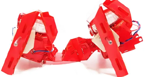
There are numerous techniques in design and fabrication of miniature robots including 3D printing [3], MEMS fabrication [4, 5], Inverse-Flow Injection (IFI) and Dip-Cure-Repeat (DCR) [6], photo-lithography [7], laser cutting and creat-ing multilayer composite structures with smart composite manufacture (SCM) [8] techniques. HAMR [9] and RoACH [10] are examples of such robots fabricated us-ing SCM fabrication method. Similarly, various types of materials, such as hydro-gels, polymeric elastomers [11], and PET films [12] are used to fabricate small-scale miniature robots. Origami-inspired robot fabrication [13,14], which consists of transforming a two-dimensional paper sheet into a three-dimensional complex design with subsequent foldings, is another method to manufacture miniature robots [15, 16]. Following the early works reported in [17], origami-inspired fab-rication method was first developed by researchers in Harvard University and MIT [18] and was later employed by many researchers in designing miniature grasping [19, 20], flying [21], and crawling robots [22, 23] as well as some legged versions [24]. Soft Modular Legged roBot (SMoLBot), shown in Fig. 2.1, whose main modules, as the fundamental base structures of the robot body, are fabri-cated using the same method of laser cutting and folding.
Studies on modular robots, classifies them into manual or autonomous re-configurable robots [25]. Both types preserve some advantages of modular robots, including but not limited to modifiable size scale, low weight, and low cost produc-tion. There have been various studies on self-reconfigurable robots autonomously changing shape to various configurations such as a quadruped or a snake [26], in which each module is provided with computational and communication capabil-ity. Similarly, there have been a tendency to use the reconfiguration capabilities of these robots as a locomotion mechanism for crawling-walking movement. Such robots use optimized shape change patterns to maximize the speed [27–29]. On the other hand, modular robots assembled by the operator have the advantage
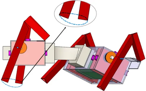
Figure 2.1: Soft Modular Legged roBot, SMoLBot.
of utilizing connection mechanisms that don’t need to be turned on or off. These connection mechanisms keep the manufacturing process of bigger structures sim-ple, straightforward, and time and cost efficient, and make it feasible to utilize various types of connection mechanisms such as electromagnetic connections [30] and electrostatic connections [31] in modular robot’s design.
Adaptability through mechanical compliance is an inherent advantage of soft robots, however, untethered actuation of soft miniature robots remains a chal-lenge. The Prospect of assembling soft and hard units in a modular concept can be a way to overcome challenges regarding the actuation and locomotion of the soft robots [32]. In a few researches, magnetic connections are used in soft com-plex robots connecting hard-driving units to the soft portion of the robot [33, 34] in a modular concept. Assembling soft and hard units, have granted the possibil-ity of manufacturing bio-inspired robot designs. For instance, an octopus inspired robot, which locomotes by pushing itself from the sea bed uses the same mod-ular and soft-hybrid concept to mimic a pattern that is similar to its biological counterpart [35].
Despite the evolution of modular robots, there exists a space for the development of a robot that carries features of different classes of robots as to be soft, foldable, and modular, simultaneously. SMoLBot is a foldable modular robot with soft connection mechanisms. SMoLBot’s design incorporates a fabrication method, that exploits features of origami-inspired foldable robots, such as low weight, low cost, easy-to-manufacture, high-structural-integrity, and simple replaceable structures. Similarly, with the use of PDMS connection mechanisms, SMoLBot turns to be soft and modular at the same time. Each module is made of a single acetate sheet with optimized fold-locks resulting in a highly resilient assembly, holding motors and electrical components. Each module consists of individually actuated and controlled DC motors, which allows various gait implementations and better locomotion. PDMS backbones make it possible to connect individual modules to each other while having the possibility of imposing different stiffness to the system. The main reason for designing a robot with individually actuated legs is not to claim that it is better or easier to control than miniature robots with coupled actuation but to enable gait modification during locomotion in a small scale. Next following sections will explain the design, manufacturing techniques, and evolution of SMoLBot.
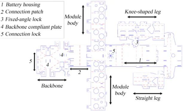
2.2
SMoLBot Design
SMoLBot’s modules are folded using 100-micrometer-thick flexible A4 size cellu-lose acetate sheets. The main structural material, as well as the compliant flexure joint design approach, are very similar to other miniature foldable robots such as MinIAQ [12]. In order to increase the structural integrity of the body, cer-tain folded structures such as T-folds and tab-and-fastener locking extensions are embedded into the original design. T-folds are out-of-plane extensions that have the capability of stiffening the body frame and acting as a beam between two vertical planes, as shown in Fig. 2.2. Tab-and-fastener extensions are U shaped fastener tabs, that keep the folded structures locked in place. A combination of rigid T-folds and tab-and-fastener mechanisms reduce the twist and buckling movement of the body. Enough space for two DC motors and a battery housing
is embedded between T-folds, and PDMS lock housings are embedded on the vertical stationary planes as shown in Fig. 2.2(b).
(a)
(b)
Figure 2.2: (a) AutoCad design and cut perspective of a folded robot. T-folds(1), motor housing (2), PDMS lock housing (3), leg locking patch (4), bottom patch and battery housing (5), top patch (6), left leg (7), right leg (8), rear patch (9), front patch (10), fastener and locks (purple), battery (green), PDMS locks (black), leg pin connections (blue), motors (black and grey). (b) Body design out-look.
Getting the smallest robot housing was aimed during the design process. A single frame of the module is approximately in the size of two DC motors (Pololu, Sub-Micro Plastic Plentary Geartmotor) and a single cell 3.7 Volt,150mAh Li-Po battery. Two DC motors are placed back-to-back and parallel to each other inside two tight circular openings on the T-folds. Battery is placed just under the motor
housing with T-folds holding it in-place (two pairs of T-folds are placed inside the body). Battery is easily accessible through the rear hatch door for charging or removal.
2.2.1
Material Selection
The primary aim while designing the multi-legged modular SMoLBot’s modules was to make an embedded single-piece crease pattern for ease of manufacturing. To select a proper material in terms of compliance, rigidity, and joint life-time, 100, 250, and 500-micrometer thick cellulose acetate sheets were selected (Fig-ure 2.3). During the manufacturing phase of SMoLBot, it has been observed that the thinner acetate sheets were easier to cut, fold and assemble. On the contrary, using thick films with higher structural rigidity makes the folding, and bending the sheet to form the corners difficult and time-consuming, particularly while scaling down to smaller-scale creases. Besides, the thicker sheets have lower joint performance; Flexure joints that are manufactured using thick acetate sheets would plastically deform, forming permanent fold-lines and break sooner than the joints that are made of thin-acetate sheets. Alternative materials can also be used such as Kapton® to achieve strengthened mechanical properties such as increased stiffness and higher joint cycle life.
2.2.2
Actuation Mechanism Design
Integrating a mechanism into a design, which has an elliptical trajectory and a simple unfolded form for locomotion is a challenge for foldable legged miniature robots. The flexure joints in foldable foot designs of the miniature robots have a limited degree of rotation, meaning that the joints deflection angle should be limited in a specific range to prevent shear at the joints. Leg actuation in SMoL-Bot is achieved by a four-bar mechanism that is cut and folded from the same sheet used for the body (Fig. 2.2(a)).
Figure 2.3: Various colors of 100µm thick A4-sized cellulose acetate sheets used to manufacture module frames of SMoLBot.
Figure 2.4 shows the folding procedure of an actual leg and its generalized four-bar model. SMoLBot’s feet are modeled as a four-four-bar linkages, overall with a single degree of freedom (DOF). Each leg is connected to the main body through a one-DOF rotational 3D-printed cam-shaft and fold-locks. 3D-printed cam-shaft construct a tight-fit connection between the DC motor and the foot. Triangular beam shaped parts of the folded leg are the rigid links and single thin plate in the middle acts as the flexure joint. In this configuration, the beam’s rigidity is dependent on its length, width, thickness, and Young’s modulus of material used [36]. Joint width, length, thickness, and maximum deflection angle can be optimized to increase the fatigue life cycle of the flexure joints, by distributing the load more uniformly and reducing the stress at compliant joints. Furthermore, it is important to note that the robot’s locomotion is affected by small alterations in the dimensions of the flexure joint of the folded leg; i.e. changing the width or length of the thin plate changes the stiffness of the joint that result in a different locomotion pattern.
With an initial assumption of known planar coordinates of the feet attachment points to the body, motor locations, and cam-shaft length, kinematic analysis of the foot is conducted to determine the unknown parameters such as the positions
Figure 2.4: Leg’s folding step-wise process.
of the contact points, the deflection angles, and the velocities. For SMoLBot’s feet, a simple four-bar cam-driven mechanism was designed and synthesized by altering the dimensions of the foot, the position of the joints and radius of the cam (input crank link) in order to obtain an acceptable gait path to form a maximum contact to the ground with a relatively long stride length and acceptable foot lift, as shown in Fig. 2.5. The selected four-bar is not optimal performance-wise; However, its simplicity was favored over the complexity of the compound planner foldable assembly.
2.3
Backbone Design
Backbones can be categorized into three different types, namely: continuous, discrete, and hybrid [37]. Robotic systems with continuous backbones (referred as continuum robots) often only use elastic materials for the robot’s structural parts [38]. Robotic systems with discrete backbones use articulated linkages as connection mechanisms, and hybrid mechanisms similarly utilize a mixture
Figure 2.5: Gait trajectory of the cam-driven four-bar mechanism of SMoLBot. of elastic elements and linkages to achieve a relative motion between the body modules neighboring the backbone.
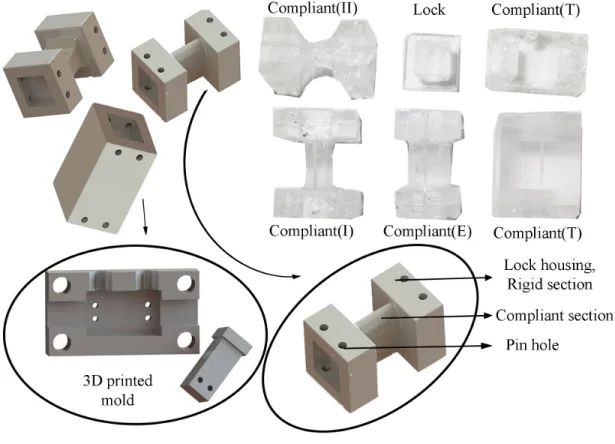
We designed an easy-remove-easy-assemble connection mechanism that can be embedded to the foldable body, using puzzle shaped molds. 3D-printed molds with diverse shapes and sizes based on the backbone’s intended stiffness, have been used in the molding process, an example of such molds is shown in Fig. 2.6. Manufacturing backbones with different designs and stiffness values are possible with this fabrication method. Structural and geometrical factors have a great effect on the moment of inertia. The shape of the backbones have been modi-fied as a means to achieve desired stiffness values. We designed and categorized SMoLBot’s backbones based on their overall geometric shapes. Connection as-sembly consists of two individual pieces, the backbone connecting two individual modules to each other, and the locking mechanism connecting each module to the backbone. PDMS is used for manufacturing both the backbone and the lock-ing mechanism. PDMS locks are fixed inside the modules in order to avoid any undesired movements, and pins are used to fix the PDMS locks to the backbones. Slots for pin connections have been embedded on both the PDMS lock and the backbone molds during the molding process with circular cuts. This connection mechanism between the locks and the backbone makes the lock and backbone
mechanism feasible for easy-remove-easy-assemble operation purposes.
The need to eliminate module collisions sets a minimum for the length of the backbone and the desired stiffness values at different axes change the backbone cross-section shape and dimensions. The initial dimensions of the backbones have been derived using beam stiffness relations with intended stiffness and Young’s modulus of the PDMS. PDMS Young’s modulus is dependent on its mixing ratio and curing temperature [39,40]. In order to manufacture connection mechanisms, PDMS is mixed with 5:1 and 1:10 ratios, and is poured into the 3D-printed PLA molds, and baked in temperature of 65◦C for two hours [41].
Figure 2.6: PDMS locks and PDMS backbones: only torsional, compliant I-beam and compliant with elliptical mid-cross-section.
SMoLBot’s backbones are categorized into two main classes: rigid and compliant. Rigid backbones are a solid block of PDMS with metal pin insertions possessing the highest bending and torsional stiffness in all directions. Compliant backbones are grouped into four different types: backbones with only torsional deflection,
very soft backbones, medial-soft, and soft backbones. Backbones are constructed from three different sections, two of which acts as PDMS lock and one section that defines the overall stiffness of the backbone. Locks are rectangular-shaped holes embedded at the two ends of the PDMS backbone. PDMS locking mechanisms embedded inside each module are placed inside these holes and are mounted to the backbones using pins. Mid-section shapes of the backbones are chosen considering the intended overall stiffness of the backbone. Backbone’s stiffness is controlled with geometric factors using the width, the length, and the height of the mid-section. Table 2.1 shows the bending and torsional stiffness of the backbones used in SMoLBot. Rigid backbone is fully stiff PDMS blocks with metallic insertions. Remaining backbones are manufactured using only PDMS molded in 3D-printed molds. Compliant backbone (I) and (II) are I-beam backbones with different rectangular cross-sections, compliant(E) is the I-beam backbone with an ellipti-cal cross-section and compliant(T) is a rectangular solid block with only torsional deflection. Compliant(T) backbones have the highest bending stiffness compared to the compliant(I), (II), and (E) backbones; however, since the torsional stiff-ness values of the compliant(T) backbones are lower than the backbone’s bending stiffnesses, modules still have limited rolling behavior, and that is the reason to call these rectangular prisms as only torsional backbones. Compliant(E) back-bones with elliptical mid-cross-section possess higher torsional stiffness compared to the compliant (I) and (II) backbones. Two rectangular I-beam cross-sections with different width are used to manufacture compliant (I) and compliant (II) backbones. The compliant(II) backbones are rectangular I-beams that posses bigger length and width compared to the I-beam compliant(I) backbones.
Torsional stiffness of the compliant backbones are determined using (2.1) - (2.3), as follows:
kt = c2Gab3/L, (2.1)
kt= Ga3eb3e/L(a2eb2e). (2.2)
the length of the part, and c2 is the correction coefficient as explained in [42].
Similarly, ae and be are defined for the backbones with elliptical cross-sections
and are the semi-minor and semi-major lengths of the ellipse. Overall torsional stiffness of the backbones with varying cross-section is given by:
k−1t total = 3 X n=1 1/ktn (2.3)
in which ktn is the torsional stiffness of each section on the backbone and kttotal
is the overall torsional stiffness of the backbone. Equivalent bending stiffness for the backbones with varying cross sections can be found by integrating the beam bending equation over the length, as follows:
kbi = Z L 0 M (x) EIi(x) dx, i = [1, 2] (2.4)
in which E is the Young’s modulus, I is the moment of inertia for corresponding section, M is the moment, and kbi is total directional bending stiffness. Subtitles
i = 1 and i = 2 show the directions of the bending stiffness and moment of inertia along the width (i = 1) and height (i = 2) of the backbone.
Table 2.1: BACKBONE STIFFNESS
Backbone kt (Nm/Rad) kb1(Nm/Rad) kb2(Nm/Rad)
Rigid ∞ ∞ ∞
Compliant(T) 0.075 0.669 0.669 Compliant(I) 0.015 0.090 0.043 Compliant(II) 0.017 0.107 0.071 Compliant(E) 0.045 0.258 0.165
2.3.1
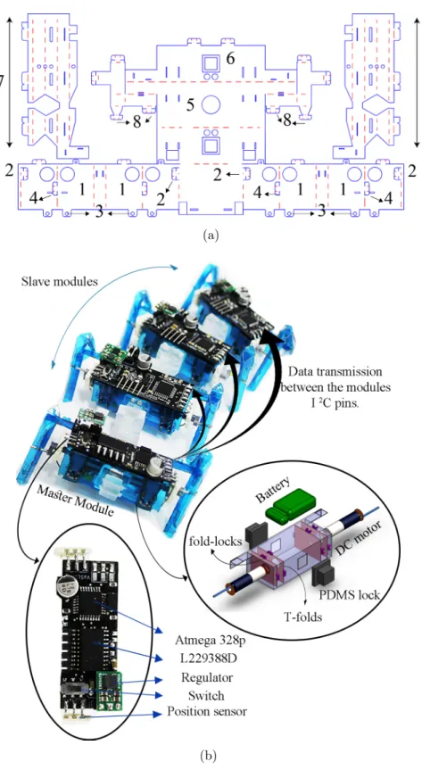
Electronics and PCB Design
With the intention of independent control and actuation of each module, each individual module has a printed circuit board (PCB), that has the same width
and length as a single module. Each module in SMoLBot has two lightweight DC motors that are individually controlled and each motor is driving a single leg. The PCB has an Atmega-328P as the main controller, along with one L293DD motor driver that is able to drive two DC motors. In order to control the speed and position of the DC motors, two position sensors, Bourns Potentiometer 3382 series, are placed on the PCB, and connected to the motor shafts with a 3D-printed cam-shaft. To run the robot, a single cell 3.7 V, 150 mAh LiPo battery is used for each module. Voltage is boosted up to 5 V with a step-up regulator, located on the top layer of the PCB, powering the micro-controller, the motor driver, the sensors, and the DC motors.
Figure 2.7: SMoLBot’s real PCB and Eagle board schematics. Green colors show the pin hole insertions and red rectangular plates show the solder patches.
2.4
Fabrication and Assembly
After finalizing the PCB and soldering the electrical components, each module is fabricated and assembled. The fabrication process begins with the laser cutting of the crease pattern on the cellulose acetate sheets with a laser engraver (Universal Laser systems, VLS 3.60) and then folding. Body and locomotion mechanisms consist of consecutive foldings of T-folds and tab-and-fasteners, that transform the two-dimensional planar design to a three-dimensional complex shape. The first step in assembling SMoLBot is folding the T-shaped plates that are labeled as ’1’ in Fig. 2.8(a). Next, T-folds are fastened by using double-sided tab-and-slot fasteners (Fig. 2.8(a)-2). Then, the extension tabs, labeled as ’3’ in Fig. 2.8(a), are attached to the front and back of the main-frame. The top cover
(Fig. 2.8(a)-5) of the frame is folded next and locked on the T-folds by using the U-shaped fasteners existing on top of the T-folds (Fig. 2.8(a)-4).
The next step is placing electronics, DC motors, and PDMS locks inside the robot housing and closing and fastening the rear hatches (Fig. 2.8(a)-6). Then the leg mechanisms (Fig. 2.8(a)-7) are folded and fixed to the body with fasteners provided on the top surface (Fig. 2.8(a)-8), separately. Lastly, I2C pins of the
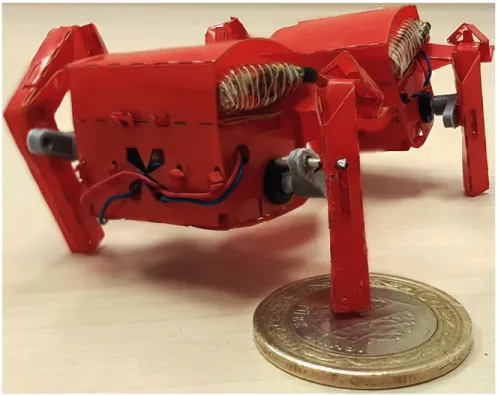
PCBs are connected using thin wires. The assembly time for each module is about 40 minutes, and the folded structure of each module is approximately 16 mm long, 44 mm wide, 15 mm high. Each module is about 18 g in total, 2 g of which is the structural part, 2.5 g DC motors, 5 g battery and 8.5 g that consist of the board and electrical components and pins.
2.5
C–SMoLBot Design
Primarily, C–SMoLBot and SMoLBot are designed to only differ in their foot designs so as to have robotic platforms to compare the performance of the robot with two different feet types. C–shaped legs provide the robot a high mobility, high maneuverability, and better climbing and rough terrain performance. Addi-tionally, combining characteristics of the soft materials with C–shaped leg designs in robots with soft backbones would result in a system with higher maneuverable and operational capabilities. C–SMoLBot’s main body design, electronics, and control strategy are identical to that of SMoLBot’s but its legs are fabricated and assembled as separate parts and added to the mainframe of each module at the last step of the robot assembly.
C–SMoLBot main module frames are similar to SMoLBot and are cut and folded from cellulose acetate sheets. The two-dimensional unfolded technical drawing cut file of the mainframe of the C–SMoLBot can be seen in Fig 2.9. The only difference in the module design is the absence of the feet connection patches, since C–SMoLBot does not have compliant feet mechanisms, and the connection between the module frame and the feet are done using camshafts. 3D-printed
(a)
(b)
Figure 2.8: (a) SMoLBot’s AutoCAD design (b) Eight-legged four-module SMoL-Bot and a single module’s exploded view with electrical components.
cam-shafts are designed to build the connections between the module body and the C–shaped feet with a tight-fit insertions holding the position sensors as well.
Figure 2.9: Schematics of the C–SMoLBot’s AutoCAD module design.
2.5.1
C–shaped Leg Design
Robust structure, fast running, better in-place turning, easier steering, and ob-stacle scaling capabilities make C–legged robots applications to have much higher levels of adaptability in different environments. C–shaped leg design would allow the body to adapt to the surface conditions without requiring much control effort, which was first introduced in Rhex [43]. Simple half-circle shaped design similar to the C-leg model in Rhex is used to manufacture the C–SMoLBot’s feet. In order to investigate the effect of feet compliance in the miniature robot’s locomo-tion and their climbing capabilities, two different types of soft and hard feet are used in the C–SMoLBot experiments. Hard feet are 3D-printed structures coated with PDMS and soft feet are manufactured using PDMS with a mixing ratio of 5:1. Avoiding any collision between two individual feet on consecutive modules and obtaining a range of stiffness that can carry the weight of the module are two main parameters that affect the dimensions of the foot. The need to eliminate module collisions sets a maximum radius length of the foot which is defined based on the length of the backbone and the module, and the intended stiffness range of the foot defines the thickness of the C-shaped leg. Two different feet types of the C–SMoLBot are shown in Fig. 2.10.
Figure 2.10: C–shaped 3D-printed and PDMS feet with 3D printed cam-shaft extensions.
Long half-cylindrical parts of the feet in Fig. 2.10 are the cam-shafts that make it feasible to connect the feet to the motors. 3D-printed cam-shafts are placed inside the 3D-printed molds before curing the PDMS feet to make a tight-fit connection between the PLA and the PDMS. A single foot in C–SMoLBot is 4 mm-thick half-circle with inner and outer radiuses of 5.5 mm and 12 mm, respectively.
2.5.2
Performance of C–SMoLBot
Headmost experiments of the multi-legged C–SMoLBot are done to measure the translational velocity of the robot and to observe the obstacle climbing perfor-mance of the C–SMoLBot (Fig. 2.11). Experimental results are inspected to compare the maneuver and climbing potentials of the legged and C–legged SMoL-Bots. Additionally, a study investigating the effect of soft C–shaped feet on the robot’s locomotion is conducted as well, comparing the results in soft C–shaped with hard C–shaped feet.
Figure 2.11: Six-legged three-module C–SMoLBot obstacle climbing experiment.
2.6
Evolution of SMoLBot
This section will demonstrate briefly the earlier versions of the robot and SMoL-Bot’s design evolution.
2.6.1
Body and Leg Mechanisms
With the intention of obtaining the smallest possible module frame, different frame designs that each uses various positioning combinations of the components (DC motors and battery) were considered. In earlier versions of SMoLBot, the motors were placed parallel on top of each other and the battery was placed on top of the module inside a rectangular housing structure. One of the earliest versions of SMoLBot where the DC motors are placed on top of each other is shown in Fig. 2.12.
Using the design concept mentioned earlier, we were able to manufacture mod-ules that are almost in the half size of the latest version of SMoLBot. However, the initial robot configuration requires designing two different four-bar leg mech-anisms for the right and left legs due to the miss-alignments of the motors. Using four-bar leg design formulations and an optimization technique, it was possible to achieve two different leg designs that have similar trajectories, shown in Fig.
Figure 2.12: Old version SMoLBot with two different four-bar (right and left) feet designs.
(a) (b) (c)
Figure 2.13: (a) Non-straight knee-shaped four-bar leg. (b) Straight four-bar leg. (c) Trajectory of the knee-shaped and the simple four-bar legs of the old version SMoLBot.
2.13(c). The first leg model is a simple straight leg design, shown in Fig. 2.13(a), and the other leg is a non-straight knee-shaped design with a fixed locking angle, shown in Fig. 2.13(b). The proposed design for the knee-shaped link consists of two regular triangular beams connected with a short flexure joint and an in-clined fixed-angle tab-and-fastener. It should be noted that the angle between the inclined fastener and the leg on the unfolded structure is equal to the resulting desired fixed-angle lock between the folded beams. Even though it was possible to achieve feet trajectories that are similar to each other, straight walking/running locomotion was not achieved. This was the reason to design the latest version of SMoLBot with a slightly bigger module frame but similar left and right feet, that eliminates the revolving motion of the robot.
2.6.2
Backbones
The initial version of the backbones were cut and folded using the same acetate sheets that are used to manufacture the modules (Fig. 2.14). Backbone designs consist of consecutive folds that form three-dimensional mechanisms that inte-grate rigid structures to the soft plates in order to achieve an extra DOF in a specific direction. Acetate sheet backbones were categorized into three different types: stiff, 1-DOF, and 2-DOF (Fig. 2.15). Acetate sheet backbones are placed on the rear patches of the modules and are connected to the second module using fold-locks. Stiff backbones are square cylinder-shaped structures that possess the highest bending and torsional stiffness, and compliant acetate sheet backbones are a combination of folded prisms and thin plates. The number of the plates in different directions determines the DOF of the compliant acetate sheet back-bone. 1-DOF backbone has only one compliant plate in only one direction and the 2-DOF backbone possesses two plates in two perpendicular directions.
Foldable compliant backbones have two major problems; First, minimizing the di-mension of the backbones is not possible, i.e. scaling down the compliant patches increases the stiffness of the backbone and makes the folding process longer and
Figure 2.14: Old version SMoLBot’s AutoCAD design with a 2-DOF acetate sheet backbone.
even sometimes impossible. The second problem is related to the nature of the manufacturing method of the foldable backbones, in which the fold lines play an important role in manufacturing an origami structure. Appearance of the per-manent fold lines on the compliant patches due to the tension and compression forces, eliminates the elastic behavior of the foldable compliant backbone (Fig. 2.16) and results in the robot’s failure. This problem was observed shortly in all foldable compliant backbones during the robot’s operation due to the periodical compression-tension bending motions. Failure of the foldable backbones during the operation was the main reason to modify the backbone’s design. Two main factors are considered while manufacturing the new backbones: the possibility of modeling the backbone and changing the stiffness values easily. The concept of manufacturing backbones using PDMS, enables imposing different stiffness val-ues to the system by simply changing the backbone’s geometrical dimensions, and makes it possible to model the backbone using the beam’s theory and the PDMS properties.
(a) (b) (c) (d)
(e) (f)
Figure 2.15: (a) Stiff acetate sheet backbone’s AutoCAD design, and (b) real Stiff acetate sheet backbone. (c) Foldable 1-DOF acetate sheet backbone’s AutoCAD design, and (d) real foldable 1-DOF acetate sheet backbone. (e) Foldable 2-DOF acetate sheet backbone’s AutoCAD design, and (f) real foldable 2-DOF acetate sheet backbone.
Figure 2.16: Operation failure of a four-legged two-module initial version SMoL-Bot with 2-DOF foldable compliant backbone.
Chapter 3
Operation and Control
This chapter discusses the control strategy of SMoLBot and briefly demonstrates the dynamic locomotion parameters of the robot with different backbones and module numbers, on a terrain. The motors used in SMoLBot do not have any feedback sensors attached. Therefore, low-cost position sensors, Bourns Poten-tiometer 3382 series, are used for the position and the velocity control of each leg. To achieve gait synchronization with specific constant feet phases, legs are controlled using two parallel PD control loops: one controlling the position of the motor and one controlling the velocity.
3.1
Controller Design
With an aim to study the effect of the number of legs on miniature modular robot’s locomotion and in order to investigate the motion behavior of the robot with various types of backbones while operating with distinct combinations of running/walking gaits, each leg is actuated and controlled individually. The sig-nal from each sensor is used to estimate both the frequency and the phase of the motors with respect to the main reference signal. Since sensors used in SMoLBot are position sensors with 330◦ output range, motor speeds are calculated at each
controller loop only within the controllable range of the cycle to avoid system fail-ure in 30◦ sensor dead range. The controller reference signals consist of two main parameters: the desired stepping frequency and the desired position. Both these parameters are chosen, based on the gait that is being studied and the desired translational velocity of the robot. The electrical connections between different modules are done by using I2C pins of the micro-controllers. Instantaneous value of reference signal generated in the leader module is transferred to all remaining modules which are referred to as the follower modules. Step-wise process of the control stage can be summarized as follows:
1. Gait is defined by the operator.
2. Desired frequencies are imposed to the system by the operator. 3. Reference signal is generated in the leader module.
4. Desired phase differences and frequencies of the legs are transmitted to the follower modules.
5. Instantaneous value of the reference signal is transferred to the follower modules.
6. Motors are individually controlled with PWM signals, based on the refer-ence signal with two parallel controller loops for the frequency and position.
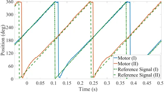
Steps 1 - 4 are executed only once in the beginning and their outputs are stored in the main code, remaining steps are continuously executed in each loop for controlling purposes. A modified PD controller similar to [44] is used to control the motor positions, which uses two parallel PD control loops for the position of the motor and the estimation of the velocity as in (3.1). Reference tracking of two motors with 0 and 180◦ phases (trot gait) can be seen in Fig. 2.7. Trot gait is a quadruped gait where diagonal legs are in phase and two side-by-side pair legs are 180◦ apart in phase.
P W Mi = P W Mi−1+ kpf rq.Ef rqi + kdf rq.(Ef rqi − E i−1
f rq)+ (3.1)
kppos.Eposi + kdpos.(Eposi − E i−1 pos)
where, the superscripts i and i − 1 correspond to the current and previous step values, and the subscripts pos and f rq denote position and frequency related parameters. E shows the error between the current value and the desired one. kp
and kd are the proportional and derivative gain of the controller.
Figure 3.1: Controller output for two DC motors with π phase difference. In Fig. 2.7 dash lines are reference signals with the phase difference equal to 180◦. The results are obtained using serial communication between the Arduino
on the PCB and MATLAB, demonstrating the reference signals and the sensors’ output showing the motors’ real-time positions.
3.2
Performance of SMoLBot
3.2.1
Operation and Experiments
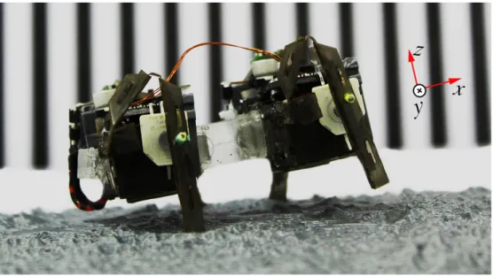
The first experiments on SMoLBot are designed to observe the effect of the back-bone stiffness on the smoothness of the robot’s locomotion. The experiments are run with two and three-module robots with rigid backbones and compliant backbones. The robots are run with trot gait at 2 Hz stepping frequency on smooth and rough surfaces and the roll and pitch angles of the robots, as well as their translational velocities, are compared. A picture of a four-legged two-module SMoLBot walking on rough terrain is shown in Fig. 3.2, in which the surface used is a 1 : 10M scaled version of the NASA Shuttle Radar Topographic Mission 90M elevation data for Oregon [45].
Figure 3.2: The rough terrain locomotion of four-legged two-module SMoLBot with rigid backbones.
(a)
(b)
Figure 3.3: (a) Center of gravity detection and pitch angle measurement of the four-legged two-module SMoLBot with compliant(E) backbone. (b) Crawling four-legged two-module SMoLBot with compliant(I) backbones and zero pitch angle.
(x) and width (y) of the robot; these axes are shown in Fig. 3.2. Orientation and velocity data are obtained using raw videos showing the robot from side, front, and top. Roll and pitch angles are measured using front and side view videos, respectively. Top-view videos are used to detect the robot’s center of gravity in the xy plane and to measure SMoLBot’s velocity.
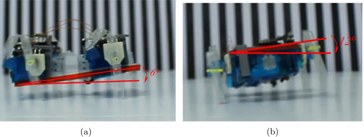
The difference of pitch and roll angles of the four-legged two-module SMoL-Bots with compliant(E) and rigid backbones can be seen in Fig. 3.4 and 3.5, respectively. The four-legged two-module robot with compliant(E) backbone (SMoLBot2(E)) has smoother walking behavior compared to the four-legged
two-module robot with a rigid backbone (SMoLBot2(R)) on smooth terrain. The
re-sults show that the roll angle variation during locomotion is reduced from 10◦ to 7◦and the pitch angle variation decreased from 12◦to 6◦switching from the rigid backbone to the compliant one for SMoLBot2. Four-legged two-module robots
with compliant backbones conform to the surface better because of the body undulations and the torsion between the two modules, resulting in a smoother locomotion.
Figure 3.4: The pitch angle of four-legged two-module SMoLBot with rigid and compliant backbones on smooth terrain that are operating with a trot gait.
Figure 3.5: The roll angle of four-legged two-module SMoLBot with rigid and compliant backbones on smooth terrain that are operating with a trot gait.
(a) (b)
Figure 3.6: (a) Pitch angle measurement experiment of SMoLBot with compli-ant(E) backbones. (b) Roll angle measurement experiment of SMoLBot with rigid backbones.
Table 3.1: TRASNLATIONAL VELOCITIES OF THE FOUR-LEGGED TWO-MODULE AND SIX-LEGGED THREE-TWO-MODULE SMoLBotS
Robot SMoLBot2(R) SMoLBot2(E) SMoLBot3(R) SMoLBot3(E)