Development of Micro-Structured Metamaterials
for Innovative Antenna Layouts
Filiberto Bilotti1, Filippo Capolino2, Ramon Gonzalo 3, Ekmel Ozbay 4, Jordi Romeu5, Alex Schuchinsky6, Sergei Tretyakov7, Yiannis Vardaxoglou8
1
Department of Applied Electronics, University of Roma Tre, Italy 1[email protected]
2
Department of Information Engineering, University of Siena, Siena, Italy 3
Public University of Navarra, Antenna Group, Campus Arrosadia, 31006, Pamplona, Spain 4
Nanotechnology Research Center, Bilkent University, Ankara, Turkey 5
AntennaLab – TSC, Universitat Politècnica de Catalunya – UPC, Barcelona, Spain 6
School of Electronics, Electrical Eng. & Computer Science, Queen’s University Belfast, UK
Abstract— In this paper, we present the joint activities developed
in the frame of the FP6 European Network of Excellence METAMORPHOSE in the field of new micro-structured materials for antenna applications. One of the key scientific goals of the research efforts developed within this network is to design innovative micro-structured materials to improve the performances of conventional radiators. Miniaturization, multi-functionality, reduced interference with electronic circuitry, are some of the main challenges in the design of antennas for the next generation of electronic transceivers in the microwave frequency range. The employment of different classes of metamaterials in innovative antenna layouts has been demonstrated to be effective to reach most of the desired goals. The theoretical, numerical and experimental efforts carried out by the leading European institutions working in this field, in fact, show how metamaterial antennas with unusual features are ready to push the innovation in the antenna research. The collaborative dimension of this research is described in this paper, as well as the related scientific achievements.
I. INTRODUCTION
The recent quick development of electronic and telecommunication systems requires ever smaller radiators. Miniaturization, multi-operation, multi-functionality, reduced interference with nearby circuits, greater performances in terms of efficiency and directivity are some of the main challenges in the present and future antenna design.
Whatever is the application, miniaturized antennas are always an industrial need in mobile and satellite communication systems. However, despite the efforts and the progresses in the antenna design, the radiator still represents the most bulky electronic device of a (micro-)system.
Significant efforts have been devoted in the past to achieve low-power miniaturized electronic and RF components. Low-power modules require high-efficient low-loss miniaturized components and high-impedance solid state devices are the best solution to minimize power consumption. The size reduction of micro devices, in fact, leads to low bias currents
and high impedance terminations (e.g. in MEMS we have even 10 k:). In order to integrate antennas on a chip, together with the remaining circuitry of the front-end of micro-systems, miniaturized antennas with the desired features (small dimensions, high input impedance, etc.) are needed, while not being readily available. In addition, nano-scale devices based on Carbon Nano Tube (CNT) high-speed transistors or nano-scale MESFETs are emerging as the new technology for very fast and very low-power devices, exhibiting also high-impedance terminations. Also in this framework miniaturized high-impedance antennas will be needed.
As far as small antennas are concerned, the fundamental limitations on the bandwidth, gain, and efficiency have been analytically related to the antenna size [1]. Different standard techniques have been used to reduce antenna size, but they have important drawbacks: the employment of high-epsilon materials leads to poor efficiencies and bandwidths; ceramic materials cannot be easily integrated in current circuit technology; slotted or irregularly shaped antennas show very little versatility and the design is based on heuristic techniques; the employment of Genetic Algorithms and optimization tools results in irregular antenna shapes, with the consequence of a weak control on the pattern shape and on the radiating antenna performances.
Multi-functionality and reduction of the interferences between the antenna and the circuitry residing in close proximity are other faces of the same medal. When integrating the antenna in a complex micro-system, in fact, the reuse of the radiating components for different services and the minimization of the cross-talk with other circuits placed at very short electric distances become unavoidable issues to be considered.
The challenges coming from this new scenario can be successfully taken by using proper micro-structured metamaterials, which are able to make the antennas smaller and smaller and to enhance their basic performances. The 7
TKK, Helsinki University of Technology, Finland 8
Dept. of Electronic and Electrical Engineering, Loughborough University, UK
978-2-87487-001-9 © 2007 EuMA October 2007, Munich Germany
Proceedings of the 37th European Microwave Conference
challenging nature of this research needs the cooperation among theoretical, numerical and experimental expertises in the broad field of metamaterials. The aim of this paper, thus, is to present the collaborative work done in this specific field in the framework of a research project supported by the METAMORPHOSE Network of Excellence (NoE).
II. RESEARCH ACTIVITIES
The goal of this research is to propose the design of innovative micro-structured metamaterials based on resonant and non-resonant magnetic inclusions, such as magneto-dielectrics, Mu-NeGative (MNG) metamaterials, and metasurfaces, to improve antenna miniaturization and enhance multi-functionality. The research activities we will detail in the following sub-sections are articulated in four main tasks: a) design of miniaturized magnetic inclusions; b) design of MNG and magneto-dielectric substrates for miniaturized patch antennas, c) design of magnetic inclusions as covers and reflectors for dipole antennas; d) design of metasurfaces for enhanced radiation properties.
Artificial magnetic materials (AMMs) have been theoretically shown to be very useful in the design of patch antennas with reduced dimensions when they are combined with other materials [2] or contain natural magnetic inclusions [3]. AMMs are obtained by including proper magnetic resonant particles in a host dielectric. If the dimension and the separation between the inclusions are both small compared to the wavelength, the artificial material can be described through a macroscopic permeability, whose typical behaviour is reported in Fig. 1.
Fig. 1 Typical variation of the macroscopic permeability of an artificial medium made by resonant magnetic inclusions (from [5]).
The frequency region below the resonance refers to the magneto-dielectric materials, having a high and positive real part of the permeability. The narrow window around the resonance describes, instead, the behaviour of the Artificial Magnetic Conductor (AMC) or High Impedance Surface (HIS) region, where the material resembles a Perfect Magnetic Conductor (PMC). Just above the resonance, the real part of the permeability is negative, describing, thus, the MNG metamaterials. Finally, another class of interesting artificial materials is the one exhibiting a close to zero (Mu-Near Zero – MNZ materials) permeability.
A. Design of miniaturized magnetic inclusions: analytical models and experimental verification
In order to reduce the antenna dimensions by using AMMs, a required preliminary exercise to be done is the miniaturization of the inclusions to be used. Miniaturized magnetic inclusions can be obtained by using Multiple Split-Ring Resonators (MSRRs) and Spiral Resonators (SRs). New and accurate analytical models for a quick design of such inclusions have been developed by the group of Roma Tre [4]. The comparison with full-wave simulations confirms the effectiveness of the models and the experimental verification is currently on the way in collaboration with the group of Bilkent [5]. SRs are also fabricated in UPC (see Fig.2) and also in this case numerical simulations and measurements are in a good agreement. Further degrees of freedom in the design of miniature SRs can be obtained by means of complex shapes. This part of the work is conducted in QUB and the results show that the properties of SRs can be efficiently controlled by independent variations of internal magnetic and electric couplings and the structure geometry.
Fig. 2: Two different implementations of SRs fabricated at UPC (from [6]).
B. Design of MNG and magneto-dielectric substrates for miniaturized patch antennas
Recently, some theoretical works have shown the possibility to realize sub-wavelength patch antennas with AMMs [2]-[3]. In [2] it has been shown how circular patch antennas can be made very small compared to the operating wavelength, by pairing ideal isotropic and homogeneous MNG materials and regular dielectrics. When going towards a practical realization of the MNG metamaterial through proper resonant inclusions (see Fig.3), the issues related to the anisotropy of the actual material can be neglected [7]. In order to reduce the size of the inclusions required by the small thickness of the substrate of a patch antenna, the group of Roma Tre has proposed to employ the SRs designed according to the model proposed in [4].
Fig. 3 Model of a patch antenna loaded with magnetic inclusions (from [7]).
The numerical simulations of the structure, made through CST Microwave Studio®, show a perfect agreement with the theoretical expectations [7]. The field distribution underneath and the current density on the patch exhibit the same
behaviour in the two cases. The resulting matching features and patterns are reported in Fig.4. A Ȝ/25 patch antenna with reasonable efficiency (67%) and good gain (3.4 dBi) has been demonstrated. This antenna is going to be fabricated in the present collaborative project by the group of Bilkent.
0.0 0.5 1.0 1.5 2.0 2.5 3.0 -25 dB -20 dB -15 dB -10 dB -5 dB 0 dB R e turn Lo ss [dB ] Frequency [GHz]
Fig. 4 Return loss and patterns of the subwavelength patch antenna (from [7]).
Another way to obtain miniaturized patch antennas without perturbing too much the remaining features of the antenna is to employ composite magneto-dielectric substrates with natural magnetic inclusions [3]. Fig. 5 illustrates the results for an antenna filled with a magnetic composite material containing thin iron sheets separated by dielectric spacers.
Fig. 5 Return loss of a miniaturized patch antenna as compared with the dielectric-filled antenna (from [3]).
C. The role of magnetic inclusions in the design of covers and reflectors for dipole antennas
Magnetic inclusions working at the resonance frequency can be used to obtain AMC reflectors. In this case, in fact, an electric source (e.g., a dipole) can be placed in a close proximity of the reflector, reducing, thus, the space occupied by the whole radiator. The group of UPC has proposed the employment of inexpensive continuous aluminium profiles with a split-ring shaped cross section to realize AMCs [8]. A proper experimental verification of the radiation of a dipole in close proximity of this reflector has been conducted, as seen in Fig.6. The dipole radiation above the AMC is enhanced while reducing the profile of the whole system, when compared to a metallic ground plane. The same group has proposed the employment of SRs as magnetic inclusions for a multifunctional reflector, working either as an AMC or a Perfect Electric Conductor (PEC) plate. This property has been studied in [9] for the Capacitively Loaded Loop (CLLs) case, and states that this type of AMC slabs behave as PMC
when the incident electric field impinges on one side, and as a PEC when the incidence is on the opposite side of the slab. The measured phase of S11 and S22 is plotted in Fig.7.
Fig. 6 H-plane radiation pattern of a dipole at 1 mm above of the split-ring continuous AMC and the comparison with a PEC ground plane at 2.6 GHz. On the left, there is a detail of the fabricated structure.
Also in this case, the behaviour of a dipole radiating above this structure has been proposed (Fig.8), showing a profile reduction when comparing the dipole over the SR AMC surface at 5 mm, and over a regular PEC at 25 mm (i.e. O/4).
2.4 2.6 2.8 3 3.2 3.4 -180 -135 -90 -45 0 45 90 135 180 Measured Phase S11-S22 Frequency (GHz) P has e ( degr ee) Measured S11 Measured S22
S11~PMC
S22~PEC
Fig. 7: Measured phase of the S11 and S22 parameters, showing the dual behaviour of the SR AMC surfaces (from [6]).
H plane
Fig. 8: Detail of the SR AMC surface with the dipole (left), and radiation diagram (right), comparing the results over the AMC at 5 mm (solid line) and over the ground plane at 25 mm (dash-dotted line) at 2.9 GHz (from [6]).
In the same framework, the groups of Roma Tre and Siena are investigating the behaviour of an electric source in presence of a reflector (or a cover) made by resonant magnetic inclusions. Investigations based on both theoretical predictions derived through simple engineering formulas and full wave results with commercial software and ad-hoc fast solvers are being carried out. The fast solver is able to model efficiently a periodic substrate of several Split Ring Resonators (SRRs) with a radiating metallic dipole on top. As an example, in Fig. 9 it shown the radiation pattern of a short dipole with length Ȝ0/9 on a wall made by two layers of SRR, similar to the one in [9]. The dipole is located at a distance of
Ȝ0/8.5 from the SRR wall. Note the absence of secondary peaks and the low back radiation. Furthermore, preliminary results show an input resistance of 6-7 Ohms, which is larger than that of such a small dipole in free space. It has been shown also that the presence of a wall made by SRR may act as a multi-functional radiator pointing towards opposite directions, depending on the resonance or out-of-resonance behaviour of the SRR reflector/cover.
f = 13.73 GHz, Substrate: array of 33x11 SRR cells
-80 -70 -60 -50 -40 -30 0 15 30 45 60 75 90 105 120 135 150 165 180 Theta (degrees) R adi a ti on P at ter n ( dB ) H-Plane E-Plane zz Short dipole
Fig.9 Radiation pattern of a Ȝ0/9 dipole over a 33x11 cell SRR bi-layer.
D. Design of metasurfaces with enhanced radiation properties
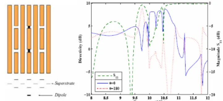
The main goal of this part of the project, conducted jointly by UPNa and Loughborough, is the design of metasurfaces capabale of increasing the directivity of standard dipoles. The meta-superstrate configuration is based on two parallel dipoles and a continuous wire [10], as it is shown in Fig. 10a. This unit cell has a pass-band and a stop-band frequency. Tuning a dipole to the pass-band frequency of the superstrate, the directivity and efficiency of the whole system, i.e., dipole antenna plus meta-superstrate will be enhanced. The physical dimensions are as follows, the length of the dipoles is ld=9.17 mm, the thickness of the dipoles and wires t=0.8 mm, the dielectric constant Hr=2.2, the copper cladding p=17 μm, the lattice constants a=1.6 mm and b=10.17 mm, the vertical distance 2h=1.57 mm and distance from the dipole to the superstrate 1.01 mm. As it can be observed in Fig. 10a, the dipole is placed behind the cut wires so that the current induced in the short dipoles goes in phase with the current of the radiant dipoles. This allows to place the dipole very close to the meta-surface without losing radiation efficiency. The thickness of the whole configuration is 2.62 mm, i.e., less than Ȝ0/11 at the resonant frequency of 10 GHz.
The physical area of the meta-surface is 31.5 mm x 11.2 mm, i.e., 0.39 O at 10 GHz. The whole radiating system has 02 been analyzed in terms of return losses, boresight radiation and back radiation (see Fig. 10b). The dashed line represents the amplitude of the S11 parameter. A resonant frequency has
been obtained at 10 GHz with an impedance matching of – 10 dB. Around this resonant frequency, the directivity at boresight increases (continuous line) and the back radiation decreases (dotted line). The directivity achieved at the resonance of 10 GHz was 8 dBi (versus 2.2dBi for a regular dipole), which means an aperture efficiency Șap = 1.28. The maximum directivity obtained was 8.7 dBi at 10.54 GHz, i.e., Șap= 1.35. These values larger than one are normal in small
antennas and are included to show the very high aperture efficiency that can be obtained with the presented configurations.
Fig. 10 a) Meta-superstrate: top and front views. b) Directivity and |S11|.
III. CONCLUSIONS
In this paper, we have presented a collaborative European research developed in the framework of the METAMORPHOSE NoE with the aim to develop micro-structured materials to improve the miniaturization and to enhance the performances of regular patch and dipole antennas. Some examples of employment of MNG metamaterials, magneto-dielectrics, and metasurfaces have been proposed and the innovative nature of their implementation in antenna layouts has been shown through numerical and experimental results.
ACKNOWLEDGMENT
This work has been supported by the FP-6 Network of Excellence METAMORPHOSE.
REFERENCES
[1] R. C. Hansen, “Fundamental Limitations in Antennas,” Proc. of IEEE,
Vol. 69, No. 2, pp 170-182, Feb. 1981.
[2] A. Alù, F. Bilotti, N. Engheta, L. Vegni, “Sub-Wavelength, Compact, Resonant Patch Antennas Loaded with Metamaterials,” IEEE Trans.
Antennas Propagat., Vol. 55, No. 1, pp. 13-25, Jan. 2007.
[3] P.M.T. Ikonen, K.N. Rozanov, A.V. Osipov, P. Alitalo, S.A. Tretyakov, “Magnetodielectric Substrates in Antenna Miniaturization: Potential and Limitations,” IEEE Trans. Antennas Propagat., Vol. 54, No. 11, pp.
3391-3399, Nov. 2006.
[4] F. Bilotti, A. Toscano, and L. Vegni, “Design of resonant magnetic inclusions for the realization of miniaturized samples of MNG metamaterials and magneto-dielectrics,” Proc. of Nanometa 2007,
Seefeld, Austria, 8-11 Jan., 2007.
[5] F. Bilotti, A. Toscano, L. Vegni, K. Aydin, K.M. Alici, and E. Ozbay, “Theoretical and experimental analysis of magnetic inclusions for the realization of metamaterials at different frequencies,” Proc. of the 2007
IEEE Int. Microwave Symp., Honolulu, Hawaii, USA, 3-8 June, 2007.
[6] P.J. Ferrer, J.M. González-Arbesú, and J. Romeu, “Design and Measurement of a Spiral-Cell PMC for Metamaterial Applications,” Proc. of the IEEE AP-S Int. Symp., Albuquerque, USA, July 2006 [7] F. Bilotti, A. Alù, N. Engheta, and L. Vegni, “Miniaturized Circular
Patch Antenna with Metamaterial Loading,” Proc. of the European
Conf. on Antennas Propagat. (EUCAP 2006), Nice, France, Nov. 2006.
[8] P.J. Ferrer, J.M. González-Arbesú, and J. Romeu, “Designs for Bifrequency and Bidirectional AMC surfaces”, Proc. of the European
Conf. on Antennas Propagat. (EuCAP 2006), Nice, France, Nov. 2006
[9] A. Erentok, P.L. Luljak, and R.W. Ziolkowski, “Characterization of a volumetric metamaterial realization of an artificial magnetic conductor for antenna applications”, IEEE Trans. Antennas Propagat, Vol. 53, No. 1, pp. 160-172, Jan. 2005.
[10] V.M. Shalaev, W. Cai, U.K. Chettiar, H. Yuan, A. K. Sarychev, V.P. Drachev, A. V. Kildishev, Opt. Lett. 30 3356, 2005
![Fig. 2: Two different implementations of SRs fabricated at UPC (from [6]).](https://thumb-eu.123doks.com/thumbv2/9libnet/5670961.113557/2.892.89.408.606.795/fig-different-implementations-srs-fabricated-upc.webp)
![Fig. 4 Return loss and patterns of the subwavelength patch antenna (from [7]).](https://thumb-eu.123doks.com/thumbv2/9libnet/5670961.113557/3.892.460.825.134.303/fig-return-loss-patterns-subwavelength-patch-antenna.webp)