Bright off-axis directional emission with
plasmonic corrugations
H
AMEDS
ATTARI,1,2,6A
LIREZAR.
R
ASHED,2,3E
KMELO
ZBAY,2,4,5ANDH
UMEYRAC
AGLAYAN2,3,71Ecole Polytechnique Fédérale de Lausanne (EPFL), CH-1015, Lausanne, Switzerland 2Nanotechnology Research Center, Bilkent University, Ankara 06800, Turkey
3Laboratory of Physics, Tampere University of Technology, Tampere 33720, Finland
4Department of Electrical and Electronics Engineering, Bilkent University, Ankara 06800, Turkey 5Department of Physics, Bilkent University, Ankara 06800, Turkey
6[email protected] 7[email protected]
Abstract: In this work, a new plasmonic bulls-eye structure is introduced to efficiently
harvest the emitted light from diamond nitrogen vacancy (NV) centers. We show that the presence of a simple metal sub-layer underneath of a conventional bulls-eye antenna, separated by a dielectric layer, results in the spontaneous emission enhancement and increment in out-coupled light intensity. High Purcell factor is accessible in such a structure, which consequently boosts efficiency of the radiated light intensity from the structure. The structure shows considerable enhancement in far-field intensity, about three times higher than that of a one-side corrugated (conventional) optimized structure. In addition, we study for the first time asymmetric structures to steer emitted beams in two-axis. Our results show that spatial off-axial steering over a cone is approachable by introducing optimal asymmetries to grooves and ridges of the structure. The steered light retains a level of intensity even higher than conventional symmetric structures. A high value of directivity of 16 for off-axis steering is reported.
© 2017 Optical Society of America under the terms of the OSA Open Access Publishing Agreement
OCIS codes: (240.6680) Surface plasmons; (250.5403) Plasmonics; (230.0230) Optical devices.
References and links
1. E. Ozbay, “Plasmonics: merging photonics and electronics at nanoscale dimensions,” 311(5758), 189–193, (2006).
2. H. Caglayan, I. Bulu, and E. Ozbay, “Extraordinary grating-coupled microwave transmission through a subwavelength annular aperture,” Opt. Express 13(5), 1666–1671 (2005).
3. F. J. Garcia-Vidal, L. Martin-Moreno, and J. B. Pendry, “Surfaces with holes in them: new plasmonic metamaterials,” J. Opt. A-Pure Appl. OP. 7(2), S97– S101 (2005).
4. S. A. Maier, Plasmonics: Fundamentals and applications (Springer Science & Business Media, 2007). 5. Y. Fu, Y. Liu, X. Zhou, Z. Xu, and F. Fang, “Experimental investigation of superfocusing of plasmonic lens with
chirped circular nanoslits,” Opt. Express 18(4), 3438–3443 (2010).
6. V. E. Ferry, L. A. Sweatlock, D. Pacifici, and H. A. Atwater, “Plasmonic nanostructure design for efficient light coupling into solar cells,” Nano Lett. 8(12), 4391–4397 (2008).
7. C. C. Yu, K. H. Ho, H. L. Chen, S. Y. Chuang, S. C. Tseng, and W. F. Su, “Using the nanoimprint-in-metal method to prepare corrugated metal structures for plasmonic biosensors through both surface plasmon resonance and index-matching effects,” Biosens. Bioelectron. 33(1), 267–273 (2012).
8. C. R. Crick, P. Albella, B. Ng, A. P. Ivanov, T. Roschuk, M. P. Cecchini, F. Bresme, S. A. Maier, and J. B. Edel, “Precise attoliter temperature control of nanopore sensors using a nanoplasmonic bullseye,” Nano Lett. 15(1), 553–559 (2015).
9. H. Aouani, O. Mahboub, N. Bonod, E. Devaux, E. Popov, H. Rigneault, T. W. Ebbesen, and J. Wenger, “Bright unidirectional fluorescence emission of molecules in a nanoaperture with plasmonic corrugations,” Nano Lett.
11(2), 637–644 (2011).
10. M. G. Harats, N. Livneh, G. Zaiats, S. Yochelis, Y. Paltiel, E. Lifshitz, and R. Rapaport, “Full spectral and angular characterization of highly directional emission from nanocrystal quantum dots positioned on circular plasmonic lenses,” Nano Lett. 14(10), 5766–5771 (2014).
#303951 https://doi.org/10.1364/OE.25.030827
11. J. T. Choy, I. Bulu, B. J. M. Hausmann, E. Janitz, I.-C. Huang, and M. Loncar, “Spontaneous emission and collection efficiency enhancement of single emitters in diamond via plasmonic cavities and gratings,” Appl. Phys. Lett. 103(16), 161101 (2013).
12. S. Schietinger, M. Barth, T. Aichele, and O. Benson, “Plasmon-enhanced single photon emission from a nanoassembled metal-diamond hybrid structure at room temperature,” Nano Lett. 9(4), 1694–1698 (2009). 13. F. Jelezko, C. Tietz, A. Gruber, I. Popa, A. Nizovtsev, S. Kilin, and J. Wrachtrup, “Spectroscopy of single NV
centers in diamond,” Single Mol. 2(4), 255–260 (2001).
14. L. Childress and R. Hanson, “Diamond NV centers for quantum computing and quantum networks,” MRS Bull.
38(2), 134–138 (2013).
15. L. Li, E. H. Chen, J. Zheng, S. L. Mouradian, F. Dolde, T. Schröder, S. Karaveli, M. L. Markham, D. J. Twitchen, and D. Englund, “Efficient photon collection from a nitrogen vacancy center in a circular bullseye grating,” Nano Lett. 15(3), 1493–1497 (2015).
16. I. Bulu, T. Babinec, B. Hausmann, J. T. Choy, and M. Loncar, “Plasmonic resonators for enhanced diamond NV-center single photon sources,” Opt. Express 19(6), 5268–5276 (2011).
17. Y. C. Jun, K. C. Huang, and M. L. Brongersma, “Plasmonic beaming and active control over fluorescent emission,” Nat. Commun. 2, 283 (2011).
18. N. Livneh, M. G. Harats, D. Istrati, H. S. Eisenberg, and R. Rapaport, “Highly Directional Room-Temperature Single Photon Device,” Nano Lett. 16(4), 2527–2532 (2016).
19. A. Djalalian-Assl, “Dipole Emission to Surface Plasmon-Coupled Enhanced Transmission in Diamond Substrates with Nitrogen Vacancy Center-Near the Surface,” Photonics, 4(1), 10 1– 13 (2017).
20. H. Aouani, O. Mahboub, E. Devaux, H. Rigneault, T. W. Ebbesen, and J. Wenger, “Plasmonic antennas for directional sorting of fluorescence emission,” Nano Lett. 11(6), 2400–2406 (2011).
21. H. Caglayan, I. Bulu, and E. Ozbay, “Off-axis beaming from subwavelength apertures,” J. Appl. Phys. 104(7), 073108 (2008).
22. H. Caglayan, I. Bulu, and E. Ozbay, “Observation of off-axis directional beaming via subwavelength asymmetric metallic gratings,” J. Phys. D Appl. Phys. 42(4), 045105 (2009).
23. G. Rui, D. C. Abeysinghe, R. L. Nelson, and Q. Zhan, “Demonstration of beam steering via dipole-coupled plasmonic spiral antenna,” Sci. Rep. 3, 2237 (2013).
24. P. Matthew, “Modified spontaneous emission in nanophotonic structures,” Nat. Photonics 9(7), 427–435 (2015). 25. A. F. Koenderink, “On the use of Purcell factors for plasmon antennas,” Opt. Lett. 35(24), 4208–4210 (2010). 26. C. Belacel, B. Habert, F. Bigourdan, F. Marquier, J.-P. Hugonin, S. M. de Vasconcellos, X. Lafosse, L. Coolen,
C. Schwob, C. Javaux, B. Dubertret, J.-J. Greffet, P. Senellart, and A. Maitre, “Controlling spontaneous emission with plasmonic optical patch antennas,” Nano Lett. 13(4), 1516–1521 (2013).
27. B. Palash, B. Deutsch, and L. Novotny, “Optical antennas,” Adv. Opt. Photonics 1(3), 438–483 (2009). 28. R. Mildren and R. James, Optical engineering of diamond (John Wiley & Sons, 2013).
29. J. M. Yi, A. Cuche, E. Devaux, C. Genet, and T. W. Ebbesen, “Beaming visible light with a plasmonic aperture antenna,” ACS Photonics 1(4), 365–370 (2014).
30. N. Livneh, M. G. Harats, S. Yochelis, Y. Paltiel, and R. Rapaport, “Efficient Collection of Light from Colloidal Quantum Dots with a Hybrid Metal–Dielectric Nanoantenna,” ACS Photonics 2(12), 1669–1674 (2015). 31. P. Berini and I. De Leon, “Surface plasmon–polariton amplifiers and lasers,” Nat. Photonics 6(1), 16–24 (2012). 32. D. Z. Lin, T.-D. Cheng, C.-K. Chang, J.-T. Yeh, J.-M. Liu, C.-S. Yeh, and C.-K. Lee, “Directional light beaming
control by a subwavelength asymmetric surface structure,” Opt. Express 15(5), 2585–2591 (2007).
1. Introduction
Corrugated plasmonic antennas have been focus of numerous researches in last years. Such structures provide light transmission enhancement, light steering and efficient light collection from embedded fluorescence centers [1–5]. Accordingly, various applications ranging from efficient photovoltaic light harvesting, polarization sensitive transmission control to precise bio-sensing have been enabled [6–8], Noticeable portion of the effort in this field is allocated to light collection from these plasmonic structures [9,10]. For such applications, diamond nitrogen vacancy centers (NV centers) present remarkable capabilities [11-12]. They could provide light sources as well as detectors for emerging monolithic photonic circuits, paving the road for solid-state quantum networks. An NV center is formed by substituting a nitrogen atom and a vacancy with two carbon atoms in diamond lattice. Such a center has a sharp zero phonon line (ZPL) emission around 637 nm with a broad phonon sideband that extends well into the NIR region of the spectrum. Maximum of its photoluminescence is around 680 nm [13]. In addition, according to its spin long coherence time, this defect center is promising for producing qubits and data processing in potential quantum networks [14].
For the mentioned applications in a robust platform, it is critical to efficiently generate and collect photons from NV centers. Different schemes for this purpose have been proposed.
The most efficient cases for photon collection and emission enhancement include scalable circular gratings on bulk diamond [15], and plasmonic antenna structure [16], respectively. Enhanced spontaneous emission rate, high rate of photon generation, and directive far-field coupled light are required for an ideal case. For this purpose, plasmonic Bulls-eye structure is an excellent candidate as discussed in some literature [17–19]. Such a structure typically includes a central cavity to guarantee enhanced light-matter interaction. Moreover, it includes co-centered corrugations to efficiently couple the collected light from the center to free space. A cavity configuration with metallic boundaries mediates light emission enhancement of the sources.
It is also desirable to have control on emission angle of the directive beam in these structures. Several studies have been reported to approach angled emission or transmission from plasmonic structures. Structures with asymmetric groove width as well as asymmetric double-side corrugation are reported for off-axis beaming on one plane axis [20–22]. In another study, Rui et al. have exerted asymmetry on spiral corrugation to steer the beam on two plane axes [23]. In these studies, the focus is mainly on steering angle. A double-side corrugated structure provides more degree of freedom for enhanced transmission from sub-wavelength aperture. Moreover, it can be used to collect efficiently the emission of active centers under optical pump. For instance in [20], they have devised a double-side plasmonic antenna with different corrugation in both sides. This way they have increased pumping filed interaction with active centers (absorption line of the centers) in antenna input side, and meanwhile they have boosted collection efficiency of the emitted photons (emission line of the centers) in its output side. As the result, one side of the structure gathers the light efficiently and the other side emits in a desired angle disciplined by asymmetries of the structure. When active centers are placed in central cavity of a double-side antenna, photons from a specific emission window could be collected. The emission window is determined by photon-plasmon coupling condition based on geometry of the corrugation for each side. In spite of intriguing potentials, technically realizing such a structure functional in visible or even near infrared (NIR) spectra is challenging and requires several precise micro/nano-fabrication processes. For the case of the spiral antennas, in spite of being a promising trend, the off-axis beaming angles are less than 10◦ and they lack efficiency of out-coupled light
intensity.
In this work, we have presented a new Bulls-eye structure, which includes a metal sub-layer. Based on the reported structures for efficient light collection from florescence sources we have optimized the design with high degree of directivity and out-coupled field intensity. Specifically, the parameters are optimized for ZPL emission and around the emission spectrum peak of diamond NV centers. As the main design, we have introduced an Au sub-plate for the optimized structure. This kind of configuration leverage an additional emission enhancement factor to boost far-field coupled field intensity. In our model, we have considered diamond NV centers to be doped to dielectric and placed inside the central cavity. We have optimized the design by considering the underlying physics of a dielectric layer sandwiched between metal layers. Performance of the antenna is compared with two optimized structures: conventional and double-side corrugated. The proposed metal sub-plated Bulls-eye configuration provides higher far-field intensity in comparison with two other samples. Moreover, we have introduced a design with considerable off-axis beaming angle retaining high light collecting efficiency. We have studied trends for steering the radiated beam over the platform of the antenna. This can be achieved by introducing optimal asymmetries to grooves and ridges of the structure, leading to single-lobe or double-lobe beaming regimes. A full-asymmetric design approach is introduced for the first time to steer the directive beam on spatial angles over the antenna plate. Results show viability of the design for efficiently collect and steer the light over a cone.
2. Results and discussion
2.1 Design base of bulls-eye antennas
We have considered two main physical concepts to assess performance of the antenna. The first parameter is the far-field intensity, which physically is related to merit of the structure in light collecting. For an emitter placed inside a metallic cavity, to have high far-field intensity it is necessary to have high Purcell factor and low light dissipation through loss channels [24– 26]. Here, Purcell factor is calculated as PF = P / P0, where P is the power emitted by dipole inside the plasmonic cavity, and P0 is the power emitted by the dipole in the homogenous dielectric environment without cavity. The second parameter is directivity, which quantifies efficiency of an antenna in collimating the emitted light. It is defined as the ratio of the averaged intensity per unit angle, measured in an angle cone, which is expected to have a considerable emission lobe, as following equation [27]:
2 0 0 2 0 0 ( , )sin( ) . ( , )sin( ) cone cone I d d D I d d θ π π π θ ϕ θ θ ϕ θ ϕ θ θ ϕ Ω =
(1)For an emitter in free space directivity is equal to unit. In our calculations, we seek for high levels of directivity and thus we have chosen θcone = 4◦.
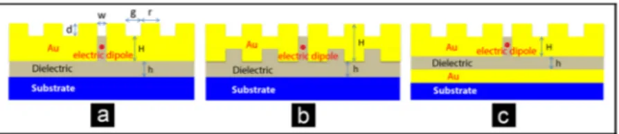
A general scheme of a conventional plasmonic antenna to efficiently collect the emitted light from point sources (NV centers) is shown in Fig. 1(a). We also have presented schematic of a double-side corrugated structure in Fig. 1(b). These two structures are reference samples to assess the performance of metal sub-plated Bulls-eye antenna. Cross-section of the proposed structure including metal sub-plate is demonstrated in Fig. 1(c). All three antennas include a central cavity and co-centered corrugations. Considering the active material including diamond NV centers placed inside the central cavity, geometry of the cavity disciplines the resonance mode of the plasmonic structure and also emission intensity of the active centers. For the emitted light from the NV centers the corrugations will mediate collected light out-coupling quality from the cavity into far-field region. Presented antenna provides several degree of the freedom in design such as cavity width and depth, and corrugations number as well as their radius and etch depth. An ideal structure collects the maximum of the emitted light in a desired wavelength and out-couples it efficiently.
Fig. 1. Schematic cross-section view of (a) conventional, (b) double-side corrugated, and (c) metal sub-plated Bulls-eye antenna. Letters on schemes present antenna parameters as following: w: cavity width, g: groove width, r: ridge width, d: ridge height, H: Antenna Au layer thickness, h: dielectric layer thickness.
Starting from a conventional Bulls-eye structure, optimization has been done through several parametric studies for cavity and corrugation geometrical parameters. In all simulations of the current study, the diamond NV center is modeled as an oscillating electric dipole in plane of the nano-antenna positioned at the center of the 2D structure. Our investigations show that for such position of the modeled NV center the highest coupling and emission efficiencies are achievable [19, 26].
We assume that this emission is degenerated in line with the azimuthal symmetry of the antenna. Validity of such a trend has been verified by experimental data in previous studies
[26]. However, for convenience we consider the XZ-plane view of the Bulls-eye plasmonic antenna. Dependency of the out-coupled intensity on the position of the dipole in central cavity is widely investigated in past researches [19, 26]. For an active center placed inside the central cavity the far-field emission is mainly due to coupling of a dipole emitter parallel to the antenna plate, and therefore we have optimized the antenna for this polarization of the emitting dipole. In our simulations, we have considered the dielectric layer to be PMMA with refractive index of 1.478. It is a common host dielectric for nano-diamond particles with NV centers, and it is compatible with fabrication processes.
Geometrical parameters of an optimized conventional Bulls-eye comprising eight grooves around the central cavity are obtained as: 140 nm diameter of the central cavity (w), 175 nm width of the groove (g), 310 nm width of the ridges (r), 60 nm height of the ridges (d), and 180 nm height of the antenna plate (H). Groove and ridge widths play the main role in defining the plasmonic resonances and plasmon-photon coupling process. These quantities are defined by considering the emission window of diamond NV centers [13, 28] and nature of the surface plasmon polaritons (SPPs) resonances as well as fabrication feasibility of the structure.
We also studied double-side corrugated configurations by introducing symmetric corrugation to down side of the conventional Bulls-eye antenna. Geometrical parameters for this configuration are alike the conventional nano-antenna. Results related to these two configurations are summarized in Fig. 2. We have plotted directivity and normalized intensity spectrum detected around 5 μm over the antenna plate. As it is presented in Fig. 2(a), both antennas have similar directivity magnitude of 7.8 at maximum of the fluorescence spectrum of diamond NV centers. Hereafter, we will consider the optimized conventional Bulls-eye structure as the main reference sample. It has directivity higher than 6 in spectrum of our interest (625 nm – 680 nm) for collection cone of θcone = 4◦ which corresponds to a very narrow directive beam in comparison with the former reports. H. Aouani et.al [9] have reported a high directivity of 9.2 for an optimized antenna with very similar configuration. However, their reported directivity is for collection cone of 22◦. Generally, a high directivity
is favorable for smaller collection angles.
To introduce an optimized double-corrugated configuration one should notice that the directivity behavior of the antenna in one side is not affected by the geometry of the other side [21, 22]. Directionality behavior in each side (top and bottom) is controlled by its corrugation. For the double-corrugated Bulls-eye configuration presented here two sides have different refractive indices, in which the top side medium is air, while the bottom side medium is PMMA. Here for identical corrugations of both sides we expect different plasmon-photon coupling, because SPPs dispersion for each side is dependent on refractive index of the dielectric of that side. In our proposed structure, we are interested in detecting out-coupled intensity in top side. Although the corrugation in bottom side does not affect the directivity, it has considerable effect on magnitude of detected intensity in top side (Fig. 2(b)). In fact, down side corrugation of double-side structure boosts photon collection efficiency for some specific spectrum (modal behavior). This is presented in Fig. 2(b) where field intensity for double-side corrugated antenna is almost twice of that for a conventional structure, around the wavelength of 665 nm. Note that this boost in intensity only happens for an almost narrow spectrum. Physically, in conventional Bulls-eye antenna the bottom-side includes a simple metal-dielectric interface which supports higher number of SPP modes in comparison with the case of a corrugated interface. Therefore, a conventional optimized antenna provides a wide band plasmon-photon coupling.
Fig. 2. (a) Directivity, and (b) Normalized detected intensity over the plate of the structure for of the optimized conventional and double-side corrugated plasmonic Bulls-eye antennas. 2.2 Metal sub-plated bulls-eye antenna
2.2.1 Design and optimization procedure of the antenna
When a point source is placed inside the cavity, a portion of the emitted light is propagated towards antenna substrate. In literature, there are some designs for double-side corrugated antennas in order to efficiently couple photon to plasmon in both sides [21–23]. As we showed this approach leads to a modal narrowband enhancement in far-field intensity. However, here we focus on a wideband directive behavior matching fluorescence spectrum of diamond NV centers. In addition, we seek for a less challenging design from fabrication perspective. Here, we devise to use an additional metal sub-plate which is easier to fabricate in order to collect a portion of the down-scattered light. The schematic of the device was presented above in Fig. 1(c).
For corrugated part of the device we use the optimized geometrical parameters presented in previous section. Then, a parametric study on the thickness of the sandwiched dielectric layer was done. We should note that the sub-plate metal is considered as a thick layer, and the dipole emitter is placed into the central cavity region for better out-coupling intensity performance [29]. To optimize the presented structure, we assume the Au sub-plate to be expanded to infinity into substrate direction. A parametric study has been done to define the optimum thickness of the sandwiched passive dielectric layer by changing its thickness from 40 nm to 200 nm.
Figure 3(a) shows that directivity of the antenna is not sensitive to the thickness of underlying dielectric layer and takes the maximum value of 7.8 for λ = 655 nm. In addition, as it is expected, the presence of the metal sub-plate doesn’t affect the directivity of the structure with respect to conventional and double-side corrugated structures (see Fig. 2(a)). Physically, it is the corrugation configuration, which defines the efficiency of the collimation. Therefore, for structures with the equal corrugation configurations, almost the same directivity values are expected. We should note that according to definition of the directivity (Eq. (1), for samples with different dielectric thicknesses and field intensities we may obtain equal directivities. Therefore, to have a bright source we seek for a case with maximum of the plasmon to photon coupling efficiency and out-coupled intensity. To do this, the related field intensity is calculated and shown in Fig. 3(b). We have two island regions with high values of the intensity, in which the maximum happens for ZPL emission of the diamond NV center. Beside the enhanced emission of NV center based on Purcell effect, a portion of the emitted energy will be out of access because of the resistive loss channels. In Fig. 3(c) and Fig. 3(d), respectively, we have plotted spectrum of Purcell factor and normalized resistive loss density for different thickness of the dielectric layer. To obtain high level of out-coupled light intensity, the tradeoff between the Purcell factor and the resistive loss density should be considered. Accordingly, structures with dielectric thickness of 150-180 nm are the optimum configurations.
Fig. 3. Parametric study to optimize the dielectric layer thickness of metal sub-plated Bulls-eye antenna. Spectrum of (a) Directivity, (b) Normalized field intensity, (c) Purcell factor, and (d) Normalized resistive loss density for various values of dielectric layer thicknesses sandwiched between metal sub-plate and antenna metallic substrate.
2.2.2 Dielectric layer thickness effect
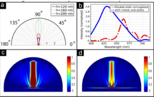
Normalized far-field distributions for wavelength of 637 nm for structures with dielectric thicknesses (h) of 120 nm, 160 nm and 200 nm are plotted in Fig. 4(a). The results are normalized to far-field intensity maximum of a conventional design. Interestingly, the configuration with dielectric thickness of 160 nm emits 3.3 times higher far-field intensity as compared to the conventional configuration. We have plotted the field spectrum for the optimum case of dielectric thickness (h = 160 nm) along with that of double-side corrugated structure in Fig. 4(b). These results reveal a broadband intensity enhancement for the proposed structure with optimum dielectric thickness. Purposefully, the observed maximum intensity of the antenna matches with ZPL emission of NV center.
On the other hand, the intensity level for the structure with h = 160 nm is almost twice of the one with h = 200 nm. Note that the only difference between these two samples is the thickness of the dielectric, thus, the observed difference in far-field intensities would not be only attributed to reflection from metal sub-plate. To investigate this, we have plotted normalized field distributions of these selected configurations in Fig. 4(c) and Fig. 4(d). As it is apparent, there is a brighter pattern for the sample with dielectric thickness of 160 nm. Another point is the localization of intensity around central cavity for the structure with h = 160 nm. While for the structure with h = 200 nm considerable portion of intensity is distributed in dielectric region which is away from central cavity.
Fig. 4. (a) Normalized far-field intensity pattern for samples with dielectric thickness of 120 nm, 160 nm, and 200 nm at the ZPL of NV centers. (b) Normalized field intensity of structure with metal sub-plate (h = 160 nm) compared to that of double-corrugate structures. Normalizations are done based on far-field intensity of the conventional structure. Normalized intensity distribution for a sample with dielectric thickness of (c) 160 nm, and d) 200 nm.
The metal sub-plated Bulls-eye antenna leads to a stronger enhancement of the field and far-field light intensities as compared to both conventional and double-side grating structures. This can be explained mainly due to two phenomena. First, the metal sub-plate reflects back efficiently a portion of down-coupled light towards the cavity. Second, in the case of properly selected width for the sandwiched dielectric layer, strong localization of electromagnetic field can occur in dielectric region. These modes finally could couple to the cavity modes and participate in enhancing the out-coupled light intensity. The concept of plasmon-photon coupling and propagation in metal-dielectric-metal (MDM) recently has been investigated in detail in context of plasmonic patch antennas [26].
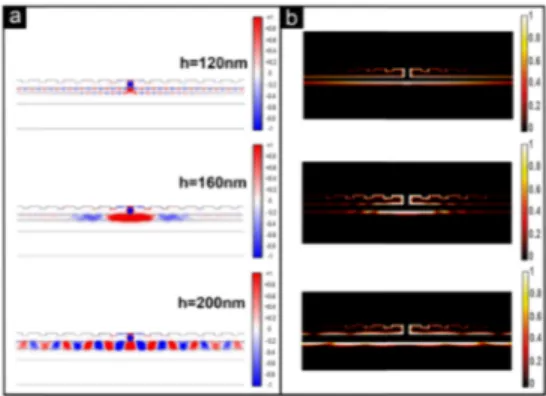
The radial component which play the main role in photon-plasmon coupling is presented in Fig. 5(a) for h = 120 nm, 160 nm, and 200 nm. For the case of h = 160 nm, the electric field is localized around the central cavity, and thus provides more photons to out-couple to the far-field. While for both cases of h = 120 nm and 200 nm the modes are propagating away from the central cavity area, resulting in considerable dissipation of the emitted power through SPPs and down-coupled photons. Note that for the case of h = 120 nm the field is propagating in metal-dielectric interfaces, while for the case of h = 200 nm the MDM waveguide mode propagates in the dielectric region sandwiched between two metal layers [30]. The detailed aspects of this behavior could be clarified through power flow and current density vectors which are presented in Appendix A as Fig. 11. The related normalized resistive losses densities for the mentioned structures are plotted in Fig. 5(b). It is evident from these figures that h = 160 nm provides lower resistive loss density with respect to both cases of h = 120 nm and 200 nm.
Fig. 5. (a) Normalized radial field component for metal sub-plate antennas with dielectric thickness of 120 nm, 160 nm, and 200 nm at the ZPL of NV centers, and (b) Normalized resistive loss distribution for the mentioned samples.
2.3 Bulls-eye antenna with asymmetric configuration
It is possible to steer the collected light from diamond NV centers using properly designed asymmetric corrugations around a central cavity including the NV centers. For a symmetric configuration, light is directed toward far-field region on axis of the antenna. Using the physics behind the directional beaming and theory of the plasmonic gratings we could introduce a configuration for off-axis beaming of the emitted light [9, 20, 31, 32]. For the symmetric case, wave vector of the emitted beam does not have a radial component. By introducing a wave vector in radial direction of out-coupled light the emitted beam from the antenna will obtain an off-axis angle.
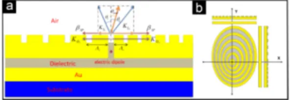
As a general trend, we consider the Bulls-eye plasmonic antenna plate on XY plane with the central cavity placed on the center of the coordination. Thus, the Z axis is the main axis of the structure which the off-axis beaming angle is quantified with respect to this axis. It is possible to introduce asymmetry by choosing whether asymmetric ridges or grooves. A configuration with both asymmetric ridges and grooves is also possible. Cross-sectional and
top views schematic of such a typical asymmetric Bulls-eye antenna are presented in Fig. 6(a) and Fig. 6(b), respectively.
In Fig. 6(a), we divide the scheme to two sides, left and right, and we use indices (r, l) in our notation to define parameters of the each side. The goal is to design an asymmetric structure for steering out-coupled light by off-axis angle of θtotal. For an asymmetric configuration, in any plane vertical to the Bulls-eye structure and encompassing the center of cavity two gratings (left and right sides) can be distinguished. For each side the propagating surface plasmons wave number is perturbed into a directive leaky-wave (out-coupled) by the corrugation. The general phase matching condition for a scattered beam by angle θr, l with respect to the axis of each side can be introduced as [31]
, ( 0sin , ) 2 ,
r l βSP K θr l π
Λ + = (2)
where Λr,l is corrugation period for each side, and βSP = (2π/λ) [(εM εD) / (εM + εD)]1/2 is surface plasmons wave number which is equal for both sides. Here εM and εD stand for electric permittivity of Au and air, respectively. According to Fig. 6(a) and Eq. (2) a generalized phase matching condition for an asymmetric Bulls-eye configuration can be written as
||total ||r ||l .
K = K −K (3)
From this equation we can infer that
0sin total Gr Gl .
K θ = K −K (4)
Therefore, the steering angle is defined by difference between right and left side corrugation wavenumbers.
Fig. 6. (a) Cross-sectional scheme for an asymmetric plasmonic Bulls-eye antenna; related wave numbers for the left and the right side gratings are coupled to each other through the central cavity. (b) Top view of a typical asymmetric Bulls-eye antenna.
2.3.1 Beam steering with asymmetric corrugation ridge
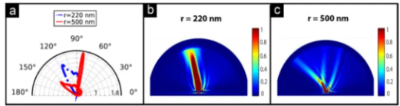
Here, we investigate a structure with asymmetric ridges based on a symmetric metal sub-plated plasmonic antenna, optimized for light collection from diamond NV centers. The aim is to steer efficiently the emitted light at the ZPL wavelength of NV centers. For a conventional symmetric configuration we could consider the ridges as co-centered uniform circular rings. However, when we apply the ridge asymmetry, the width uniformity of the rings is perturbed. To perform this study, various asymmetric structures with fixed groove size of g = 175 nm are considered. In all of them, the width of one side grating ridge is considered as r = 310 nm, while the width of the other side grating ridge is swept from 150 nm to 500 nm. Our results show that for the cases with r = 220 nm and r = 500 nm considerable off-axis beaming is approachable. For r = 220 nm there is a wide directed beam at θ = 29◦, while for r = 500 nm there are two main steered far-field lobes, a narrow lobe at θ
= 10◦ and a wide lobe at θ = 50◦. The related far-field intensity patterns are plotted in Fig.
7(a), and field intensity distributions including the near-field for each case are plotted in Fig. 7(b) and Fig. 7(c). Results are presented for λ = 637 nm, and they are normalized with respect to near-field intensity of the symmetric conventional structure.
Interestingly, the far-field intensity for the asymmetric configuration with metal sub-plate is higher than that of a conventional symmetric structure, without perturbing directivity.
Results related to parametric study on ridge size for Bulls-eye with metal sub-plate and a symmetric conventional optimized one are presented in Part 1 of Appendix B, Fig. 12(a) and Fig. 12(b).
Fig. 7. (a) Normalized far-field intensity distributions for Bulls-eye plasmonic antenna with ridge width asymmetry. Groove width is g = 175 nm, but ridge width is considered as r = 310 nm in one side, while r = 220 nm/500 nm for the other side. Normalized intensity including near-field distribution of the structures with ridge width asymmetry of (b) r = 220 nm, and (c)
r = 500 nm.
2.3.2 Beam steering with asymmetric grooves
Here, we investigate the other possibility to steer the radiated light from the Bulls-eye antenna by introducing asymmetry to grooves. In this case, widths of the ridges are constant, while the corresponding rings are not co-centered anymore (see the general scheme for asymmetric Bulls-eye antenna in Fig. 6(b)). In order to create such configurations, the ridges size are fixed at r = 310 nm. However, the groove size in one side of the grating is kept as g = 175 nm while it is varied from g = 100 nm to 420 on the other side of the grating.
We note that off-axis beaming angle saturates around θ = 15◦ for g = 450 nm and the
related far-field intensity drops to that of a conventional symmetric Bulls-eye antenna (Appendix B, Fig. 13(b)). In Fig. 8(a), we have presented far-field intensity distributions for g = 340 nm and g = 420 nm. For these cases off-axis angles are near to saturation while they retain higher far-field intensities in comparison with conventional structure. For g = 420 nm off-axis angle is θ = 14◦, and the far-field intensity is almost two folds of that of a
conventional device. It is desirable not to lose out-coupled intensity in cost of increasing steering angle.
The related normalized near-field intensity distributions at 637 nm are plotted in Fig. 8(b) and Fig. 8(c). Plots are normalized with respect to the maximum near-field intensity of the symmetric configuration. According to the presented results, the direction of far-field lobs is not consistent with field intensity distribution in vicinity of antenna cavity. The far-field distribution originates from the multiple interferences of diffracted beams with different orders of the asymmetric gratings. This results in a steered far-field distribution as shown in polar graphs. Nevertheless, for near-field distributions a specific phase relation between the out-coupled modes of gratings cannot be defined. In this region, the intensity distribution mainly is disciplined by geometry of asymmetric corrugations. Accordingly, it is not obligatory to have similar near-field and far-field distributions.
Related parametric study results are presented in part 2 of Appendix B (Fig. 13(a) and Fig. 13(b)). According to investigated configurations beam steering is more dependent on ridge asymmetry rather than groove asymmetry. However, for the case of asymmetric grooves the steered beam remains almost narrow.
Fig. 8. (a) Normalized far-field intensity distributions for Bulls-eye plasmonic antenna with groove width asymmetry. Ridge width is r = 310 nm, but groove width is considered as g = 175 nm in one side, while g = 340 nm/420 nm for the other side. Normalized intensity including near-field distribution of the structures with groove width asymmetry of (b) g = 340 nm, and (c) g = 420 nm.
2.3.3 Beam steering with asymmetric grooves and ridges
Based on results of the previous sections, here we apply the asymmetry to both groove and ridge widths. Designs include a metal sub-plate as its constructive effect is proved already. We note that for the asymmetric ridges case beam is steered toward angles larger than θ = 90◦
(on-axis angle) while for the case of asymmetric grooves it steers toward angles smaller than
θ = 90◦. Therefore, we could infer that if we apply both kinds of asymmetries in two different
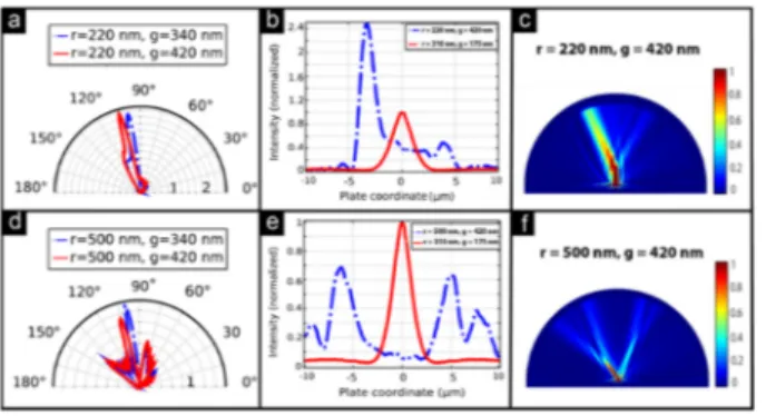
sides of Bulls-eye cross-section, we would reach to higher steering angles. We name such a design as double-asymmetric structure. Thus, for the side with ridge asymmetry we fix groove width at g = 175 nm, while for the other side with groove asymmetry we fix the ridge size at r = 310 nm. Based on the discussed results in the previous sections, here, we have studied four different double asymmetric structures. Normalized far-field intensities, near-field intensity distributions, and detected intensity in near-field for these double asymmetric devices are presented in Fig. 9. Figures are plotted for ZPL emission of the diamond NV center and are normalized with respect to intensity of the conventional optimized device. The discussed case corresponds to a Bulls-eye antenna in XY plane including elliptical non-uniform rings.
Figures are divided into two groups: single-lobe steering and double-lobe steering. These regimes are disciplined by ridge asymmetry. For r = 220 nm which is smaller than the optimal ridge width (r = 310 nm) single-lobe regime appears (Fig. 9(a)), while for r = 500 nm double-lobe regime dominates (Fig. 9(d)). For r = 220 nm and g = 420 nm a narrow-width beam with off-axis angle θ = 15◦ is accessible. For single-lobe narrow width cases far-field intensities are
two times higher than that of the conventional device, which are very promising for bright off-axial beaming. In Fig. 9(b) we have plotted field intensity pattern over the semicircular boundary with radius of ~6 μm above antenna platform. These results are important for sensing, microscopy, and beam shaping. A proper horizontal shift about 3.5 μm is apparent when comparing with symmetric conventional case which is also presented in the same figure (red solid line). In Fig. 9(c) the normalized near-field intensity distribution for r = 220 nm and
Fig. 9. Normalized single-lobe (a) far-field intensity distributions for the cases of r = 220 nm and g = 340 nm (blue dot dashed)/420 nm (red solid), (b) field intensity for the cases of r = 220 nm and g = 420 nm (blue dot-dashed line) and symmetric structure (red solid). Normalized double-lobe, (c) near-field intensity distribution for the case of r = 220 nm and g = 420 nm, (d) far-field intensity distributions for the cases of r = 500 nm and g = 340 nm (blue dot dashed)/420 nm (red solid), (e) field intensity for the cases of r = 500 nm and g = 420 nm (blue dot-dashed) and symmetric structure (red solid), (f) near-field intensity distribution for the cases of r = 500 nm and g = 420 nm.
On the other hand, for r = 500 nm and g = 420 nm we have two main lobes with intensity peaks in θ = −10◦, 15◦, 50◦ (Fig. 9(d)). Promisingly, for these cases the steered beam retains
acceptable level of intensity. For instance, far-field intensity peak on θ = 50◦ is dropped only
about 20% in comparison with conventional device. In addition, double-lobe regime seems to be interesting in sense of deflecting emitted energy away from the axis by separating it into two parts. This fact is apparent in Fig. 9(e); which is for detected intensities in few micrometers away from device plate. Two separated intensity peaks are well-placed from each other by about 11 μm. Similar behavior is observed for the case of r = 500 nm and g = 340 nm. The normalized near-field intensity distribution for the case of r = 500 nm and g = 420 nm is presented in Fig. 9(f).
2.3.4 Three-dimensional Out-Coupled Beam Representation
Geometrical symmetries play the main role in defining the off-axis beaming angle. Aforementioned designs were presented in cross-sectional view, and the cross-section plane was a unique plane which crosses the Bulls-eye structure in particular ridge and groove widths. For all of those structures the plasmonic Bulls-eye antenna is symmetric with respect to the asymmetric cross-section plane (see the scheme in Fig. 10(a)). By applying asymmetry on X or Y direction the beam is steered on XZ or YZ plane, respectively. It is desirable to steer the directed beam inside a cone with an apex angle θ. This aim is approachable by displacing non-uniform elliptical rings around the central cavity. As a general scheme, Fig. 6(b) presents a design with asymmetry on both X and Y directions. Based on this scheme, we can define several configurations for spatial beam steering, according to rings widths as well as their displacement magnitude and direction. One interesting case is the equal displacement of the rings in X and Y directions. Such a case is equivalent to an asymmetric configuration with asymmetry on one axis in a rotated frame. As a complex design, one could take advantage of asymmetries for both ridge and groove widths on both planes. In order to prove the concept we have considered two particular cases: First, a structure with asymmetry on X-axis, and second, a structure with equal asymmetries in X and Y-axis. For each of these cases one would use ridge asymmetry as well as groove asymmetry.
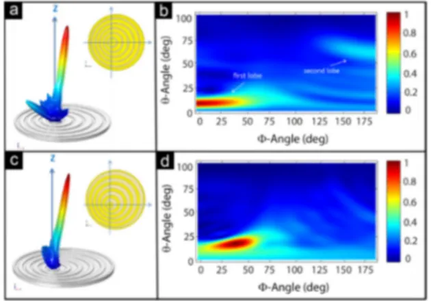
In first configuration, we have applied ridge asymmetry in X direction, and XZ plane is the main asymmetry plane (inset of Fig. 10(a)). Ridge width varies from r = 310 nm to 500 nm while the groove size is fixed on g = 175 nm. Far-field intensity distribution for this structure is shown in Fig. 10(a), presenting beam steering along X-axis. In addition, two main far-field lobes which are characteristic of a structure with ridge asymmetry are evident. To
define precisely the magnitude of the steering angle we have plotted counter map of the far-field versus polar angles θ and φ in Fig. 10(b). Here, we define angle θ as the beam angle from Z-axis (θ = 0 for the symmetric structure) and angle φ is azimuthal in XY plane, based on spherical coordination. Maximum of the first lobe is steered about 7° with respect to the Z axis while the second wider lobe is directed around 55°. Azimuthal angle for first and second lobe are near to 0 and 180 degrees, which shows that the steered beam mainly is concentrated on X-axis. Directivity for the main lobe is calculated as 11.5 for θ = 7° and φ = 0°.
The second configuration (inset of Fig. 10(b)) has two main asymmetry planes of XZ and YZ, in which we have applied groove asymmetry for both X and Y directions. Groove width varies from g = 175 nm to 420 nm while the ridge width is fixed on r = 310 nm. Three dimensional far-field intensity for this configuration is presented in Fig. 10(c). Considering that the groove asymmetry is applied in two main asymmetry planes, we obtain out of X and Y-axis beaming with single lobe performance. Such a performance provides a narrow-width far-field pattern. In Fig. 10(d) counter map of the far-field versus polar angles reveals the precise amount of the steering angle. Directivity of 16 is approachable for θ = 15° and φ = 46°.
Note that cylindrical coordination of the structure helps to sweep the steering angle over a cone with apex angle of θ, which is equivalent to turning the antenna plate around the Z-axis. Furthermore, either smaller or larger angles with different directivities are approachable with other possible compositions of ridge and groove asymmetries as well as elliptical rings orientations.
Fig. 10. (a) 3D and (b) Counter map far-field intensity distribution for a Bulls-eye plasmonic antenna including one main asymmetry plane with ridge asymmetry, (c) 3D and (d) counter map far-field intensity distribution for a Bulls-eye plasmonic antenna including two main asymmetry planes with groove asymmetry. The presented insets in (a) and (c) parts are top views of the mentioned cases. Far-fields are calculated over a sphere with 1 m radius surrounding the plasmonic Bulls-eye antenna for ZPL emission of the diamond NV center.
3. Conclusion
In this work, we have introduced a plasmonic Bulls-eye antenna to efficiently collect light from diamond NV centers and steer it over a spatial off-axis angle. In order to improve the efficiency of the out-coupled light intensity we have added a metal sub-plate underneath the conventional Bulls-eye metallic plate. The presence of a metal sub-plate increases the far-field intensity considerably without deviating directivity of the antenna. Moreover, the antenna with metal sub-plate reveals remarkable enhancement of the out-coupled field intensity in comparison with that of the optimized conventional antenna, without disturbing the structure directivity. In addition, for such a structure we have investigated different approaches for off-axial steering of the directive beam. Three trends based on ridge, groove, and both ridge and groove asymmetries were discussed, which provide several degrees of
freedom in designing a Bulls-eye nano-antenna for off-axial beam steering. Finally, we showed that a full-asymmetric structure can steer the collected light from diamond NV centers over a cone. Based on our results both single and double-lobe regimes are achievable.
According to currently well-developed process flow for the fabrication of plasmonic corrugation, our design could pave the way for much efficient light extraction from diamond NV centers and also quantum dots, as it is the major challenge towards practical applications. This design is fully compatible with standard nanofabrication processes, and as a main advantage adding such a simple metal sub-plate beneath the conventional Bulls-eye antenna does not require additional nanolithography steps. Our designed antenna could have potential applications for low-loss near field power coupling and division, which is important from the perspective of sensing, microscopy, and beam shaping. Additionally, the remarkable efficiency of this antenna in broadband collection of photons from quantum emitters is paramount in emerging quantum networks applications.
Appendix A - The influence of the dielectric layer thickness on power dissipation
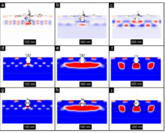
In section 2-2 of the main text, through Fig. 5 we show that a plasmonic Bulls-eye antenna with a metal sub-plate could operate in different regimes. These regimes could be characterized by thickness of the sandwiched dielectric layer between two metallic plates of the structure. Here, in Fig. 11 we have presented data for three different structures with h = 120 nm, h = 160 nm, and h = 200 nm representing different operating regimes.
Starting from the case of h = 120 nm, Fig. 11(a) demonstrates a periodic behavior of electric field vectors along two interfaces. Such a behavior is due to the propagating of SPPs through two metal-dielectric interfaces. This propagation is demonstrated through the power flow vectors in Fig. 11(d), showing that the power flows get away from the central cavity region. In Fig. 11(g) we could realize current density along two metal-dielectric interfaces which proves the nature of the propagation modes lay on SPPs.
For the case of h = 160 nm, electric field vectors in Fig. 11(b) are aligned almost in one direction in metal-dielectric interface which could be a demonstrative of a localized field. Fig. 11(e) shows that for this case the out-coupling power flow is dominant. In such a situation we expect the minimum amount of photon-plasmon coupling in region far away from the central cavity. This fact is demonstrated through Fig. 11(h) in which the current density decreases abruptly in metal-dielectric interfaces by getting away from the cavity region.
Fig. 11. (a), (b), (c) Magnetic field counter map (white and black colors representing maximum and minimum, respectively), and electric field vectors in red, and (d), (e), (f) Counter map of radial component of the electric field (red and blue colors representing maximum and minimum, respectively) and power flow vectors in black, and (g), (h), (i) Counter map of radial component of the electric field (red and blue colors representing maximum and minimum, respectively) and current density vectors in black. These figures are plotted for three structures with dielectric layer thicknesses of h = 120 nm, 160 nm, 200 nm.
Finally, for the case of h = 200 nm, in Fig. 11(c) demonstrates the repeating behavior of surface plasmon propagation through electric field along the metal-dielectric interfaces. For this case the most of the emitted power is coupled to the antennas down space, as presented through power flow vectors in Fig. 11(f). A small portion of this light is coupled to surface plasmons in metal-dielectric interfaces, while the considerable rest is guided as propagating photons through the dielectric waveguide between two metal walls. Note that, in this case also SPPs play an important role in directing away the electromagnetic energy from the central cavity region. This fact could be realized by noting to the size and direction of the current density vectors in Fig. 11(i).
Appendix B - Parametric studies for asymmetric structures
In section 2.3 of the main text, we proposed the trends to steer the emitted light from the plasmonic Bulls-eye antenna with metallic sub-plate. Here, we present the parametric study procedure to define the most proper ridge and groove widths for beam steering.
Part 1) Asymmetric corrugation ridge
To perform this study, various asymmetric structures with fixed groove size of g = 175 nm are considered. In all of them, the width of one side grating ridge is considered as r = 310 nm, while the width of the other side grating ridge is swept from 150 nm to 500 nm. Note that all of these structures include a dielectric layer with thickness of h = 165 nm which is sandwiched between metallic sub-plate and antenna main plate.
The far-field intensity pattern and the out-coupled light intensity detected on a semicircle (with radius of ~ 6 μm and on top of the antenna) are shown in Fig. 12(a) and Fig. 12(b), respectively. The graphs are normalized to the corresponding values of the conventional design.
Fig. 12. Parametric study on ridge width of the asymmetric metal sub-plated Bulls-eye antenna including normalized (a) far-field pattern, and (b) out-coupled light intensity.
Part 2) Asymmetric corrugation groove
For this study, the ridges size are fixed at r = 310 nm, while the groove size on one side of the grating is kept as g = 175 nm and it is varied from g = 100 nm to 420 nm on the other side of the grating. Likewise previous part, the studied structures include a metal sub-plate and a sandwiched dielectric layer with thickness of h = 165 nm.
The far-field intensity pattern and the out-coupled light intensity detected on a semicircle (with radius of ~ 6 μm on top of the antenna) are shown in Fig. 13(a) and Fig. 13(b), respectively. The graphs are normalized to the corresponding values of the conventional design.
Fig. 13. Parametric study on groove width of the metal sub-plated asymmetric Bulls-eye antenna including normalized (a) far-field pattern, and (b) out-coupled light intensity.
Funding
DPT-HAMIT, funded by Academy of Finland (301820).
Acknowledgments
E.O. acknowledges the partial support from the Turkish Academy of Sciences. H.C. acknowledges support from the Science Academy of Turkey through the BAGEP programme.