Generation of 2‑𝜇 J 410‑fs pulses from a single‑mode chirped‑pulse
fiber laser operating at 1550 nm
Svitlana Pavlova1 · Hossein Rezaei2 · Ihor Pavlov2 · Hamit Kalaycıoğlu2 · Fatih Ömer Ilday2,3,4
Received: 16 May 2018 / Accepted: 9 September 2018 / Published online: 19 September 2018 © Springer-Verlag GmbH Germany, part of Springer Nature 2018
Abstract
We report on a simple, robust, femtosecond chirped-pulse-amplification system, based on Er- and Er-Yb-doped fibers, oper-ating at a central wavelength of 1555 nm. The entire system is constructed from commercially available fiber components, except the grating compressor, for easy duplication by other researchers. The laser system produces chirped pulses with up to 4 𝜇J of pulse energy at 250 kHz. After dechirping, the pulse duration is 410 fs and the pulse energy is reduced to 2 𝜇J . The repetition rate of the laser is electronically tunable between 125 kHz and 60 MHz, limited by strong amplified spontaneous emission (ASE) generation at the low end. The amplifier system is almost completely fiber integrated, except for the pump delivery into the final amplifier stage, which is free-space backward-pumped to reduce undesired nonlinear effects, and the compressor which was designed using the gratings. The laser is practically free of misalignment and has exhibited excellent long-term stability during its use in various experiments for more than 600 working hours.
1 Introduction
In the past decade, several new applications areas of high-energy and high-power femtosecond laser sources around 1.5 𝜇m central wavelength have been developed. These include, in addition to well-known scientific applications [1], medical surgery [2, 3], industrial micromachining [4], micromachining in transparent materials [5], and most recently, silicon [6–8]. However, development of compact fiber-based laser sources have lagged far behind those in Yb-doped and Tm-doped fiber lasers. Various ultrashort fiber laser systems operating at 1.5 𝜇m with different design have been reported so far. The combination of chirped pulse application (CPA) technique with large-mode-area (LMA) clad pumping fiber technology is a common factor among
them [9]. These reports cover a wide range of pulse energies, durations and repetition rates: A 156-MHz-repetition-rate system with 450 fs pulse duration and average power of 10 W was demonstrated in [10]. In [11], generation of 175-fs pulses at 3.5 W of average power at a repetition rate of 43 MHz was reported. The paper [12] describes a system based on a single-mode EY- fiber, with a maximum average power of 10 W at repetition rates from 600 kHz to 100 MHz and the pulse durations 400–600 fs. Femtosecond pulses with 1.5 𝜇J energy and 605 fs duration at 300 kHz were reported in [13]. In [14], the authors reported on the generation of 2-𝜇J , 880-fs pulses at repetition rates ranging from 100 kHz to 1 MHz. These results were obtained by readily available, splicable fibers producing diffraction-limited outputs. A par-allel development has seen the use of specially designed fib-ers and in-band pumping to reduce the effective nonlinearity by orders of magnitude, and as a result, considerably higher pulse energies have been achieved, albeit at the expense of much more complicated setups. In [15], an Er-fiber laser sys-tem operating at 50 kHz and generating 25 𝜇J pulse energies and a pulse duration of 800 fs was demonstrated. At the high end of the energy scale, a fiber laser system generating 636-fs pulses with pulse energy of 100 𝜇J was reported [16] and a similar system reporting sub-500 fs pulses with 913 𝜇J pulse energy and average output power of 4.4 W was presented in [17]. However, the need for specialty components appear to have limited the impact of these reports, judging by that no
* Fatih Ömer Ilday [email protected]
1 Institute of Physics of the NAS of Ukraine, Kyiv 03028,
Ukraine
2 Department of Physics, Bilkent University, 06800 Ankara,
Turkey
3 Department of Electrical and Electronics Engineering,
Bilkent University, 06800 Ankara, Turkey
4 UNAM, National Nanotechnology Research Center
and Institute of Materials Science and Nanotechnology, Bilkent University, 06800 Ankara, Turkey
other groups appear to have duplicated them. We believe that there continues to be strong demand for simple designs, which can easily be duplicated by researchers without access to specialty components.
Here, we report on a simple CPA system that uses only commercially available fibers and fiber components, achiev-ing 2 𝜇J pulse energy with 410 fs pulse duration. The repeti-tion rate of the system is adjustable from 60 MHz (the rep-etition rate of the seed oscillator) down to 250 kHz, limited by the growing presence of spontaneous emission (ASE) at low repetition rates. The amplifier system is fully fiber inte-grated, except for delivery of pump power to the last ampli-fier, which is free-space backward-pumped in order to avoid excessive nonlinear effects, and the compressor which was designed using the gratings. The presence of this free-space part notwithstanding, the system has demonstrated excellent long-term stability during its use in various experiments in our laboratory over the course of one year, including the work reported in [8].
2 Experiments and results
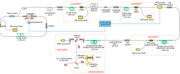
Schematics of the experimental setup is shown in Fig. 1. The laser system consists of a mode-locked seed oscilla-tor, three pre-amplifiers, a main amplifier and a diffraction grating-based dispersive delay line, based on the all-fiber femtosecond fiber laser-amplifier architecture first reported in [18]. We performed numerical simulations of pulse gen-eration and propagation to help understand the influence of nonlinear effects and gain narrowing, to help determine the optimal placement and length of the stretching fibers, as well as to interpret the experimental measurements. The
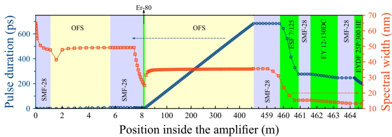
simulations are fairly standard in terms of the included effects and the numerical method, having being used in numerous reports from our group. Further details can be found in [7, 19]. The results of modeling the evolution of spectral width and pulse duration in the amplifier system as described above are shown in Fig. 2.
Next, we describe the experimental setup in detail. The oscillator is passively mode-locked using nonlinear polari-zation evolution. The gain fiber of the oscillator is 1 m of single-mode Er-doped fiber (Er80 4/125, Thorlabs Inc.), which is backward pumped by a standard singl-emode laser diode at 976 nm through a wavelength division multi-plexer (WDM). The rest of the fibers are of standard SMF-28 type. The entire length of the fibers comprising the cavity is approximately 3.6 m, with a corresponding total dispersion of −19700 fs2 . This length estimate is consistent with the measured repetition rate of 56.8 MHz. The aver-age power, extracted from the cavity through a 20 % fiber-coupler was 7.3 mW. Thus, the intra-cavity power and pulse energy were calculated to be 36.5 mW and 0.65 nJ, respectively. The (full-width at half-maximum, FWHM) bandwidth of the oscillator output measured at this port was 40.8 nm (Fig. 3a), centered at 1564.8 nm. The pulses were negatively chirped, but still of sub-picosecond dura-tion. The radio frequency (RF) spectral measurement with 10 GHz scan range and 50 kHz resolution bandwidth, coupled with long-range autocorrelation scans confirmed single-pulsed operation (inset of Fig. 3a). A similar RF measurement for a 1-kHz scan range and 10-Hz resolution bandwidth, centered at the frequency of the fundamental harmonic of the oscillator, exhibited ∼ 70 dB signal-to-noise ratio, which indicates excellent short-term stability.
WDM QWP fiber coupler 20% SM pump diode QWP HWP Er-80-4/125 (100 cm) PBS isolator pre-stretcher (4 m)
isolator stretcher (450 m) polarization controller PM isolator Er-80-4/125 (80 cm) WDM SM pump diode
pre-amplifier 1 pre-amplifier 2 optic modulatorPM
acousto-PM Er-fiber ESF-7/125 (115 cm) PM WDM SM pump diode PM pump-signal combiner MM pump diode mode-matching fiber (20 cm) double-clad Er-fiber PM-EYDF-12/130-HE (165 cm) pre-amplifier 3 double-clad Er-fiber PLMA-EYDF-25P/300-HE (50 cm) main amplifier MM pump diode dichroic mirror mirror mirror diffraction grating pulse gating electronics polarizing isolator PM isolator 2- J, 410-fs pulses at 250 kHz
dispersive delay line diffraction
grating photodetector
Fig. 1 Schematic of Er-Yb femtosecond laser system: QWP quarter waveplate, HWP half waveplate, PBS polarizing beamsplitter, WDM wave-length division multiplexer, SM single-mode, MM multimode, PM polarization maintaining
The pulses extracted from the oscillator’s fiber port are directed into the first pre-amplifier based on 80 cm-long gain fiber (Er80-4/125, Thorlabs, Inc.), which is back-ward-pumped through a WDM (pre-amplifier 1 in Fig. 1). However, in order to reduce nonlinearity during the pre-amplification, a short segment of a normal-dispersion stretch fiber (4 m, D = −44 ps∕nm.km , OFS Ocean fiber) is used before the preamplifier (the pre-stretcher in Fig. 1). While the approximate length of the pre-stretcher to obtain the
broadest spectral width with minimal modulations was esti-mated from numerical simulations, its precise values was determined experimentally, using the cut-back method. In essence, we arrange for the balancing of gain narrowing with self-phase modulation [20] at the output of this pre-amplifier. The measured optical spectra with and without the pre-stretcher are shown in Fig. 3b. The nonlinear phase shifts at the output of the pre-amplifier with and without the pre-stretcher were estimated as 1.3 𝜋 and 2.4 𝜋 , respectively.
0 2 4 6 8 0 200 400 600
Pulse duration (ps
)
100 200 300 400Position inside the amplifier (m)
459 460 461 462 463 464 10 20 30 40 50 60 70
Spectral width (nm
)
SMF-2 8 SMF-2 8 SMF-2 8 SMF-2 8 SMF-2 8 OFS OFS Er-80 ESF 7/125 EY 12-130D C EYDF 25P/300 HEFig. 2 Simulation results for evolution of the pulse duration and spectral width along the amplifier system
Fig. 3 a Measured optical
spec-trum of the oscillator output, where the inset shows the RF spectrum, b measured optical spectra after the first pream-plifier without pre-stretcher (green dashed line) and with pre-stretcher (blue solid line),
c measured optical spectrum of
the final output after dechirping in the dispersive delay line for a pulse energy of 2 𝜇J , and d the measured autocorrelation trace corresponding to the results shown in c. Inset of c shows the spatial profile of the beam
−4 −2 0 2 4 −4 −2 0 2 4 x (mm) y (mm) 1530 1560 1590 1620 1650 0 0.2 0.4 0.6 0.8 1 Wavelength (nm) Power (a.u.) 1500 1530 1560 1590 1620 0 0.2 0.4 0.6 0.8 1 Wavelength (nm)
b
Normalized intensity 1530 1540 1550 1560 1570 1580 0 0.2 0.4 0.6 0.8 1 Wavelength (nm) Power (a.u.) −8 −6 −4 −2 0 2 4 6 8 0 0.2 0.4 0.6 0.8 1 Time delay (ps)Autocorrelation signal (a.u.)
a
d
c
0 5 10 Frequency (GHz) RF signal (a.u.)The optimal output spectrum had a bandwidth of 25.6 nm and is centered at 1557 nm (black solid line in Fig. 3b). The output power after the pre-amplifier was 118 mW, which corresponds to 2 nJ for the pulse energy.
After the first preamplifier, the pulses traverse the main stretcher, which consists of 450 m of the single-mode fiber with D = −44 ps∕(nm.km) . The estimated pulse duration after the stretcher was 520 ps. Since all of the fiber com-ponents and gain fibers after the stretcher are polarization maintaining (PM), we used a polarization controller, fol-lowed by a polarizing isolator (fast axis is blocked). The polarization controller was adjusted to maximize the signal obtained after the isolator, which was 50 mW. The second preamplifier (pre-amplifier 2 in Fig. 1) consists of 1.15 m of PM single-mode Er-doped fiber (ESF - 7/125, Nufern, Inc.) backward-pumped in core by a 976-nm diode through a PM WDM. The signal power after the second preampli-fier was 213 mW (for a pump power of 580 mW). After the second preamplifier an acousto-optic modulator (AOM) is used to decrease the repetition rate of the laser. The AOM is controlled with a homemade electronic card based on a field-programmable gate-array (FPGA), triggered by a photo-detector signal obtained from one of the oscillator outputs. Due to the low duty cycle of pulse picking at low repetition rates and relatively high internal losses of the AOM (3 dB), the signal power after the AOM decreases precipitously. For example, for a repetition rate of 250 kHz, the signal power after the AOM is merely 0.4 mW. For this reason, an addi-tional pre-amplifier is included before coupling into the main amplifier. This pre-amplifier (pre-amplifier 3 in Fig. 1) is made of 165 cm-long PM Er/Yb co-doped double-clad fiber (PM-EYDF-12/130-HE, Nufern, Inc.). It is cladding pumped in the backward direction by multimode diode operating at 976 nm through PM multimode pump combiner. The output power of this pre-amplifier (pre-amplifier 3) at 1 MHz rep-etition rate was 303 mW at a pump power of 2.65 W. Due to gain narrowing, the signal had a bandwidth of 13.6 nm centered at 1543 nm at this power level. This suggests that decreasing the length of the stretch fiber would be the opti-mal way to compensate the gain narrowing in pre-amplifier 2 by spectral broadening due to self-phase modulation. In fact, ideally a dedicated stretcher should be placed preceding each amplifier, i.e., four segments of stretcher fiber in this laser, each of which would be of optimal length for balancing of gain narrowing. However, this would require placement of two other stretchers, approximately matching the length to be removed from the currently 450 m-long stretcher. Unfor-tunately, this was not possible in our work due to lack of any readily available PM fibers with large normal dispersion at 1550 nm, given that pre-amplifier 3 and the main amplifier are built from PM fibers. Nevertheless, a similar experimen-tal optimization was performed on the length of the second stretcher and the minimum achievable pulse duration after
this stage (obtained with an external grating compressor) was 356 fs with a pulse energy of nearly 300 nJ. This result already compares favorably to our recent report in terms of peak power [11], where the pulse was shorter (175 fs), but for a lower pulse energy of 80 nJ.
The main amplifier (main amplifier in Fig. 1) consists of 50 cm-long large mode area PM Er/Yb co-doped fiber (PLMA-EYDF-25P/300-HE, Nufern, Inc.) with a core diam-eter of 25 𝜇m . Before the gain fiber, a piece of 20 cm passive fiber with 20-𝜇m core and 125-𝜇m cladding diameters is placed to act as a simple, but effective mode field adapter. The amplifier is backward pumped by a high-power multi-mode diode at 976 nm through free space. The pump diode output from MM fiber (105/125) is collimated by a 20 mm focal length lens and focused into the 8◦ angle-cleaved facet of the gain fiber by a high-power compatible focusing objec-tive (LMH-10X-1064, Thorlabs, Inc.). The same objecobjec-tive is used for collimating the amplified signal beam from the gain fiber. The signal and pump are separated by a dichroic beam splitter mirror (DMSP1180, Thorlabs, Inc.). After the main amplifier, the output pulses are dechirped with a dispersive delay line, which comprises of a pair of 900 line/mm trans-mission diffraction gratings (WP-900/1550-50.8, Wasatch Photonics, Inc.). The transmission efficiency of the com-pressor was measured to be 65% . The output parameters of the system at different repetition rates are shown in Table 1.
The output spectrum and the autocorrelation trace of the system measured measured during operation at 250 kHz are shown in Figure 3c, d. At this repetition rate, the average power was measured to be 540 mW, which corresponds to 2 𝜇J of pulse energy after taking into account ASE content (see detailed discussion below). The measured pulse dura-tion is inferred to be 410 fs based on the autocorreladura-tion measurements, assuming a deconvolution factor correspond-ing to a Gaussian pulse shape. The inset of Fig. 3c shows the spatial profile of the output beam, which is nearly Gaussian. The beam quality was measured, yielding M2 = 1.4.
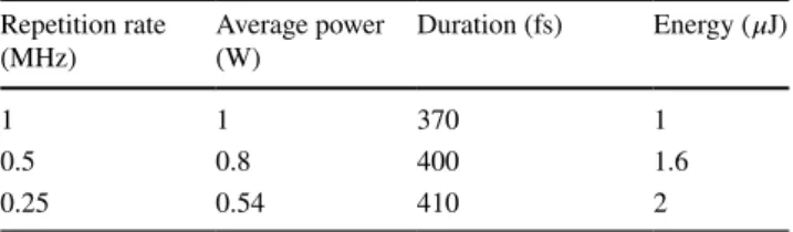
We have intentionally kept the the gain fiber of the final amplifier short to reduce the accumulated nonlinear phase shift. A consequence of this decision is the reduction of the efficiency of the amplifier to ∼ 15% , whereas an opti-mal length would achieve an efficiency as high as ∼ 45% . Although we did not observe saturation of the output power Table 1 Parameters of the dechirped pulses produced by the laser system at different repetition rates
Repetition rate
(MHz) Average power (W) Duration (fs) Energy ( 𝜇J)
1 1 370 1
0.5 0.8 400 1.6
with increasing the pump power, the low efficiency of the amplifier indirectly imposes limitations to the achievable average power in our case. The first mechanism is due to the significant amount of unabsorbed pump light after the gain fiber, which thermally damages the coating of the mode-matching passive fiber placed before the gain fiber beyond a certain pump power. The second mechanism is the ther-mal damage of the tip of the gain fiber at the output of the system at high pump power. Both of these limitations can be overcome by introducing a commercial-grade cladding-mode stripper before the gain fiber and by introducing an end-cap comprised of a piece of coreless fiber at the output end. However, it is these limitations that presently limit the average powers for safe, long-term operation. Additionally, the collimating objective in our system was B coated, with nearly 30% loss at 1.5 𝜇m . Replacing the objective with proper coating would immediately increase the output pulse energy by 30% , to 2.6 𝜇J , without any changes in the pulse duration.
Given the present limitations to average power, the ulti-mate limitation for pulse energy arises from the limit to reducing the repetition rate. This value, itself, is limited by the onset of significant ASE generation between the pulses. It is important to note that presence of large amounts of ASE can easily be overlooked and we strongly suspect that it has accompanied several of the high-energy results reported in the literature. In our case, we carefully measured the ASE content with a setup similar to those described in [21–23].
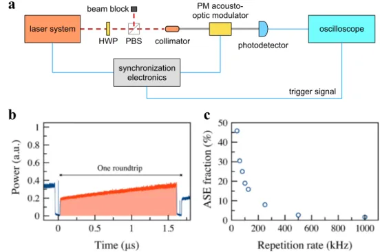
The schematic of the ASE measurement setup is shown in Fig. 4a. A small portion of the output light (20 mW) is cou-pled into a single-mode fiber and passed through a second AOM. The second AOM is triggered with the complement of the signal for the AOM in of the system, such that when the latter is high (transmitting) the former is low (blocking), which allows us to block the laser pulses, and pass only the temporal region between them, where the ASE content resides. Thus, we are able to directly and accurately measure the ASE power, even when it is a small fraction of the laser output. Fig. 4b shows the oscilloscope trace of the electri-cal signal taken from the photo-detector when the pulses are blocked by the second AOM, where the shaded region indicates the ASE generation between the temporal gates applied by the AOM. By measuring the ratio of the energy within this region to the energy within an entire roundtrip when the AOM is set to pass all signal, we obtain the frac-tion of ASE within the output signal. We note that since the suppression ratio of the AOM is limited to 50 dB, a small portion of the blocked pulses leak through and are visible under high magnification on the oscilloscope. However, their integrated contribution is negligible. The measured ASE ratios for different repetition rates are shown in Fig. 4c. The minimum ASE amount was measured at 1 MHz ( 1.64 % ), and it increases sharply when the system is operating at a repetition rate below 100 kHz, reaching 45% at 40 kHz. At 250 kHz, it was 8% . Therefore, we decided to limit operation to 250 kHz, while noting that this is not a hard limit.
Fig. 4 a Schematics of the ASE
measurement setup: HWP half-waveplate; PBS polarizing beam splitter. b Oscilloscope trace showing the buildup dynamics of ASE (shaded region) for 600 kHz repetition rate. c Fraction of ASE as a function of repeti-tion rate laser system HWP PBS PM acousto-optic modulator photodetector synchronization electronics oscilloscope trigger signal beam block collimator
a
b
c
3 Conclusion
We report on a simple, robust, compact and highly inte-grated fiber laser system operating at a central wavelength near 1.5 𝜇m . The repetition rate of the system is adjustable from 60 MHz to down 250 kHz, limited by significant ASE content at low repetition rates. At 250 kHz, the system deliv-ers 2-𝜇J de-chirped pulses with 410-fs duration. However, the pulse energy can easily be increased to 3.4 𝜇J without changing the pulse generation at all, but simply replacing the lossy objective at the output and also replacing the lossy gratings with the typical values routinely obtained at 1 𝜇m [21]. Finally, we would like to note that the operation of the system in the range between 1 MHz to 250 kHz was highly stable over a long period of time (more than 600 working hours over the course of 1 year) without any reduction of the output power or misalignment. It was successfully applied to writing waveguides deep inside Si chips [8], as well as time-resolved pump-probe measurements of filament-induc-ing pulse propagation in Si (manuscript is under prepara-tion). In contrast to many reports on Er-fiber lasers in recent years, the laser reported here is built using only commer-cially available components, the details of which have been provided in this report. Thus, we expect it to be duplicated easily by any researcher, who is interested in using this low-cost, reliable laser source of microjoule-level femtosecond pulses.
Acknowledgements This work was funded by Türkiye Bilimsel ve Teknolojik Arastirma Kurumu (TÜBITAK) (114F256). This work was funded, in part, by the European Research Council (ERC) Consolidator Grant ERC-617521 NLL. The authors acknowledge discussions with Parviz Elahi and Ö. Akcaalan.
References
1. E. Fermann, I. Hartl, Ultrafast fibre lasers. Nat. Photon 7, 868–874 (2013)
2. C. Crotti, F. Deloison, F. Alahyane, F. Aptel, L. Kowalczuk, J.-M. Legeais, D.A. Peyrot, M. Savoldelli, K. Plamann, Wavelength optimization in femtosecond laser corneal surgery. Invest. Oph-thalmol. Vis. Sci. 54, 3340–3349 (2013)
3. K. Plamann, F. Aptel, C. Arnold, A. Courjaud, C. Crotti, F. Deloi-son, F. Druon, P. Georges, M. Hanna, J.-M. Legeais, F. Morin, E. Mottay, V. Nuzzo, D.A. Peyrot, M. Savoldelli, Ultrashort pulse laser surgery of the cornea and the sclera. J. Opt. 12, 084002 (2010)
4. M. Malinauskas, A. Zukauskas, S. Hasegawa, Y. Hayasaki, V. Mizeikis, R. Buividas, S. Juodkazis, Ultrafast laser processing of materials: from science to industry. Light Sci. Appl. 5, e16133 (2016)
5. R. Gattass, E. Mazur, Femtosecond laser micromachining in trans-parent materials. Nat. Photon. 2, 219–225 (2008)
6. V. Parsi Sreenivas, M. Bülters, R. Bergmann, Microsized sub-surface modification of mono-crystalline silicon via non-linear absorption. J. Eur. Opt. Soc. Rapid Pub. 7, 12035 (2012) 7. B. Oktem, C. Ülgüdür, F.Ö. Ilday, Soliton-similariton fibre laser.
Nat. Photon 4, 307–311 (2010)
8. I. Pavlov, O. Tokel, S. Pavlova, V. Kadan, G. Makey, A. Turnali, O. Yavuz, F.Ö. Ilday, Femtosecond laser written waveguides deep inside silicon. Opt. Lett. 42, 3028–3031 (2017)
9. D.J. Richardson, J. Nilsson, W.A. Clarkson, High power fiber lasers: current status and future perspectives [Invited]. J. Opt. Soc. Am. B 27, B63–B92 (2010)
10. I. Pavlov, E. Ilbey, E. Dulgergil, A. Bayri, F.Ö. Ilday, High-power high-repetition-rate single-mode Er-Yb-doped fiber laser system. Opt. Express 20, 9471–9475 (2012)
11. P. Elahi, H. Kalaycioglu, H. Li, Ö. Akcaalan, F.Ö. Ilday, 175 fs-long pulses from a high-power single-mode Er-doped fiber laser at 1550 nm. Opt. Commun. 403, 381–384 (2017)
12. S. Han, H. Jang, S. Kim, Y.-J. Kim, S.-W. Kim, MW peak power Er/Yb-doped fiber femtosecond laser amplifier at 1.5 m center wavelength. Laser Phys. Lett. 14, 080002 (2017)
13. F. Morin, F. Druon, M. Hanna, P. Georges, Microjoule femtosec-ond fiber laser at 1.6 𝜇 m for corneal surgery applications. Opt. Lett. 34, 1991–1993 (2009)
14. G. Sobon, P. Kaczmarek, A. Gluszek, J. Sotor, K.M. Abramski, 𝜇 J-level, kHz-repetition rate femtosecond fiber-CPA system at 1555 nm. Opt. Commun. 347, 8–12 (2015)
15. T. Yilmaz, L. Vaissie, M. Akbulut, D. Gaudiosi, L. Collura, T. Booth, J. C. Jasapara, M. J. Andrejco, A. D. Yablon, C. Headley, D. J. DiGiovanni, Large-mode-area Er-doped fiber chirped-pulse amplification system for high-energy sub-picosecond pulses at 1.55 m. In: Proceedings of SPIE 6873, Fiber Lasers V: Technol-ogy, Systems, and Applications 68731I, (2008)
16. X. Peng, K. Kim, M. Mielke, S. Jennings, G. Masor, D. Stohl, A. Chavez-Pirson, D. Nguyen, D. Rhonehouse, J. Zong, D. Churin, N. Peyghambarian, High efficiency, monolithic fiber chirped pulse amplification system for high energy femtosecond pulse genera-tion. Opt. Express 21, 25440–25451 (2013)
17. X. Peng, K. Kim, M. Mielke, S. Jennings, G. Masor, D. Stohl, A. Chavez-Pirson, Dan T. Nguyen, D. Rhonehouse, J. Zong, D. Churin, N. Peyghambarian, Monolithic fiber chirped pulse ampli-fication system for millijoule femtosecond pulse generation at 1.55 𝜇 m . Opt. Express 22, 2459–2464 (2014)
18. F.Ö. Ilday, H. Lim, J. Buckley, F.W. Wise, Practical, all-fiber source of high-power, 120-fs pulses at 1 micron. Opt. Lett. 28, 1362 (2003)
19. P.K. Mukhopadhyay, K. Özgören, L. Budunouğlu, F.Ö. Ilday, All-fiber low-noise high-power femtosecond Yb-All-fiber amplifier system seeded by an all-normal dispersion fiber oscillator. IEEE J. Sel. Top. Quantum Electron. 15, 145–152 (2009)
20. I. Pavlov, A. Rybak, C. Senel, F. Ö. Ilday, Balancing Gain Nar-rowing with Self Phase Modulation: 100-fs, 800-nJ from an All-Fiber-Integrated Yb Amplifier. Lasers and Electro-Optics Europe (CLEO EUROPE/IQEC) CJ65 (2013)
21. I. Pavlov, E. Dulgergil, E. Ilbey, F.Ö. Ilday, Diffraction-limited, 10-W, 5-ns, 100-kHz, all-fiber laser at 1.55 𝜇 m . Opt. Lett. 39, 2695–2698 (2014)
22. H. Kalaycıoğlu, Ö. Akcaalan, S. Yavas, Y.B. Eldeniz, F.Ö. Ilday, Burst-mode Yb-doped fiber amplifier system optimized for low-repetition-rate operation. J. Opt. Soc. Am. B 32, 900–906 (2015) 23. S. Yilmaz, P. Elahi, H. Kalaycıoğlu, F.Ö. Ilday, Amplified spon-taneous emission in high-power burst-mode fiber lasers. J. Opt. Soc. Am. B 32, 2462–2466 (2015)