catheters to be visualized. The wireless connection allows easy handling of catheters, in some pulse sequences, however, it might be difficult to differentiate the catheters from anatomical background information. In this work, a novel ICRF coil visual-ization method, which allows separation of the catheter and the anatomical information by using the reverse and forward polar-ization modes of a coil, is proposed. This method allows images of the anatomy and the catheter to be combined into a color-coded image. First, an ICRF coil with decoupling diodes was constructed; we call this a receive-coupled RF (RCRF) coil. The RF safety profile of the RCRF coil is shown to be better than the ICRF coil. Second, to demonstrate the feasibility of this method, a receive-only birdcage coil without a hybrid coupler was con-structed and then connected to a scanner as a two-channel phased-array coil. MR signals acquired from two channels were added after phase adjustments to create the reverse and for-ward polarization mode images. The reverse polarization mode image contained signal only from the RCRF coil, but the forward polarization mode displayed both anatomical information and the RCRF coil. The performance of this novel tracking method was tested in phantom and animal experiments. Color-coded images demonstrate the feasibility of the method to track cath-eters using RCRF coils. Magn Reson Med 58:1224 –1231, 2007. © 2007 Wiley-Liss, Inc.
Key words: interventional MRA; wireless active instrument vi-sualization; inductive coupling; interventional device tracking; catheter coils
Magnetic resonance imaging (MRI) is a very promising option for accurate guidance of complicated interventional procedures as it provides high soft-tissue contrast; how-ever, visualizing interventional devices is rather difficult and many tracking techniques have been developed. Au-tomatic identification of the position of the catheter in passive tracking techniques (1) is difficult. But with active techniques (2,3), it is possible to obtain an image of both
Recently, Quick et al. (4) proposed wireless active cath-eter visualization by using an inductively-coupled RF (ICRF) coil (5); this can be classified as a hybrid method blending active and passive catheter visualization tech-niques. A sequence with a small flip angle (⬍5°) is used to visualize the catheter. The amplified flip angle generates a bright signal around the catheter against a low-intensity background image. However, when a sequence with a strong background signal is used, it may be difficult to locate the catheter, and the high flip angles around the catheter become a safety concern. While the safety prob-lems may be eliminated using decoupling techniques dur-ing RF transmission, the flip angle amplification property of the transmit mode will be lost, leaving only the signal amplification in the receive mode, which renders visual-ization of the ICRF coil difficult (6). In active tracking techniques, this problem has been solved by separate ac-quisition of the catheter and background signals and by color-coding the images (7,8).
In this study, a novel technique is proposed for catheter tracking using an ICRF coil that allows the separate acqui-sition of background and catheter images simultaneously. This method allows real-time, color-coded display of the ICRF coil on a background image. An in vivo animal ex-periment demonstrates the feasibility of the proposed method.
THEORY
In MRI, excited spins generate a rotating magnetic field that can be picked up by a quadrature coil tuned to receive a forward-polarized magnetic field. When such a coil is physically reversed or tuned to the reverse-polarized mag-netic field, no signal can be detected. On the other hand, if the magnetic field is generated by a current on a simple loop instead of excited spins, the field does not rotate; instead it oscillates, generating a linearly-polarized field. This field can be picked up by quadrature coils tuned either to forward- or reverse-polarized magnetic fields, because a linearly-polarized field can be decomposed into forward- and reverse-polarized magnetic fields. When a resonating loop is placed in the body on a catheter, excited spins induce current on this loop and its associated mag-netic field can be picked up by a quadrature coil tuned to the reverse polarization field. Note that the same coil can-not detect any signal directly coming from the excited spins. This section outlines the theory behind this phe-nomenon.
1Electrical and Electronics Engineering, Bilkent University, Ankara, Turkey. 2Gazi University Hospital, Ankara, Turkey.
3Biomedical Engineering, Johns Hopkins University, Baltimore, Maryland,
USA.
4Radiology, Johns Hopkins University, Baltimore, Maryland, USA. 5Electrical and Computer Engineering, Johns Hopkins University, Baltimore,
Maryland, USA.
Grant sponsor: National Institutes of Health (NIH); Grant number; R01 RR 15396.
*Correspondence to: Ergin Atalar, Ph.D., Department of Electrical and Elec-tronics Engineering, Bilkent University, Ankara 06800, Turkey. E-mail: [email protected]
Received 18 April 2007; revised 28 July 2007; accepted 26 August 2007. DOI 10.1002/mrm.21419
Published online in Wiley InterScience (www.interscience.wiley.com).
Birdcage Coil
Birdcage coils have been widely used since they were first introduced in 1985 by Hayes et al. (9). They have two main advantages: first, they create homogenous magnetic fields; second, they can easily be built as a quadrature coil.
With a quadrature hybrid circuit, standard quadrature birdcage coils are sensitive to the forward-polarized magnetic fields (Fig. 1a). This can be explained by the principle of reciprocity: when a unit current is applied to one of the two feeds of the birdcage coil, a uniform magnetic field in the x-direction is generated, suggesting that the signal received from this feed is the x-compo-nent of the magnetic field. Similarly, when the other feed is used to receive the MRI signal, it becomes sen-sitive to the y-component of the magnetic field. If the signal received from feed 2 (y-channel) is /2 phase-delayed before adding to the other, the coil becomes sensitive to the forward component of the magnetic field. This phase delay can be represented by multiply-ing by the complex number –i.
On the other hand, if the feeds of the birdcage coil are connected in reverse order, the signal received from feed 2
(y-channel) is /2 phase-advanced before adding to the other; this time, the coil becomes sensitive to the reverse component of the magnetic field. This phase delay can be represented by multiplying by the complex number⫹i. Ideally, the resultant image should consist of noise only. However, imperfections in the birdcage coil and quadra-ture hybrid designs mean that we receive some signals (Fig. 1b), but the reconstructed image is very noisy.
Soft Quadrature Hybrid
The phase manipulations described above can also be done using software. If image raw data is multiplied by a constant, for example i or ei/2, the magnitude of the
pixel value will remain unchanged but its phase will advance by /2. The addition operation is also very straightforward for a computer program. If the signals from feeds 1 and 2 are directly acquired, the function of the quadrature hybrid can be imitated by a simple com-puter program. Thus with a soft-quadrature-hybrid, two images representing forward and reverse polarization modes can be obtained simultaneously. These opera-FIG. 1. a: Standard birdcage coil configuration. The birdcage coil has two feeds and they are connected to a quadrature hybrid. The quadrature hybrid creates a 90° phase difference between the x and y components of the received signals, which are added to obtain the forward polarization mode signal. b: Reverse polarization mode image of a standard birdcage coil. In a perfect system, no MRI signal can be detected, if the phase of the MRI signal from feed 2 (y-channel) is advanced by 90° before adding. The same effect can be obtained by cross-connecting the feeds to the quadrature hybrid connections. However, imperfect systems may result in some signals, as seen in this figure.
tions can be completed very rapidly making real-time implementation possible.
Linear Polarization
Spins produce a forward-polarized field in the receive-only birdcage coil; therefore in reverse polarization mode, no signal can be detected.
On the other hand, if the magnetic field is generated by a current on a simple loop instead of excited spins, the field oscillates rather than rotating. This linearly-polarized magnetic field can be decomposed into forward- and re-verse-polarized fields (Fig. 2) and therefore can be detected in both forward and reverse polarization modes.
When an ICRF coil is placed inside the birdcage coil, spin rotation induces current on the ICRF coil. This current pro-duces a linearly-polarized field allowing us to obtain the ICRF coil image in reverse polarization mode without any signal coming directly from the anatomy (Fig. 3).
MATERIALS AND METHODS
Receive-Only Birdcage Coil
A conventional high-pass receive-only birdcage coil with 12 legs was built. Diodes were used for decoupling (Fig. 4).
In our design, two feeds of the coil were not connected to the quadrature hybrid. A soft-quadrature hybrid system was used instead and the two feeds were directly con-nected to the dual phased array connector of a 1.5T MR scanner (Signa; Excite, GE Medical Systems; Milwaukee, WI, USA). The acquired data was reconstructed in forward and reverse polarization modes (as described in the The-ory section) using a MATLAB (version 7.0; Mathworks Inc.) code.
ICRF Coil
Two types of ICRF coils were built. The first one did not contain any diodes and therefore it coupled with both RF transmit and receive coils. The coil was 8.5-cm long and constructed on a 6-F Teflon catheter using coated copper wire 0.4 mm in diameter; a heat shrink tube was used for isolation, resulting in a prototype device with an outer diameter of 4 mm (12 F) (Fig. 5). It was tuned by a 75-pF ceramic chip capacitor (ATC, Huntington Station, NY, USA) to 63.85 MHz using an HP 8753D network analyzer (Agilent Technologies, Santa Clara, CA, USA). This design was used only in heating experiments.
The second type of ICRF coil was the same except for a pair of back-to-back BAS70INCT-ND Schottky diodes (In-FIG. 2. The RCRF coil and linear polarization. The MR signal induces current on an RCRF coil and this creates a linearly-polarized signal. A linearly-polarized signal can be decomposed into forward- and reverse-polarized signals. Therefore, an RCRF coil functions as a polarization converter.
FIG. 3. Visualizing the RCRF coil and the anatomy. Spins in the anatomy create a forward-polarized signal. If an RCRF coil is placed in the receive-only (RO) birdcage coil, spin rotation induces current on the RCRF coil and it creates a linearly-polarized signal, which consists of both forward- and reverse-polarized signals. By feeding x- and y-channels directly to the scanner, both forward and reverse polarization modes can be reconstructed.
fineon Tech; Germany) in parallel to the 75-pF tuning capacitor. We call this a receive-coupled RF (RCRF) coil because it couples with the RF receive coils rather than with the transmit coil. The RCRF coil was used in heating experiments as well as in all imaging experiments.
There were two performance criteria in our ICRF coil study: visibility and safety of the coils during any inter-ventional procedure. Quick et al. (6) reported that the contrast-to-noise ratio (CNR) performance obtained using the ICRF coil is higher than the performance obtained using the RCRF coil. However, the RF safety profiles of these coils have not been investigated. Therefore, we tested the RF safety performance of the two coils. Phantom Heat Experiments
In the safety test, we measured the safety index, i.e., max-imum temperature rise for a given specific absorption rate
(SAR) as described (10). Since the relation between tem-perature and SAR are approximately linear, this measure gives a result that is independent of test condition. To reduce measurement errors introduced by the temperature measurement device (⫾0.2°C) we chose to maximize the applied SAR.
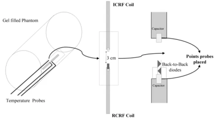
In the phantom heat experiments, a gel-filled bottle was used (Fig. 6). Both ICRF and RCRF coils were placed on the inner wall of a 5-liter bottle that had a diameter of 21 cm. The bottle was leaned against the bore of the MR scanner. The heating experiment used fast spoiled gradient-recalled (SPGR) using the following imaging protocol: TE⫽ 0.9 ms, TR⫽ 6.5 ms, flip angle ⫽ 90°, slice thickness ⫽ 20 mm, spacing⫽ 0 mm, matrix size ⫽ 256 ⫻ 128, FOV ⫽ 480 ⫻ 480 mm2, phases per location⫽ 15, NEX ⫽ 60, bandwidth
(BW)⫽ 62.50 Hz, and acquisition duration ⫽ 690 s. Neoptix ReFlex four-channel signal conditioner and T1
fiber optic temperature sensors were used to measure tem-perature (Neoptix, Inc., Quebec City, Canada). Since we expected the highest electric field around the capacitor, FIG. 4. Sketch of the upper end-ring part of the receive-only
bird-cage coil. The receive-only birdbird-cage coil has two feeds and an inductor-diode system is used for decoupling. Scanner-supplied direct current (DC) turns on the diode during RF transmission. Two back-to-back diodes are used for passive decoupling. Again, during the RF transmission, alternating current (AC) on the end-ring turns on diodes that detune the coil, resulting in effective decoupling.
FIG. 5. The RCRF coil. The RCRF coil is 4.0 mm in diameter and 85 mm long. It is constructed from 0.4-mm-diameter coated copper wire. The RCRF coil is tuned by a ceramic chip capacitor to 63.85 MHz using an HP 8753D network analyzer.
FIG. 6. Sketch of the heating experiment involving ICRF and RCRF coils. Two coils were placed on the inner wall of the gel-filled phantom. The phantom was leaned against the MR imager bore wall in order to obtain maximum heating. The coils were 3 cm from each other with the center of the MR imager bore between them. Two probes were placed on the tips of the coils and another one was placed midway between the fast spoiled gradient-recalled coils as a reference data probe. In the heating experiment we used fast SPGR with TR⫽ 6.5 ms and flip angle ⫽ 90° for duration ⫽ 690 s.
coil was shown to be safer to use and therefore the imaging experiments were conducted using only this type of coil. Phantom Imaging Experiments
Phantom imaging experiments were conducted to study the reverse polarization technique in ideal conditions. In these experiments, the RCRF coil was inserted into a gel-filled bottle. Sagittal images were taken using a gradient echo sequence with several flip angles (1°, 5°, and 40°). The following gradient echo parameters were used: TR/ TE⫽ 40 ms/3.4 ms; spacing ⫽ 1 mm; slice thickness ⫽ 20 mm; matrix size ⫽ 256 ⫻ 256; and FOV ⫽ 300 ⫻ 300 mm2.
Animal Imaging Experiments
Proof-of-principle animal experiments were done using the RCRF coil. The rabbit esophagus was chosen for ease of implementation (11) and also to test the design in one of the most challenging anatomical structures. The esopha-gus lies next to the trachea, aorta, great veins, lungs, and heart. In addition, air inside the esophagus makes it diffi-cult to visualize using MRI. The experiments conformed to the Guidelines for the Care and Use of Laboratory Animals, and were approved by the Gazi University ethics commit-tee, Ankara, Turkey. Two New Zealand and two Angora rabbits were used. General anesthesia was induced by intramuscular injection of 5 mg/kg of ketamine and 40 mg/kg of xylazine. Then the RCRF coil was lubricated and inserted via the mouth into the duodenum. The rabbit was then placed on an MR table and images were taken while the catheter with the RCRF coil was withdrawn through the esophagus. The motion of the tube inside the esophagus was recorded by fast gradient echo and steady-state free precession (SSFP) imaging sequences. The fast gradient echo parameters were as follows: TR/TE⫽ 7 ms/ 1.9 ms; matrix size⫽ 256 ⫻ 256; FOV ⫽ 300 ⫻ 300 mm2;
and acquisition time⫽ 1.8 s. The SSFP parameters were as follows: TR/TE⫽ 6.3 ms/1.7 ms; matrix size ⫽ 256 ⫻ 256; FOV⫽ 300 ⫻ 300 mm2; flip angle⫽ 40° slice thickness ⫽
20 mm; and acquisition time⫽ 1.6 s.
RESULTS
Phantom Heat Experiments
At 18.7°C, the thermal properties of the gel in the phantom were: thermal conductivity, K⫽ 0.51 W/mK; specific heat capacity, C ⫽ 3820 kJ/m3 K; thermal diffusivity, D ⫽
0.13 mm3/s. The density of the gel was 1150 kg/m3and
hence heat capacity was 4400 J/kg K.
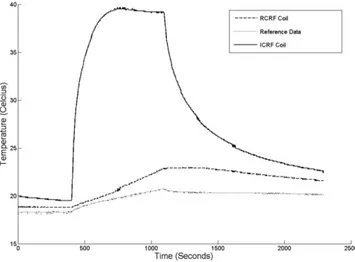
Both coils that are described in the Materials and Meth-ods section were used in phantom heat experiments. A temperature rise of 2.4°C was observed in 690 s (Fig. 7) in the reference location, suggesting that the applied SAR was 15 W/kg. Note that the SAR value estimated by the scanner is known to be unreliable (12) when phantoms are used; therefore we used this measured SAR as the applied SAR.
A sharp increase in temperature (15°C in 100 s) was observed at the tip of the ICRF coil (Fig. 7). This implies local heating around the tuning capacitor. The tempera-ture increased by 20°C over 320 s. The safety index (10) is calculated to be 1.3°C/(W/kg). In other words, 1.5 W/kg peak power is the maximum that can safely be applied. This will produce a maximum temperature of 2°C while the device is in the body.
The temperature of the RCRF coil, however, increased much less (4.1°C in 690 s). The temperature rise was linear in time, and therefore this heating was not local. This suggests that the RCRF coil is much safer to use. Detailed analysis is necessary to determine under what conditions this coil can be scanned safely.
As a result of this experiment, we chose to conduct the rest of the experiments using the RCRF coil.
Phantom Imaging Experiments
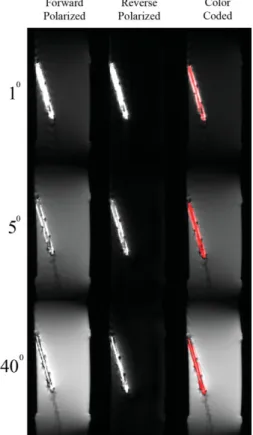
Figure 8 shows the results of the phantom imaging exper-iments; the forward polarization mode images are in the left column, reverse polarization mode images are in the center, and color-coded images are in the right column. The first row shows images with a 1° flip angle. Although a low flip angle was used, the catheter appeared bright, suggesting flip angle amplification. This can be explained by the fact that when a low flip angle is used, induced voltage across the back-to-back decoupling diodes may be FIG. 7. Plot of the heating experiment. A temperature rise of 2.4°C was seen in 690 s in the reference location. A sharp increase in temperature (15°C in 100 s) at the tip of the ICRF coil was observed. This implies local heating around the tuning capacitor; the temper-ature increased by 20°C over 320 s. However, the RCRF coil heated much less (4.1°C in 690 s).
lower than their turn-on voltage (0.3 V for the Schottky diodes). In this low flip-angle imaging case, the RCRF coil worked as an ICRF coil so that high contrast was achieved between the RCRF coil signal and the background signal. As the flip angle was increased (second and third rows in Fig. 8), background signal intensity increased. No over-tipping artifact (flip angles more than 90°) was observed around the catheter, which means a successful decoupling by the back-to-back diodes was accomplished; however, image contrast was decreased significantly.
In all conditions, our algorithm worked successfully, as can be seen in the reverse polarization images (mid-dle column in Fig. 8). The background signal is almost completely suppressed in all cases. The color-coded images enabled visualization of the catheter and the background.
Animal Imaging Experiment
The phantom has a uniform structure; therefore, the RCRF coil can be separated from the phantom easily. However, this is not the case in animal experiments because of the complex structure of tissues. As slice thickness and flip angle increase, visualizing the catheter becomes harder with standard imaging techniques.
Figure 9 shows the results of the rabbit experiments. As in the images from the phantom imaging experiment, the forward polarization mode of images, the reverse polariza-tion mode of images, and color-coded images are shown from left to right. Figure 9a– c are fast gradient echo im-ages, acquired using slice thicknesses of 5 mm and 20 mm, and without slice-selection. In addition, SSFP sequence images are shown in Fig. 9d; these are frequently used to guide interventional procedures.
In the first row (gradient echo images with a slice thick-ness of 5 mm and a flip angle of 1°), the catheter can be easily seen in the forward polarization mode image; in the reverse polarization mode image, background signal sup-pression was almost perfect. But with a flip angle of 40°, the catheter was barely visible in the forward polarization mode image, and the background signal suppression was almost complete in the reverse polarization mode image. Color-coding enabled visualization of the catheter against the background.
As slice thickness was increased (20 mm in Fig. 9b, no slice selection in Fig. 9c), visibility of the catheter de-creased significantly in the forward polarization mode im-age even with a flip angle of 1°. Identification of the cath-eter was almost impossible in the forward polarization mode image when a flip angle of 40° was used. On the other hand, background suppression was effective in both reverse polarization mode images. Again, color-coding en-abled visualization of the catheter within the background. As expected, visibility of the catheter in the SSFP se-quence was low in the forward polarization mode image, but background suppression in the reverse polarization mode image was successful (Fig. 9d).
DISCUSSION
A modified birdcage coil was manufactured to demon-strate the principles of the reverse polarization method.
Our algorithm is very suitable for real-time implementa-tion because it requires only one multiplicaimplementa-tion and one summation. Color-coding was already implemented in re-al-time (8). In addition, the reverse polarization mode im-age can be obtained by designing the receiver chain of the quadrature body coil so that the transmit channel is placed by a transceiver while retaining the standard re-ceiver channel. The signal received from the port that transmits the RF pulse reverses the polarization mode signal. By doing so, forward and reverse polarization modes can be obtained without any signal processing. From the manufacturing point of view, this is a rather straightforward modification of the scanner hardware, but we chose, as users, to redesign the coil ourselves.
The new method has not been implemented in a real-time imaging system. This will be essential if this method is to be useful in guiding interventional procedures. The processing power necessary to obtain reverse and forward polarization mode signals is minimal. Color-coding was shown to be possible in real-time (8).
Our method can be used not only in catheter-tracking procedures but also possibly in tracking other interven-tional devices. For example, tracking coils (13) may be replaced by RCRF coils. This will eliminate the need for electrical connections between interventional devices and scanner receivers (14), but needs further investigations.
In this study only phantom heat experiments were con-ducted. The exact conditions in which ICRF and RCRF coils can be used in MRI scanners needs to be investigated using detailed analysis backed by animal experiments and possibly with clinical tests. However, our results suggest that the heating around RCRF coils is significantly less than ICRF coils.
Currently, the use of implantable RF coils for high-resolution imaging of deep organs is under investigation (15). One problem with the high-resolution imaging tech-nique with implantable coils is image overlap. When a small FOV is used for high-resolution imaging, the large external coil receives signal from out of the region of interest. This unwanted signal occasionally causes image overlaps. If a reverse polarization mode signal is used, the signal directly picked up by these coils can be eliminated and high-resolution imaging without image overlap may be possible.
In order to obtain maximum SNR, a phased-array coil should be used to pick up the MRI signal, even if the signal is originating from inductively-coupled coils. Our reverse polarization mode method is currently designed for bird-cage coils. We have shown that it is possible to implement the reverse polarization signal using phased-array coils (16). We are currently working on a robust implementation of this technique.
CONCLUSION
The feasibility of background suppression using a reverse polarization mode signal in catheter tracking using ICRF coils was demonstrated. With a single birdcage coil, both reverse and forward polarization mode signals were ob-tained. Imaging of the target object with a real-time imag-ing sequence usimag-ing the forward polarization mode signal was possible and the catheter was distinctly seen in the
visualization of the catheter and the background.
FIG. 9. The animal imaging experiment. As in the phantom imaging experiment images, the forward polarization mode, the reverse polar-ization mode, and the color-coded images are shown from left to right. a–c: Fast gradient echo images, which were acquired using slice thicknesses of 5 mm, 20 mm, and without slice selection. SSFP se-quence images, which are frequently used in guidance of interventional procedures, are shown in (d). In the first row (gradient echo images with slice thickness of 5 mm and flip angle of 1°), the catheter can be easily seen in the forward polarization mode image; background signal sup-pression was almost perfect in the reverse polarization mode image. On the other hand, with flip angle of 40°, the catheter was barely visible in the forward polarization mode image, and background signal sup-pression was almost complete in the reverse polarization mode image. Color-coding enabled visualization of both catheter and background. As the slice thickness was increased (20 mm in (b), no slice selection in (c)), visibility of the catheter decreased significantly in the forward polarization mode image even with a flip angle of 1°. Identification of the catheter was almost impossible in the forward polarization mode image when a flip angle of 40° was used. On the other hand, back-ground suppression was effective in both reverse polarization mode images. Again, the color-coding method enabled visualization of the catheter against the background. As expected, visibility of the catheter in the SSFP sequence was low in the forward polarization mode image; on the other hand, background suppression in the reverse polarization mode image was successful (d).
reverse polarization mode signal. Color-coding enabled simultaneous visualization of catheter and anatomy with-out any restriction on the pulse sequence. The effective-ness of this method was tested by phantom and animal experiments. Clinical studies are needed to demonstrate the role of this technique in medicine.
ACKNOWLEDGMENTS
We thank Dr. Paul A. Bottomley for his continuous sup-port during this project. We are also grateful to Prof. Ayhan Altıntas¸ for his support, technologists Murat Tas¸demir and Kemal O¨ zdemir for their help in acquiring data, and Ms. Kirsten Ward for her valuable editorial support.
REFERENCES
1. Kochli VD, McKinnon GC, Hofmann E, Vonschulthess GK. Vascular interventions guided by ultrafast MR-imaging— evaluation of different materials. Magn Reson Med 1994;31:309 –314.
2. Atalar E, Bottomley PA, Ocali O, Correia LCL, Kelemen MD, Lima JAC, Zerhouni EA. High resolution intravascular MRI and MRS by using a catheter receiver coil. Magn Reson Med 1996;36:596 – 605.
3. Ocali O, Atalar E. Intravascular magnetic resonance imaging using a loopless catheter antenna. Magn Reson Med 1997;37:112–118. 4. Quick HH, Zenge MO, Kuehl H, Kaiser G, Aker S, Massing S, Bosk S,
Ladd ME. Interventional magnetic resonance angiography with no strings attached: Wireless active catheter visualization. Magn Reson Med 2005;53:446 – 455.
5. Burl M, Coutts GA, Young IR. Tuned fiducial markers to identify body locations with minimal perturbation of tissue magnetization. Magn Reson Med 1996;36:491– 493.
6. Quick H, Zenge M, Kuehl H, Kaiser G, Aker S, Eggebrecht H, Massing S, Ladd M. Wireless active catheter visualization: passive decoupling methods and their impact on catheter visibility. In: Proceedings of the 13th Annual Meeting of ISMRM, Miami Beach, FL, USA, 2005 (Ab-stract 2164).
7. Aksit P, Derbyshire JA, Serfaty JM, Atalar E. Multiple field of view MR fluoroscopy. Magn Reson Med 2002;47:53– 60.
8. Guttman MA, Lederman RJ, Sorger JM, McVeigh ER. Real-time volume rendered MRI for interventional guidance. J Cardiovasc Magn Reson 2002;4:431– 442.
9. Hayes CE, Edelstein WA, Schenck JF, Mueller OM, Eash M. An effi-cient, highly homogenous radiofrequency coil for whole-body NMR imaging at 1.5 T. J Magn Reson 1985;63:622– 628.
10. Yeung CJ, Susil RC, Atalar E. RF safety of wires in interventional MRI: using a safety index. Magn Reson Med 2002;47:187–193.
11. Shunk KA, Lima JA, Heldman AW, Atalar E. Transesophageal magnetic resonance imaging. Magn Reson Med 1999;41:722–726.
12. Baker KB, Tkach JA, Nyenhuis JA, Phillips M, Shellock FG, Gonzalez-Martinez J, Rezai AR. Evaluation of specific absorption rate as a dosim-eter of MRI-related implant heating. J Magn Reson Imaging 2004;20: 315–320.
13. Dumoulin CL, Souza SP, Darrow RD. Real-time position monitoring of invasive devices using magnetic resonance. Magn Reson Med 1993;29: 411– 415.
14. Susil RC, Krieger A, Derbyshire JA, Tanacs A, Whitcomb LL, Fichtinger G, Atalar E. System for MR image-guided prostate interventions: canine study. Radiology 2003;228:886 – 894.
15. Bilgen M, Al-Hafez B, He YY, Brooks WM. Magnetic resonance angiog-raphy of rat spinal cord at 9.4 T: a feasibility study. Magn Reson Med 2005;53:1459 –1461.
16. Celik H, Quick H, Zenge M, Atalar E. Wireless active catheter track-ing method ustrack-ing reversed polarization: implementation of 12-chan-nels phased array coil. ESMRMB, Warsaw, Poland; Abstract 258, 2006.