Compact left-handed metamaterial based on double-layer
planar metal strip arrays
K. Guven1,2, D. Caliskan2, and E. Ozbay1,2
1Department of Physics, Bilkent University, 06800 Ankara, Turkiye 2
Nanotechnology Research Center, Bilkent University, 06800, Ankara, Turkiye [email protected]
Abstract:. The existence of a left-handed transmission peak of a metamaterial consisting of
double-layer planar metal strip arrays at 15 GHz is demonstrated. This design is very suitable to submicron scales required at communication wavelengths.
©2006 Optical Society of America
OCIS codes: (160.1190) Anisotropic optical materials, (350.4010) Microwaves
The realization of artificial materials having a negative index of refraction [1], opened a new era for the electromagnetism [2, 3]. This is achieved by separately constructing negative permittivity (ε < 0) and negative permeability (µ < 0) planar components [4. 5], and then by combining many layers of them together periodically in the form of a composite metamaterial (CMM). The typical CMM is depicted in Fig. 1, which shows the periodic arrangement of wires (providing ε < 0 response) and the so-called split-ring resonators (SRRs) (providing µ < 0 response). The initial studies are mostly conducted in the microwave regime by virtue of the appropriate dimensions of the materials for fabrication and for experimental investigation. This is further justified by the scalability of the governing Maxwell’s equations so that the observed electromagnetic
phenomena can be projected to a wide range of operation frequencies across the electromagnetic spectrum.
Fig.1. Schematic of a conventional CMM consisting of periodically stacked layers of metallic wires and split ring resonators. The propagation of the electromagnetic wave is along the x direction, the electric field along the y direction.
Nevertheless, the realization of CMMs at communication- and ultimately at optical wavelengths brought serious concerns about the actual scalability of the structure from fabrication point of view. This issue basically stems from the conventional CMM design, where the wavevector of
a158_1.pdf
TuB7.pdf
the propagating electromagnetic field has to be in the plane of the layers. Then, the magnetic field (being normal to the layers) couples to the SRR components and induces a magnetic resonance, which exhibits itself as a negative permeability response for the entire CMM. Evidently, the lateral width of the CMM has to be sufficiently large in comparison to the
wavelength. For infrared and optical frequencies, this would necessitate a multilayer processing at submicron scales subject to very precise interlayer alignment of metamaterial components across tens of layers, which is extremely difficult.
Very recently, a novel design of CMM is proposed which incorporates cut-wire patterns instead of SRRs [6, 7]. The key feature is that the cut-wire patterns are located on both sides of a thin substrate layer. Under normal-to-plane propagation, the cut-wire pair behaves like an inductor together with the capacitive coupling between the edges of the pair. The resulting response is then a magnetic resonance which is very similar to that of a SRR. The remarkable property of this design is that the CMM width is now related to the size of the layer, which is easily adjustable. The number of stacked layers determine the CMM thickness along the propagation direction, and only few layers are required to achieve the desired left-handed behavior.
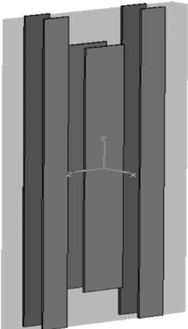
Motivated by these studies, we present an experimental and theoretical investigation of this new type of CMM at microwave frequencies. Our initial design has the operation frequency of 15 GHz. Figure 2 shows the schematic view of one unit cell of the CMM consisting of one cutwire with continuous wires on both sides. This double sided pattern is essential for proper operation. The structure is fabricated on dielectric boards deposited with 30 µm copper by etching. The propagation is along the x direction.
Fig. 2. Schematic view of one unit cell of the double planar cutwire/wire CMM. The gray shading represents the substrate layer. The cutwire is at the center, surrounded by the wires running continuously along the vertical direction. The propagation is normal to the CMM plane.
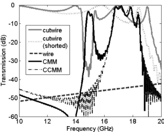
In Figure 3, the transmission spectrum simulations of the CMM structure and its individual components are shown. The cutwire pair structure (solid grey line) shows a resonance at around 15 GHz. In order to show that this resonance is of magnetic origin, we electrically short each
a158_1.pdf
TuB7.pdf
cutwire pair, turning them into a closed metallic loops. Since the current induced by the magnetic field can circulate freely, this eliminates the capacitance of the structure. The transmission
spectrum of this “shorted” cutwires are shown by dotted grey lines. We observe that the structure exhibits no resonance. We note that the cutwire and its shorted version also have a certain
electric response, which signals itself by the presence of second gap above 19 GHz [8]. The continuous wire structure is completely opaque throughout the shown frequency range. When we combine the cutwires and continuous wires together into a CMM, the corresponding transmission spectra exhibits a pass band in the common frequency range of respective µ < 0, ε < 0 gaps, around 15 GHz. The CMM has another pass band between 17-19 GHz. This band
appears due to the combined electric response of the CMM [8, 9], for which the onset of positive permittivity is at 17 GHz. This is supported by the spectrum of the complementary CMM
structure (CCMM) which incorporates shorted cutwires (thin dash-dotted line). This structure has almost identical electric response of the CMM, but lacks the magnetic response. As a result, only the second pass band is present. Thus, we conclude that the CMM acts as a left-handed medium within the first transmission band.
Fig. 3. The simulated transmission spectra of the CMM (solid black), cutwire (solid grey), shorted cutwire (dotted grey), wire (dashed), and complementary CMM (dash-dotted) structures. In its first transmission band around 15 GHz, the CMM acts as a left-handed medium.
In conclusion, we demonstrate the left-handed pass band of a CMM consisting of planar double-layer cutwire and continuous wire patterns. The experimental investigation of the transmission reflection spectra and the refraction properties of this structure is currently under progress.
1. V. G. Veselago, Sov. Phys. Usp. 10, 504 (1968).
2. D.R. Smith, W.J. Padilla, D.C. Vier, S.C. Nemat-Nasser, and S.Schultz, Phys. Rev. Lett. 84, 4184 (2000). 3. R.A. Shelby, D.R. Smith, S.C. Nemat-Nasser, and S.Schultz, Apl. Phys. Lett. 78, 480 (2001).
4. J.B. Pendry, A.J. Holden, W.J. Stewart, and I. Youngs, Phys. Rev. Lett. 76, 4773 (1996).
5. J.B. Pendry, A.J. Holden, D.J. Robbins, and W.J. Stewart, IEEE Trans. Microwave Theory Tech. 47, 2075 (1999). 6. G. Dolling, C. Enkrich, M. Wegener, J. F. Zhou, C. M. Soukoulis, and S. Linden, Opt. Lett. 30, 3198 (2005).
7. V. M. Shalaev, W. Cai, U. K. Chettiar, Hsiao-Kuan Yuan, A. K. Sarychev, V. P. Drachev, and A. V. Kildishev, Opt. Lett. 30, 3356, (2005). 8. T. Koschny, M. Kafesaki, E. N. Economou, and C. M. Soukoulis, Phys. Rev. Lett. 93, 107402 (2004).
9. K. Aydin, K. Guven, M. Kafesaki, L. Zhang, C. M. Soukoulis, and E. Ozbay, Opt. Lett. 29, 2623 (2004).
a158_1.pdf
TuB7.pdf