IZMIR KATIP CELEBI UNIVERSITY GRADUATE SCHOOL OF SCIENCE ENGINEERING AND TECHNOLOGY
Ph.D. THESIS
MARCH 2017
SYNTHESIS, CHARACTERIZATION AND APPLICATION OF NEW ORGANIC ELECTROACTIVE MOLECULES FOR PHOTOVOLTAIC
DEVICES
Thesis Advisor: Assoc.Prof. Dr. Şerafettin DEMİÇ Mesude Zeliha ARKAN
Department of Materials Science and Engineering
MARCH 2017
IZMIR KATIP CELEBI UNIVERSITY GRADUATE SCHOOL OF SCIENCE ENGINEERING AND TECHNOLOGY
SYNTHESIS, CHARACTERIZATION AND APPLICATION OF NEW ORGANIC ELECTROACTIVE MOLECULES FOR PHOTOVOLTAIC
DEVICES
Ph.D. THESIS Mesude Zeliha ARKAN
(D130111008)
Malzeme Bilimi ve Mühendisliği Anabilim Dalı
MART 2017
İZMİR KÂTİP ÇELEBİ ÜNİVERSİTESİ FEN BİLİMLERİ ENSTİTÜSÜ
FOTOVOLTAİK CİHAZLAR İÇİN YENİ ORGANİK ELEKTROAKTİF MOLEKÜLLERİN SENTEZİ, KARAKTERİZASYONU VE UYGULAMALARI
DOKTORA TEZİ Mesude Zeliha ARKAN
(D130111008)
Thesis Advisor : Assoc. Prof. Dr. Şerafettin DEMİÇ ... İzmir Katip Çelebi University
Jury Members : Assoc.Prof. Dr. Sermet KOYUNCU ... Çanakkale Onsekiz Mart University
Assoc. Prof. Dr. Cem TOZLU ... Karamanoğlu Mehmet Bey University
Assoc.Prof. Dr. Mustafa CAN ... İzmir Katip Çelebi University
Asst. Prof. Dr. Fethullah GÜNEŞ ... İzmir Katip Çelebi University
Mesude Zeliha ARKAN, a Ph.D. student of iKCU Graduate School of Science Engineering and Technology student ID 130111008, successfully defended the thesis
entitled “SYNTHESIS, CHARACTERIZATION AND APPLICATION OF NEW ORGANIC ELECTROACTIVE MOLECULES FOR PHOTOVOLTAIC
DEVICES
”, which she prepared after fulfilling the requirements specified in the associated legislations, before the jury whose signatures are below.
Date of Submission : 20 February 2017 Date of Defense : 10 March 2017
ACKNOWLEDGEMENT
I would especially like to thank my advisor, Assoc.Prof.Dr. Şerafettin Demiç, for his healthy degree of optimisms when experiments disappointed and all seemed lost. I would also like to thank him for the warm and friendly atmosphere he garnered in his group; it encouraged sharing of ideas, insightful discussions and a productive work environment.
Next, I would like to thank Assoc.Prof.Dr.Mustafa Can and Assoc.Prof.Dr.Cem Tozlu for their helps on my thesis.
Additionally, I would like to thank Assoc.Prof.Dr. Hüseyin Ertik, Res.Asst.Abdullah Bayram, Res.Asst.Eyyüp Yalçın and Cebrail Özbek for their kindly helps.
I want to thank my parents. It is with their help for all my life that I became who I am today. Thanks for always being there for me, believing in me, and motivating me to set out on my own path.
My special thanks go to my husband, Emre Arkan, for his helps and moral support. Finally, I want to thank TUBITAK for the 113M978 project support.
TABLE OF CONTENTS Page ACKNOWLEDGEMENT………ix ABBREVIATIONS………..xiii SYMBOLS………xvi LIST OF TABLES………..xvii LIST OF FIGURES……….xix SUMMARY………xxiii ÖZET………...xxv 1.INTRODUCTION………..………….………..25 1.1 Photovoltaic Cells……….….29 1.1.1. Organic photovoltaics……….…..31
1.1.1.1. Bilayer organic solar cell ………....…..30
1.1.1.2. Bulk heterojunction solar cell ………...31
Metal oxides……….35
Self-assembled monolayers………..36
1.1.2. Dye-synthesized solar cell………35
1.1.2.1. Dyes………...38
Metallic dyes……….38
Metal free organic dyes……….…38
1.1.2.2. Electrolyte……….…..39
DSSCs with solid electrolytes (ssDSSC)………...39
DSSCs with ionic liguids as electrolytes………...39
1.2 Characterization of Solar Cells………..40
1.2.1. Short circuit current (Isc)………..40
1.2.2. Open circuit voltage (Voc)………...41
1.2.3. Maximum power (Pmax), current at Pmax (Imp), voltage at Pmax (Vmp)………...41
1.2.4. Fill factor (FF)………..42
2. MATERIALS AND METHODE………....43
2.1. Synthesis of Molecules ………...43
2.2. UV-Visible Apsorption and Cyclic Voltammetry………...44
2.3. Kelvin Probe and Efficiency Analyses………44
3. RESULTS AND DISCUSSION………..….45
3.1. Synthesis and Structural Analyses………...45
3.1.1. SAM molecules……….……45
3.1.1.1.Synthesis of methyl 4-(5'-bromo[2,2'-bithien]-5-yl) benzoate……...45
3.1.1.2. Synthesis of methyl 4-(5'-phenyl[2,2'-bithiophen]-5-yl) benzoate (ZE-Ph)………...46
3.1.1.3.Synthesis of 4- [5 '- (4-methoxyphenyl) -2,2'-bithiophen-5-yl] benzoic acid (ZE-1MeO)……….46
3.1.1.4. Synthesis of 4- [5 '- (3,5-dimethoxyphenyl) -2,2- bithiophen -5-yl] benzoic acid (ZE-2MeO)…………...……….47
3.1.1.5. Synthesis of 4-[5'-(3,4,5-trimethoxyphenyl)-2,2'-bithiophen-5-yl]
benzoic acid (ZE-3MeO)………47
3.1.2.Dye molecules………52
3.1.1.6 Synthesis of 1-(hexyloxy)-4-iodophenol (1)………..52
3.1.1.7 Synthesis of (4-bromopheny)bis[4-(hexyloxy)phenyl]amine(2)……53
3.1.1.8 Synthesis of (4-{bis[4-(hexyloxy)phenyl]amino}phenyl) boronic acid (3)………53
3.1.1.9 Synthesis of 6-(4-{bis[4-(hexyloxy)phenyl]amino}phenyl)-1H,3H-benzo[de]isochromene-1,3-dione (4)………..54
3.1.1.10 Synthesis of 4-(4-{bis[4-(hexyloxy)phenyl]amino}phenyl)-7- oxo-7H-benzimidazo[2,1-a]benzo[de]isoquinoline-11-carboxylic acid (5)……..54
3.1.1.11 Synthesis of methyl 4-bromo-7-oxo-7H-benzimidazo[2,1-a] benzo[de]isoquinoline-11-carboxylate(6)………...55
3.1.1.12 Synthesis of methyl 4-[4-(diphenylamino)phenyl]-7-oxo-7Hbenzimidazo[2,1-a]benzo[de]isoquinoline-11-carboxylate (7)………….55
3.1.1.13 Synthesis of 4-[4-(diphenylamino)phenyl]-7-oxo-7Hbenzimidazo[2,1-a]benzo[de]isoquinoline-11-carboxylic acid (8)………56
UV-Visible Absorption Spectrums of SAM Molecules ... 57
3.2 3.2.1. SAM molecules ... 57
3.2.2. Dye molecules ... 58
Cyclic Voltammetry Results of SAM Molecules ... 60
3.3 3.3.1. SAM molecules ... 60
3.3.2. Cyclic voltammetry results of SAM molecules on ITO surface ... 62
3.3.3. Dye molecules ... 64
ITO/SAM Kelvin Probe Microscope Analyses ... 65
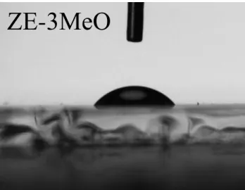
3.4 Contact Angle Results ... 67
3.5 Investigation of Electrical Characterization of Solar Cells ... 70
3.6 3.6.1 SAM molecules ... 70
3.6.2 Dye molecules ... 83
3.7. Incident Photon to Current Efficiency (IPCE) of SAM Molecules……….……82
CONCLUSION ... 85
4. REFERENCES ... 88
APPENDIX ... 96
ABBREVIATIONS
PV photovoltaic
OPV organic photovoltaic
CIGS copper indium gallium diselenide Cu(In,Ga)Se2 PCE power conversion efficiency
UV ultra viole Vis visible
BHJ bulk heterojunction
PC61BM PC61BM ([6,6]-phenyl-C61-butyric acid methyl ester) PC71BM PC61BM ([6,6]-phenyl-C71-butyric acid methyl ester) MEH-PPV poly[2-methoxy,5- (20-ethyl-hexyloxy)-p-phenylene vinylene)
MDMO-PPV poly[2-methoxy-5-(30,70-dimethyloctyloxy)-1,4- phenylene vinylene]
P3HT poly-3-hexylthiophene
HOMO Highest Occupied Molecular Orbital LUMO Lowest Unoccupied Molecular Orbital
ITO Indium tin oxide
HIL hole injection layer
PEDOT:PSS Poly (3,4-ethylenedioxythiophene) : poly(styrenesulfonate)
OSC organic solar cell
SAM self-assembled monolayer
HTM hole transport material
DSSC dye sensitized solar cell
ssDSSC solid state dye sensitized solar cell IL ionic liquid
FF fill factor
Pt theoretical power DME 1,2-dimethoxyethane THF tetrahydrofuran
NMR nuclear magnetic resonance FT-IR foruer transform infra-red TLC thin layer chromatography DMSO dimethylsuphoxide
SYMBOLS
λ wavelength
η efficiency
Imax current of maximum power point
Vmax voltage of maximum power point
Pin light power from source
Pmax maximum power
Imp current at maximum power
Vmp voltage at maximum power
Isc short circuit current
LIST OF TABLES
Page Table 3.1 : Photophysical parameters of MZ-341 and MZ-235 dyes. The molar
extinction coefficients in M-1 cm-1 are shown in parentheses. ... 59 Table 3.2 : HOMO and LUMO energy levels of SAM molecules ... 60 Table 3.3 : Oxidation potentials and HOMO energy levels of ITOs with SAM
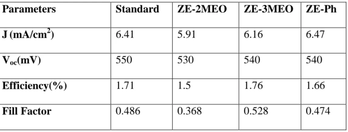
molecules ... 64 Table 3.4 : Contact potential difference between conductive tip Pt and substrate .... 66 Table 3.5 : Contact angle values of MoO3 and SAM coated MoO3 ... 69 Table 3.6 : Electrical parameters obtained from solar cells using different SAM
materials. MoO3 coated films were left in SAM for 24 hours. ... 70 Table 3.7 : Electrical parameters obtained from solar cells using different ZE-3MeO
SAM molecule. MoO3 coated films were left in SAM for 9 and 15 hours. ... 72 Table 3.8 : Electrical parameters obtained from solar cells using different SAM
materials. MoO3 coated films were left in SAM for 9 hours. ... 73 Table 3.9 : Electrical parameters obtained from solar cells using different SAM
materials. MoO3 coated films were left in SAM for 24 hours ... 74 Table 3.10 : Electrical parameters obtained from solar cells using different SAM
materials. MoO3 coated films were left in SAM for 12 hours. ... 75 Table 3.11 : Electrical parameters obtained from solar cells using different SAM
materials. MoO3 coated films were left in SAM for 9 hours. ... 76 Table 3.12 : Electrical parameters obtained from solar cells using different SAM
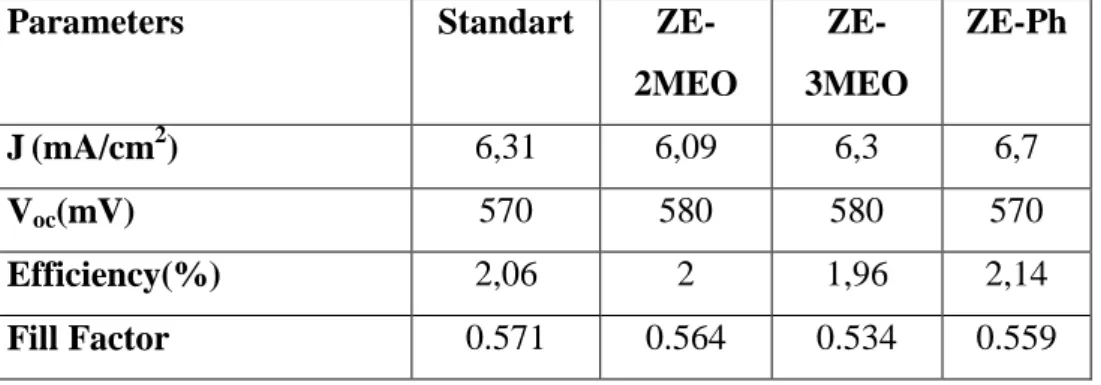
materials. ITO substrats were left in SAM for 20 hours... 78 Table 3.13: Average electrical parameters of cells with ITO/SAM/MoO3 anode electrode configuration………...…80 Table 3.14: The highest electrical parameters of cells with ITO/SAM/MoO3 anode electrode configuration……….……….….……80 Table 3.15 : Solar cell parameters for DSSC with MZ dyes. ... 84
LIST OF FIGURES
Page Figure 1.1 : A bilayer OPV, ideal bulk heterojunction and real bulk heterojunction
solar cells ... 31
Figure 1.2 : A schematic diagram showing the different parts of the SAM molecule ... 37
Figure 1.3 : DSSC’s schematic diagram ... 38
Figure 1.4 : Maximum Power for an I-V Sweep ... 43
Figure 1.5 : Getting the Fill Factor From the I-V Sweep ... 44
Figure 3.1: Molecule structures of SAM molecules ... 47
Figure 3.2: NMR spectrum of 4-[5'-(3,4,5-trimethoxyphenyl)-2,2'-bithiophen-5-yl] benzoic acid (ZE-3MeO)………50
Figure 3.3: FT-IR spectrum of 4-[5'-(3,4,5-trimethoxyphenyl)-2,2'-bitien-5-yl]benzoic acid………...51
Figure 3.4: Synthesis procedure of SAM molecules………..51
Figure 3.5: Structures of dye molecules……….52
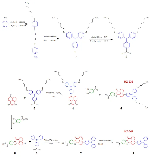
Figure 3.6: Synthesis procedure of MZ dyes……….57
Figure 3.7: Absorption spectrum of SAM molecules………....58
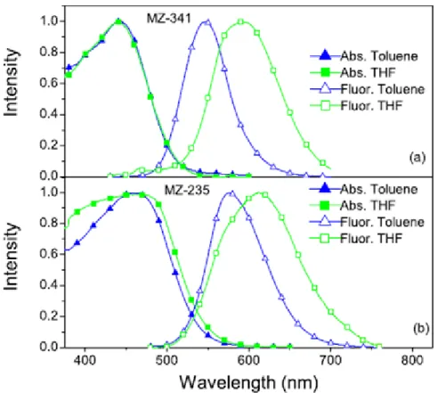
Figure 3.8: Absorption and Fluorescence spectrums of MZ dyes a)MZ-341 b)MZ-235………..59
Figure 3.9: Cyclic voltammogram of ZE-Ph………..61
Figure 3.10: Cyclic voltammogram of ZE-1MeO………..61
Figure 3.11: Cyclic voltammogram of ZE-2MeO………..62
Figure 3.12: Cyclic voltammogram of ZE-3MeO………..62
Figure 3.13: Cyclic voltammogram of ITO/ZE-1MeO………..63
Figure 3.14: Cyclic voltammogram of ITO/ZE-2MeO………..63
Figure 3.15: Cyclic voltammogram of ITO/ZE-3MeO………..63
Figure 3.16: Cyclic voltammogram of ITO/ZE-Ph………64
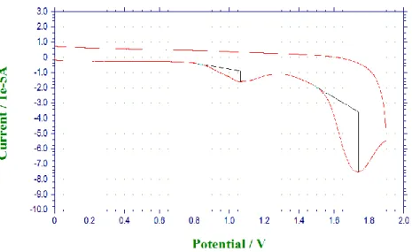
Figure 3.17: Cyclic voltammograms of MZ dyes a) MZ-235 b) MZ-341………….65
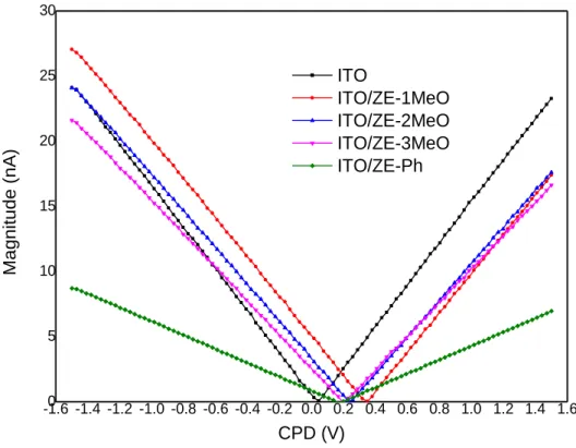
Figure 3.18: CPD results of ITO substrat and SAM coated ITOs………...66
Figure 3.19: Illustration of contact angles formed by sessile liquid drops on a smooth homogeneous solid surface………....67
Figure 3.20: Contact angle measuring photo of MoO3 and SAM molecules……....69
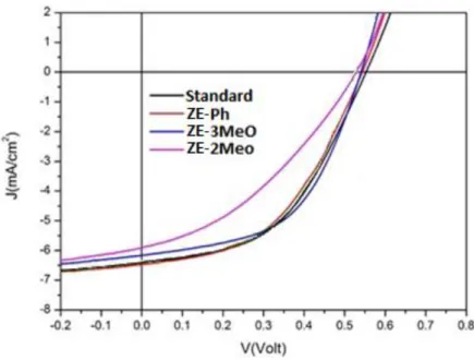
Figure 3.21: J-V graphs of solar cells prepared using different SAM materials…...71
Figure 3.22: J-V graphs of solar cells prepared using ZE-3MeO SAM molecule……….72
Figure 3.23: J-V graphs of solar cells prepared using different SAM materials………73
Figure 3.24: J-V graphs of solar cells prepared using different SAM materials………74
Figure 3.25: J-V graphs of solar cells prepared using different SAM
materials………..…76 Figure 3.26: J-V graphs of solar cells prepared using different SAM
materials………..77 Figure 3.27: J-V graphics of ITO/SAM/MoO3 cells………...79 Figure 3.28: J-V graphics of solar cells with ITO/SAM/MoO3 electrode configuration under illumination and dark………81 Figure 3.29: J-V curves of MZ dyes a) under light illumination (1.5 A.M 1000 W/m2) b) in dark………..…...82 Figure 3.30: IPCE curves of solar cells with/without SAM molecules….….…...….84
SYNTHESIS, CHARACTERIZATION AND APPLICATION OF NEW ORGANIC ELECTROACTIVE MOLECULES FOR PHOTOVOLTAIC
DEVICES
SUMMARY
PEDOT:PSS is with its acidic property solves the indium atoms from ITO and indium atoms diffuses in active layer in an organic solar cell. This event causes an decreasing in solar cell efficiency. In the same strategy, SAM molecules can be used as hole injection layer. On the other hand MoO3 can be used as anode buffer layer. In this thesis it is wanted to make SAM molecules have to not absorb visible range of solar spectrum for the efficient harvesting of solar energy by donor molecule. Otherwise the HOMO level of SAM molecule have to be between work function of ITO and HOMO level of donor molecule. In this way SAM molecules which don’t absorb the visible range of solar spectrum and with the suitable HOMO levels were designed, and applied on organic solar cell. On the other hand, while the series resistance in the solar cells to be formed with the synthesized molecules decreases according to the standard, parallel resistance increase is aimed.
DSSCs were proposed instead of silicon solar cells with their easy production and low cost fabrication. The photosensitizer which is liable for the visible and near-infrared utilization of the solar light, is one of the basic components of the DSSCs. Metal free organic dyes can be thought as an alternative for the solar energy to electricity conversion in DSSCs. One of the important parameter for the dye is harvesting solar energy efficiently. If the dye absorbs all solar spectrum more energy could be harvested. Furthermore, the energy levels of dye has to be suitable with TiO2 and hole transport material. On the basis of this we designed two metal free organic dyes for DSSC, absorbing uv-visible range of solar spectrum and having proper HOMO-LUMO levels, were designed, and applied on dye sensitized solar cell.
FOTOVOLTAİK CİHAZLAR İÇİN YENİ ORGANİK ELEKTROAKTİF MOLEKÜLLERİN SENTEZİ, KARAKTERİZASYONU VE
UYGULAMALARI ÖZET
PEDOT: PSS asidik özelliğiyle ITO'nun indiyum atomlarını çözer ve indiyum atomları bir organik güneş pilinde aktif katmanda dağılır. Bu olay, güneş pil veriminde azalmaya neden olur. Aynı şekilde SAM (kendiliğinden organize tek katman) molekülleri boşluk transfer katmanı olarak kullanılabilir. Bu tezde, SAM moleküllerinin donor tabakanın absorbsiyonunu engellememek için görünür bölgede absorbsiyon yapmaması istenmiştir. Ayrıca, SAM moleküllerinin HOMO enerji seviyesi aktif tabakanın HOMO enerji seviyesi ile ITO’nun iş fonksiyonu arasında olmalıdır. Buradan yola çıkarak bu tezde görünür bölgede absorbsiyon yapmayan, uygun HOMO enerji seviyeli SAM molekülleri sentezlendi. Diğer yandan, sentezlenen moleküller ile oluşturulacak güneş hücrelerinde seri direnç standarda göre azalırken paralel direncin artması hedeflenmektedir.
Boya duyarlı güneş hücreleri kolay ve düşük maliyetli üretimleri ile silikon güneş hücrelerine alternatif olmaktadır. Güneş ışığını absorblamakla görevli boya, boya duyarlı güneş hücresinin en önemli parametrelerinden biridir. Metal içermeyen organik boyalar, boya duyarlı güneş hücrelerinde güneş enerjisini elektriğe döndürmede kullanılan çevre duyarlı yapılardır. Boya için en önemli parametrelerden biri güneş enerjisini verimli bir şekilde soğurmaktır. Boya tüm güneş spektrumunu absorblarsa daha fazla enerji hasat edilir. Ayrıca boyanın enerji seviyeleri de boşluk iletim malzemesi ve TiO2 ile uyumlu olmalıdır. Bu bağlamda bu tez çalışmasında güneş spektrumunda UV-görünür bölgeyi absorplayan ve uygun HOMO-LUMO seviyelerine uygun boyalar sentezlenip uygulamaları yapıldı.
INTRODUCTION 1.
In the new global economy, energy and environment have become two of the most central issues in the 21th century [1]. Civilization of mankind has resulted in great success in industrial development and given rise to predicted extinction of non-renewable energy sources and irreversible wheather condition change. The population of Earth is almost 7.5 billion and people utilize energy in everyday to make life better, more productive and convenient. Over the decades, the energy consumption in the world have increased dramatically and ultimately reached a striking record of 8919 MTOE (million tonnes of oil equivalent) in the year of 2011 [2]. Vital part of energy that mankind uses is based on fossil fuels including petroleum, natural gas and coal that comprise big part of energy consumption in recent years [3]. The statistics have indicated that although global consumption in fossil based energy has accounted up to 80%, depletion of reserves is indispensable by the end of this century due to the continuous exploitation of human being [4]. Moreover, this consumption has resulted in excessive emission of greenhouse gases such as CO2, which has caused global warming. Based on the report of Intergovernmental Panel on Climate Change’s (IPCC), the overall average temperature of Earth has augmented by 0.5~0.8 oC since 1850 [5]. In the long term, three main alternatives can be proposed to decrease the CO2 emission, without any decrease in global energy consumption [6]:
Nuclear power; today there are around 440 nuclear power reactor operable around the world. They provide over %11 global energy demand.
Carbon sequestration; this concept enable us to use reserves of fossil fuels provided that we have to take care of emissions and storage of them in available cavities in the earth.
Sustainable energy; all required energy can be generated with these technologies by putting outstanding effort in developing existing and new techniques for sustainable energy production.
The initial option is not favorable and time limited solution due to the potential risk and finite amount of uranium reserve. The second alternative is neither sustainable solution nor tested method in large scale and therefore it is not for certain that it will work. Sustainable energy sources can be considered as the most promising alternatives and long term solution to be utilized [6].
From the perspective of energy level consumption, the values are not equally increasing all around the world [7]. For instance, consumption levels are relatively stable in Europe and these quantities will remain similar in the next 20 years according to predictions by the U.S. Energy Information Administration (EIA) [8]. Together with the European Union (EU), the individual governments have proposed goals associated with energy consumption and production. The following requirements have to be fulfilled until 2020 [9].
I. Emission of chemicals ( i.e. CO2, NOx, CH4 etc.) that cause greenhouse have to be decreased by 20%
II. 20% of energy demand should be supplied by renewable energy sources. III. Energy efficiency should be improved by 20% within the EU
In addition to aforementioned expectation, the EU has further long-term aims; until 2050, energy consumption should be decreased by 30% and greenhouse emission should be reduced by 80%. The administrations of five Nordic countries have declared even advanced goals for their own countries by intending reduction of greenhouse emission by 85% [10,11].
The desire for sources to produce more sustainable energy has appeared as an urgent problem. In this respect, the word of ‘‘sustainable’’ has more than one meaning. These energy sources should be both renewable and CO2 neutral. This group of preferred energy sources embraces: hydroelectric energy, wind energy, wave energy, geothermal energy, biomass-based energy and sun energy. Even though some of these energy sources including biomass-based, wind power and hydroelectric power are well-developed in a few EU states, fossil based fuels are still vital for energy supply in Finland, Denmark, and remaining part of the world [11]. Therefore, research into renewable energy technologies has been introduced as the key point for the sustainable future.
In general, within the concept of renewable energy, solar energy is described as the only inexhaustible source with large potential [12, 13]. It is generated as a result of continuous fusion reaction inside the Sun and the produced power is about 3.8×10²³ kW .The Earth’s upper atmosphere approximately can receive 1.7×10¹⁷ kW of radiated power. Inspite of all reflection from atmosphere and absorption in clouds, arriving solar energy receiving to oceans and landmasses of the Earth can reach to 8.0×10¹⁶ kW that is a tremendous energy source [14]. According to the International Energy Agency (IEA), the solar energy falling on earth in one hour was bigger than world annual energy usage in 2012. It is because of this, solar cells have demonstrated remarkable potential with considerably rapid growth [15]. More specifically, 139 GW total capacities had been installed all around the world until the beginning of 2014 [12,13]. With solar cell technology, this radiation, without any material consumption, can directly be converted into the most useful form of energy, electricity.
Photovoltaic Cells 1.1
The use of photovoltaic devices (PVs) is the simplest way of the direct alteration of solar energy into the electric power. The first practical PVs, developed by Daryl Chapin et al. at Bell Laboratory in 1954, was fabricated as p-n junction and reached power conversion efficiency (PCE) of 6%, which was also known as first-generation solar cell [16]. The mechanism of solar cell is rather simple. When a solar cell is subjected to illumination, the front and back sides are charged differently, and solar cell becomes a battery. The reason of this effect can be explained by two basic mechanisms. Incoming light is absorbed by electrons in solar cell and thereby promoted to higher energy level. While the electrons are elevated to a higher energy level, an oppositely charged hole remains behind them. An electric field formed in solar cell discrete these inversely charged particles by pushing them in different directions and lead to the oppositely charged front and backside of solar cell. Electric current flows after the connecting of back and front contacts with a load as long as solar cell is kept under illumination. This current enables electrons to come back to the solar cell at the lower energy level and the process can become repetable [6].
Today’s market, crystalline or polycrystalline silicon (Si) dominate over 90% of solar cell modules . There are many reasons having led to great achievement of
silicon based solar cell. The most important factors would be appropriate long-term stability and high PCE. Huge amount of silicon reserve (around 20%) on Earth crust is another advantage of this technology. However, production of high purity semiconductor materials is the first obstacle for all types of inorganic solar cell to reach ideal efficiency. Therefore, compare to conventional technology, this type of solar cells lead to ten times higher cost to generate same amount of electricity. Also, wafer technology is required for the fabrication of solar cell module that entail production Si wafers and soldering them together [6]. This results in further manufacture cost and complexity in production process.
Thin film solar cells are other types of photovoltaic system and called as second generation solar cell. It comprises several thin films with the thicknesses of 10µm or less that is deposited on low cost substrate. The advantage of this technology is that large scale and complete solar cell module can be produced in one piece via monolithic integration, which significantly lower the production cost compare to crystalline Si solar cells. So far, there are three thin film technologies, which are amorphous silicon (a-silicon), cadminium telluride (CdTe) and copper indium gallium diselenide Cu(In,Ga)Se2 (CIGS), candidate for large-scale production [6]. Despite industrial activity was relatively high, particularly for CdTe-based thin film solar cells, until 2002, industrial activity was closed during that year due to the lack of market acceptance corresponding to high amount of toxic element Cd used in this device [17].
Organic photovoltaic cell or Organic Photovoltaics (OPVs) are categorized as third generation solar cell. They are, basically, excitonic solar cell [18]; nevertheless, their physical properties are different from those of inorganic counterparts. Through researches conducted in this area, deeper knowledge has been gained by scientists and significant increase in PCE is obtained. Specifically, after the development of solution process for small molecules and polymer materials, this technology has become more exciting and has been subjected to great academic and industrial interest due to their easy adaptation to commonly used industrial techniques such as the wet coating and printing lines [19]. This progress resulted in fabrication of thin, low-cost and flexible plastic based OPVs. More recently, transparent electrodes and semi-transparent solar cells with broad absorption covering to UV region has been developed and used as building materials [20,21].
1.1.1 Organic photovoltaics
In 1959, Kallman and Pope first used anthracene molecules to make solar cell that is also accepted as the beginning of OPVs [22]. The field gained special interest and advanced further in 1970’s when conducting polymer were discovered and used for doping to achieve conductivities [23] . This discovery became famous and was awarded with Nobel Prize in Chemistry in first year of millenium gained by Heeger, MacDiarmid and Shirakawa [24]. Another important turning point was achieved by Tang in 1986, which was the utilization of the joining of two distinct molecules. One of the molecules is electron-donor and the other is electron-acceptor [25]. The introduction of C60 ([60] Fullerene) as a new acceptor group in 1992, by Sariciftci et.al and improvement of different device structure are other featured milestones of OPVs. Further developments have been focused on types of device structure, engineering of materials and processing conditions [26].
Organic Photovoltaic cells can be mainly classified as ‘‘Bilayer Organic Solar cell, Bulk heterojunction Solar Cell and Dye-Sensitized Solar Cell’’.
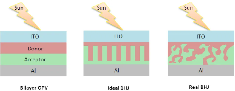
Figure 1.1 : A bilayer OPV, ideal bulk heterojunction and real bulk heterojunction solar cells
1.1.1.1 Bilayer organic solar cell
In bilayer solar cell, donor (p-type) and acceptor (n-type) materials are coated layer by layer. For the ideal device structure, 10-20 nm distances at donor-acceptor interface are theoretically required for electron-hole pair to reach the interface of layers. The higher distance brings about the quenching of the photon, low quantum yield and formation of minimum photocurrent[27].
In the early scientific researches, metal phthalocyanine has preferred as donor material together with acceptor C60 molecule in bilayer organic solar cell and
obtained PCE was reported around 3,6%. However, it was found that the obtained results were not repeatable [28]. Therefore, in this configuration (C60/MPc, M=Zn,Cu) the most reliable PCE was around 2,0-2,5% [29].
To further increase power conversion efficiency in bilayer organic solar cell, device fabrications were conducted by using several p-type organic materials. Particularly, tin phthaloyanine was introduced as an extra layer into the C60/CuPc system to change the absorption into the infra-red part of solar spectrum. But, reported PCE remained at around 1% [30]. In another study, boron- subphthalocyanine used as a donor material instead of Cu/Pc to increase open circuit voltage (Voc) [31]. Indeed, obtained Voc in this system was twice larger than that of found in C60/CuPc arrangement. However, the achieved PCE was only 2.1% owing to a decrease in short-circuit current density. A subsequent, more careful optimization of this combination provided PCE of about 3% [32].
Another strategy to make the performance of the bilayer solar cell better is based on utilizing different n-type materials. Pyrrolidinofullerenes bearing chelating pyridyl groups, which is derivatives of fullerene C60, have been used instead of nonmodified fullerene C60. Since this substance is highly soluble in organic solvents, it enables to fabricate films from solution by spin coating that is more efficient and economic process than vapor deposition. The main advantage of this compound is pyridyl groups on molecular structure because it can form complexes with zinc phthalocyanine at the border between donor and acceptor layers and increases the efficiency of charge separation in the donor and acceptor interface [33]. On another side, main disadvantage of this compound is organic moieties on the structure that remarkably impair electron transport ability of fullerenes. As a consequence, maximal PCE obtained for pyrrolidinofullerene/ZnPc cells is 1.6% [34-35].
It is probably that replacement of metal phthalocyanine with other organic donor is the most promising strategy for increasing performance of bilayer cells. It was indicated that combination of oligothiophene electron-donor material with fullerene acceptor provides PCE up to 3.4% that seems to be record value for bilayer solar cells.
1.1.1.2 Bulk heterojunction solar cell
Different from bilayer solar cell, in a bulk heterojunction (BHJ) solar cell donor and acceptor substances exist as a mixture in active layer. The practical reason of this is due to the solubility and applicability of organic substances in organic solvent. Therefore, it is possible to decrease the fabrication cost of device by depositing from solvent via modern printing technology. The main advantage of BHJ solar cell over bilayer organic solar cell is its superior PCE that is the consequence of high interface area between donor and acceptor materials. Therefore, efficient separation of excited charge can provide at around % 100 quantum yields in BHJ solar cell [36].
A short time ago, considerable progress has been taken place in BHJ solar cell by exceeding the barrier of %10 PCE [37]. Although a clear relationship between material properties and device performance has yet to be established, it is possible to tailor some electronic features such as absorption and energy levels during the synthesis. Considering the natural photosynthetic system, it is observed that highly ordered and conjugated self-organized nanostructures regulate the process of light absorption and charge separation [38]. Hence, arrangement of molecular packaging for advanced applications with organic materials is one of the most vital issues in the solar cells fabrication [39,40]. In the view of these researches, it is borne out that in addition to electronic structure, several parameters covering morphology of the materials has direct effect on device performance.
A p-type (donor) and an n-type (acceptor) semiconductor are the two components which can form interpenetrating networks through depositing simultaneously from solution, and therefore enable transport of charger carries to their relevant electrodes in BHJ solar cells. Most regularly preferred n-type materials are fullerene derivatives, such as PC61BM ([6,6]-phenyl-C61-butyric acid methyl ester) and PC71BM, in consequence of their low lying energy levels, reversible electrochemical reductions and solubility in organic solvents [41]. Moreoever, fullerenes have special π-conjugated systems and π-electron functionality in addition to their exceptionally high stability. In organic photoelectric conversion, fullerenes play a role that is difficult for other π-electron systems to fill and therefore still have the potential to bring about a revolution in solar cells [42].
The early OPV researches were mostly using poly[2-methoxy,5- (20-ethyl-hexyloxy)-p-phenylene vinylene) (MEH-PPV)/C60 composites that were then replaced by the better processable blend of poly[2-methoxy-5-(30,70-dimethyloctyloxy)-1,4- phenylene vinylene] (MDMO-PPV)/1-(3-methoxycarbonyl) propyl-1- phenyl[6,6]C61 (PCBM) [43-45]. However, since efficiencies of this combination remained at 3% at best [46-48] due to the low mobility and rather large band gap of the PPV-type polymers, general interest in this group of substance is faded. An important step in the progress of OPV cells is the usage of P3HT as a donor material. The prominent advantage of the P3HT is the formation of laminar structure when subjected to elevated temperature. Compare to MDMO-PPV system, P3HT provides high current density through improved charge transfer characteristic. Even though this characteristic makes P3HT the most general and popular donor material for many fundamental and conceptual studies, it has insufficient absorption in visible region and thus its maximum PCE remains at around %5. Since the structure of P3HT does not allow the structural modification to overcome this limitation, researchers have been looking for alternative organic moieties including co-polymers and small molecules.
Over the time, donor components have subjected to significant diversification and embrace polymer systems [41,49,50] and discrete molecules [51]. Most of sunlight-induced photoexcitations (excitons) take place in p-type (donor) materials because fullerene has limited absorption. Diffusion of electrons occurs until they reach a donor/acceptor border, where electron flows to acceptor material. [52] Electrons migrate through the acceptor and holes migrate through the donor phase to the respective electrodes. The related ideal donor materials should meet with some following requirements:
(1) wide-range and intense absorption in the solar spectrum’s low energy region to ensure effective light harvesting;
(2) deep (Highest Occupied Molecular Orbital) HOMO energy level to alter high Voc of OSCs[53];
(3) good solubility for solution-processing.
A combination of several parameters embracing structural insight, morphology control, polymer design and instrument engineering has given rise to PCEs
approaching 6-8.3% range for fullerene-conjugated polymer blends [54-61] and later this value has reached to 10.5% [62]. To fabricate efficient polymer based solar cells, the majority of reported papers use narrow bandgap conjugated polymers (as donor materials) together with a fullerene derivative (as acceptor materials). Nevertheless, the random nature of polymerization reactions bring about wide range in characteristics of molecular weight and finally in instrument performance.
It is well known fact that indium tin oxide (ITO) is frequently utilized electrode material for device fabrication from the point of view of large conductivity and high transparency. However, since substantial energetic mismatch exist at the interface of ITO and organic semiconductor, a direct hole-injection (extraction) from ITO to organic transport material is insufficient. This energetic mismatch entails high operation voltages to exceed the injection barrier that lead to decreased efficiency. Hence, different anode interfacial layers (or hole-injection layer (HIL)) can be inserted as hole-selective layer between the electrode and active layer to minimize hole- extraction barriers and to increase the performance of organic solar cells. A widely employed HIL is Poly (3,4-ethylenedioxythiophene) : poly(styrenesulfonate) (PEDOT:PSS) [63-64]. But, in addition to its solution with acidic nature (pH=1) that corrodes the ITO surface, the aqueous PEDOT:PSS dispersion brings about degradation owing to the existence of moisture as well as reduction in the lifetime of device [65-68]. Furthermore, work function of PEDOT:PSS is 5.0-5.1 eV, which can restrict charge injection into materials carrying high amount of ionization energy. Hence, it is significant to offer stable, friendly and promising alternative materials to be used as HIL rather than PEDOT:PSS in OSC [69].
Metal oxides
It should be indicated that transition metal-oxides such as tungsten-, vanadium-, nickel-, rhenium-, and molybdenum-oxides (WO3, V2O5, NiO, ReO3, MoO3) are currently focus of intense research instead of PEDOT:PSS [70-75]. In particular, transition metal-oxides have been ubiquitous cathode electrodes for Gratzel type electrochemical solar cells, inverted solar cells, and organic light emitting diode. In organic solar cell application, these materials can act as a buffer layer on metal electrodes due to their high permeability in visible region of solar spectrum, high semiconducting features, and high charge mobility values. The first studies associated with application of metal-oxide as anode electrode or hole-transport buffer
layer appeared in design of organic light emitting diode. The subsequent researches have focused on metal oxides to be utilized as a hole-transport layer to increase efficiency of hole- mobility through electrodes. Specifically, MoO3 has strongly n-doped by oxygen vacancies and indicate considerably deep lying electronic states [76]. It can evaporate at low temperature (~400oC) and therefore is feasible anode buffer layer for employing in OSC. According to the previous reports, vacuum-grown MoO3 exhibit electron affinity (EA) of 6.7 eV, work function (WF) of 6.9eV and ionization energy (IE) of 9.7eV, respectively [76]. Its fermi energy level is lower within the range of 0.5-0.2 than conduction band limit [77,78]. On the other hand, depending on stoichiometry and surface contamination, MoOx can possess various work functions. The example would be the exposure of oxygen and air, which lead to change in energy band levels. It can be concluded that since HOMO energy levels of polymers used in organic solar cells with high PCE chance within the range of -5.2eV to -5.6eV, thermally evaporated MoO3 use as an anode interlayer provides matching energy levels with related polymers [79].
Self-assembled monolayers
Self-assembled monolayers (SAM) of organic molecules can be defined as the formation of spontaneous molecular assembly on any surface due to the adsorption. SAMs are an affordable and useful surface coating for applications including sensitization, bio compatibility, molecular recognition for sensors, control of wetting and etc. SAMs molecules, comprise three main groups namely head group, tail and functional end group. There are various types of head groups with specific affinity for a substrate and metal oxides. For example, silane head groups are convenient for the substrate including HfO2 [80], ITO [81], PtO [82], TiO2 [80], ZrO2 [83] and alcohol based amphiphiles are suitable for the substrate such as FexOy [84], Si-H [85], Si [86]. Moreover, acidic head groups such as RCOO-/RCOOH have affinity to α-Al2O3 [87], FexOy [88], Ni [89], Ti/TiO2 [90] type substrates. SAMs can be created from either the liquid or gas phase onto a substrate surface via chemisorption that leads to slow organization of tail group. Over the period of minutes or hours, the head group assembles together on the substrate surface and results in formation of areas of close- packed molecules until single monolayer formed on substrate surface. Van der Waals interactions give rise to tight monolayer packs and thus reduce free energy of the surface [91]. The first example of the application of SAM molecules in
organic electronic device was shown in the study of organic electroluminescence where ITO surface was used as anode substrate and modified with SAM molecules, thereby reducing energy level between hole-transport materials (HTM) and anode material as well as increasing current density [92-96].
Figure 1.2 : A schematic diagram showing the different parts of the SAM molecule
1.1.2 Dye-synthesized solar cell
At the end of the last century, fabrication of robust large-scale solar cell based on molecular components for the feasible generation of electricity was considered to be utopic. But, the promising paper, written by O’Regan and Grätzel in 1991, encouraged researchers to compete in this challenge [97]. After the evolution of dye-sensitized solar cells (DSSCs), conventional solid-state photovoltaic technologies have confronted with big challenge by systems operating at a nano and molecular-level. DSSCs have proposed seminal features, for instance, for the small cells and minimodules, the obtained record efficiencies is about 12% and 9%, respectively as well as reached durable efficiency is of 8-9% with 1000h stability at 80oC. The cost-effective investments and easy fabrication are other advantages. Compare to other solar cell technologies, DSSCs operate relatively better under diffuse light condition and at elevated temperatures. DSSCs are also applicable to the flexible substrate with various shape, color, transparency and easy to integrate different products to come up with new commercial opportunities [98].
Figure 1.3 : DSSC’s schematic diagram
After the work of Grätzel et.al in the beginning of 1990s, high amount of work has been done for the development of a wealth of DSSC components and configurations. Essential working principles of the system have been understood through advanced characterization techniques and theoretical modelling of electrical and optical properties. The research in the synthesis of dyes (sensitizers) can be categorized into two main areas;
1-) Metal containing dyes; Functional ruthenium(II)–polypyridyl complexes such as N3 [99, 100], N719 (TBA+=tetra-n-butylammonium) [101, 99, 102], Z907 [103- 105], and black dye [106- 108].
2-) Metal-free organic donor-acceptor (D-A) dyes.
The synthesis of the compounds in the former class entails expensive ruthenium metal, careful synthesis and complicated purification process. By contrast, the second class can be synthesized by means of low-cost and well-known synthesis method. The outstanding features of metal-free dyes are their tunable electrochemical and absorption properties through convenient molecular engineering [109].
Amongst metal containing sensitizers, ruthenium(II)–polypyridyl complexes produce high efficiencies due to the wide absorption range covering visible region and extending to the near-infrared (NIR) regime. Additionally, bipyridyl group bears carboxylate moieties that decrease the energy of the anti-bonding π* orbital. Since
the electronic transition is defined as charge transfer from metal to ligand, excitation energy is efficiently given to the carboxylate moieties, from where electrons are poured into the conduction band of the semiconductor [110]. On the other hand, these dyes have moderate molar extinction coefficients (ε ≤ 20000 L mol -1 cm-1). In spite of the low absorptivity of nanostructured titanium dioxide (TiO2), its thickness on the conductive substrate can be changed to absorb almost all incoming light. But, with the help of fine engineering in structure of organic donor-acceptor dyes, high extinction coefficients can be obtained for all molecules [111]. Different from ruthenium (II) complexes, organic framework can be modified with various absorbing groups to adjust absorption and to achieve high extinction coefficients. DSSCs consist of five components such as i) photoanode, ii) semiconductor metal oxide, iii) sensitizer, iv) hole transport material/electrolide, and v) counter electrode. The sensitizer, anchored to the surface of semiconducting TiO2 nanocrystals, absorbs the incoming light. The charge separation occurs at the border by the way of photoinduced electron injection from the excited sensitizer (dye) into the conductive band of the semiconductor (TiO2). In the sensitizer’s (dye) ground state holes are formed, and regenerated via reduction by the HTM, which is regenerated by electrons at the counterelectrode with an external circuit. The efficiency of DSSCs depends on a well-known principle, namely, a hole-transporter should regenerate the sensitizer more rapidly with respect to the recombination speed of the conduction band electrons with the oxidized sensitizer. In addition to this principle, in order to regenerate the oxidized dyes effectively formed after electron injection into the conduction band of semiconductor (TiO2), by accepting electrons from hole tarnsport material (HTM), the HOMO of sensitizer has to be found under the energy level of hole transporter.
1.1.2.1 Dyes
The following criteria can be satisfied in an ideal dssc, namely; i) the dye must have broad absorption band and high molar extinction coefficient, ii) with the aim of an easy electron transfer, the lowest unoccupied molecular orbital (LUMO) of dye has to be above than the conduction band of TiO2, iii) for an efficient electron transfer from redox couple to dye, the highest occupied molecular orbital (HOMO) of dye has to be less than the energy level of redox couple, iv) the dye must have anchoring
groups such as -COOH, -SO3H, -PO3H, and v) the dye must have high light and thermal stability for long life time.
Metallic dyes
Metallic dyes are very suitable molecules for DSSCs due to their broad absorption band. Until now the best photovoltaic performance was obtained by using Rutenium (Ru) polipyridil complexes (N3, N719 and black dye) by Gratzel et.al. Addition to their high light characteristics, Ru dyes have an advantage namely injection of photoelectric charge to TiO2 via metal-ligand charge transfer. In Ru complexes, this transfer occurs faster than the recombination of oxidized electrons in dye [112].
Metal free organic dyes
There are some important factors for efficiencies of the dye and DSSC as follows:
Absorption range of dye must include all visible region and part of the near-IR region. Molar extinction coefficient has to be high possibly.
In order to provide an efficient electron injection into the anode, the LUMO of dye should be taken place near the anchoring group, i.e. a phosphonic or carboxylic acid, and, above the conduction band edge of the semiconductor electrode such as TiO2.
The energy level of redox couple must always be higher than HOMO of the dye.
The dye should not be aggregated on the surface in order to prevent the nonradiative decay that is from the excited state to the ground state, which is usually observed with thicker films [113].
In order to make the charge recombination minimum between the oxidized dye and the injected electrons, the positive charge occurred via electron injection process should be placed on the donor part, which is more away from the TiO2 surface [114-118].
In recent years, metal free organic dyes are spotlighted because of their economic availability and being eco-friendly feature. As examples of these important organic dyes, Coumarine, indoline, merocyanine, and triphenylamine can be shown with
their 7-9% efficiency. For a metal-free organic dye, the highest power conversion efficiency ever detected is about 12% [119].
1.1.2.2. Electrolyde
DSSCs with Solid Electrolytes (ssDSSC)
In solid state DSSC, a hole transport material (HTM) is used instead of liquid electrolyte which reduce the oxidized dye. Solid HTMs have less diffusion distance than liquid redox couple. Disadvantages such as solvent evaporation and leakage, encountered in applications are prevented even better with respect to IL-DSSCs. After many kinds of hole-transporting materials have been experienced in ss-DSSCs, it is found that the inferior pore filling of porous TiO2 films by the HTM makes the total efficiencies of solid state-DSSCs less than those for IL-DSSCs [120]. The efficiencies of above 5% have been reached by using solar cells which incorporate spiro-MeOTAD (2,2’,7,7’-tetrakis-(N,N-di-p-methoxyphenylamine)- 9,9’-spirobifluorene) or a highly conductive ionic polymer solid electrolyte as hole conductors and ruthenium(II)–polypyridyl complexes as sensitizers respectively [121-123].
DSSCs with Ionic Liquids as Electrolytes
In recent years, scientists have made Ionic liquids (ILs) to be useful as solvents or components of liquid and quasi-solid electrolytes for DSSCs [124-127]. Besides the reduced volatility due to negligible vapor pressure, the two important properties of ILs over organic solvents are thermal stability, and high ionic conductivity These mentioned properties provide a better long-term stability in solar cells. In terms of performance, the experimental comparisons show that devices with liquid electrolytes degrade faster than cells with ILs, which is undesirable for practical applications. Additionally, the electrochemical stability is kept at a higher level if ILs are used instead of liquid electrolytes. On the other hand, as a main disadvantage ILs usually show worse performance in devices due to their high viscosity, which leads to mass-transfer limitations on the photocurrent under highest illumination [128]. A thin nanocrystalline TiO2 film is required to approach high conversion efficiencies by virtue of the slow diffusion of I- and I3- ions in ILs due to their high viscosity. Due to these aforementioned reasons, metal-free organic dyes exhibiting high absorptivity behavior are suitable for DSSCs with ionic liquids (ILDSSCs).
Characterization Of Solar Cells 1.2
The characterization of organic solar cells is made by using current-voltage curve under the standard value of 1.5 AM and 100 mW/cm2 light. A solar simulator is needed for this purpose. Three parameters such as short circuit current (Isc), open circuit voltage (Voc) and fill factor (FF) are computed from current-voltage characterization. An example current-voltage curve of a photovoltaic cell is depicted in Figure 5. Short circuit current density (Isc) is measured under zero current. In this these, voltage applied to provide electromotor power is called Voc, Imax and Vmax are current and voltage of maximum power point respectively. Power efficiency is calculated by multiplication of data.
%ŋ=VocIscFF/Pin FF=ImaxVmax/IscVoc (1) Pin=light power from source
FF=fill factor
1.2.1 Short circuit current (Isc)
The short circuit current Isc is calculated when the voltage is zero, namely I (V=0) = ISC, and the short circuit condition occurs when there is low impedance. For an ideal cell, the highest current value is obtained when the total current is produced in the solar cell by photon excitation.
ISC = IMAX = Iℓ for forward-bias power quadrant
1.2.2 Open circuit voltage (Voc)
The term of open circuit voltage (VOC) determines the case of no current flowing through the cell, namely V (at I=0) = VOC. On the other hand, VOC corresponds to the maximum voltage difference across the cell for forward-bias sweep power quadrant, namely VOC = VMAX.
1.2.3 Maximum power (PMAX), voltage at PMAX (VMP), current at PMAX (IMP) The computation of power producing by the cell can be easily made by making use of I-V sweep and utilizing the well known equation P=IV. The zero and maximum values of power are observed at the ISC and VOC points, and between the two points, respectively. The maximum value of power is marked by PMAX point, and the voltage and current values at PMAX point are shown as VMP and IMP respectively.
Figure 1.4 : An I-V Sweep also identified PMAX [129]
1.2.4 Fill factor (FF)
The Fill Factor (FF) is used as the solar cell’s quality indicator. The calculation of FF is made by comparing the maximum and theoretical power (PT) with each other. The theoretical power (PT) is calculated in the case of both the open circuit voltage and short circuit current being together. For another definition of FF, the graphical interpretation can also be made by using the rectangular areas’s ratio depicted in Figure 1.5.
Figure 1.5 : Obtaining From the I-V Sweep The Fill Factor [129]
A higher FF corresponding a more square-like I-V sweep is desirable for optimum efficiency. Typical FF values range from 0.5 to 0.82, and are usually shown as a percentage.
1.2.5 Efficiency (η)
Efficiency is defined by the ratio of the output electrical power (Pout) to the input
solar power (Pin) entering the PV cell. Pout can be assumed as to be PMAX, because of
the getting maximum efficiency capability of the solar cell that can be utilized up to its maximum power output.
η= Pout / Pin → ηmax = Pmax / Pin (3)
Pin is defined as the product of the irradiance of the incoming light with the surface area of solar cell. In calculations, the irradiance of the incoming light and the surface area of solar cell are measured in W/m2 and m2 respectively. The maximum efficiency exhibits a sensitive dependence on the following factors such as; (i) the performance of the device under test, (ii) temperature and (iii) the spectrum and intensity of the incoming light, which are called as ambient conditions. Therefore, for an acceptable test, PV cells should be compared by using similar lighting and temperature conditions as much as possible [129].
MATERIALS AND METHODE 2.
Synthesis of Molecules 2.1
Supplier of 5-Bromo-5 '- (4,4,5,5-tetramethyl-3,2-dioxaborolan-2-yl)-2,2'-bithiophene was purchased from TCI. [4-(methoxycarbonyl) phenyl] boronic acid, benzene boranic acid, 4-methoxybenzeneboronic acid, 3,5-dimethoxybenzene boranic acid, 3,4,5- trimethoxybenzene boranic acid, 4-iodophenol, 4-bromoaniline, 1,2-dimethoxy ethane (DME), and N,N-dimethylformamide (DMF) is Alfa-Aesar. Potassium carbonate was obtained from Riedel de Haen. Supplier of 1-bromohexane and copper (I) iodide is Fluka; Supplier of 18-crow6, phenanthroline, n-butyllithium, tetrahydrofuran (THF), trimethylborate, 4-bromonaphthalene, 3,4-diaminobenzoic acid, [1,10-bis(diphenylphospino)ferrocene]dichloropalladium(II), acetone, dichloromethane and toluene is Sigma-Aldrich. Supplier of Zinc acetate and potassium carbonate is Riedel de Haen
No purification is done on any chemicals, solvents, and reagents received from commercial source. All glassware was oven-dried and all reaction was performed under inert (N2) environment.
.
UV-Visible Absorption and Cyclic Voltammetry 2.2
For the electrochemical measurements of MZ-341 and MZ-235 dyes CH 440B Instruments potentiometer was used. FT-IR measurements were made on a Thermo Scientific FT-IR Spectrometer with an ATR system (3000-650 cm-1). 1H and 13C NMR (Varian-400 MHz) data were made at 25 oC utilizing CHCl3-d and d6-DMSO as solvents and TMS as an internal standard. The absorption and fluorescence spectra were recorded utilizing a Termo Scientific UV-Vis spectrophotometer and a Hitachi F-2500 fluorescence spectrophotometer, respectively.
Kelvin Probe and Efficiency Analyses 2.3
Kelvin Probe analyses were carried out with NT-MDT Ntegra Solaris AFM. Xe light and a Solar Light Co. solar simulator (model 16S-300) was used for solar cells'
characterization by illuminating the samples.. The light intensity was 1000 W/m2 for all device measurements. At the end, the J-V curves were made by connecting the cells to a Keithley Source Meter (model 2601Aand 2200). Keithley computer software (LabTracer) controlled the process.
The ITO/MoO3/P3HT:PCBM/LiF/Al structure was taken as reference solar cell, and the ITO/MoO3/SAM/P3HT:PCBM/LiF/Al structure was prepared by using SAM molecules. In the first step DMSO solvent was used. Then the solvent was changed as DMF because of the wetness of DMSO.
In the solar cells a quasi-solid state electrolyte was used. This was prefered as it decreases the risk of leaks minimizing sealing problems in the cells while it combines the high ionic conductivity of liquids.
RESULTS AND DISCUSSION 3.
Synthesis and Structural Analyses 3.1
3.1.1 SAM molecules
Figure 3.1:Molecule structures of SAM molecules
3.1.1.1 Synthesis of methyl 4-(5'-bromo[2,2'-bithien]-5-yl) benzoate
A mixture of methyl-4-iodobenzoate (200 mg, 0.53 mmol) and 2-(5’-bromo-2,2’-bithien-5-yl)-4,4,5,5-tetramethyl-1,3,2-dioxaborolane (96.3 mg, 0.79 mmol) were dissolved DME (20 ml) in schlenk flask. Pd(dppf)Cl2 and K2CO3 were added to the mixture after temperature was reached to 50oC. The mixture was refluxed under N2 overnight. The reaction was monitored with thin layer chromatography (TLC) to establish completion. The final solution was then extracted with equal volume of CH2Cl2 and water. The organic solvent was removed under decreased pressure by utilizing a rotary evaporator and obtained crude product was purified by column chromatography (SiO2, CH2Cl/n-Hexane:1/1) to afford yellow powder as a product. 1H NMR (400 MHz CDCl3): δ 8.0-7.98 (d, 2H), 7.85-7.80 (m, 2H), 7.42-7.40-7.38 (t,1H), 7.25 (s, 2H), 3.86 (s, 3H).
3.1.1.2 Synthesis of 4-(5'-phenyl[2,2'-bithiophen]-5-yl) benzoic acid (ZE-Ph) A mixture of 4- (5'-bromo-2,2'-bit-5-yl) benzoate (200 mg; 0.53 mmol) and
benzeneboranic acid (96.3 mg; 0.79 mmol) were dissolved DME (20 ml) in schlenk flask. Pd(dppf)Cl2 and K2CO3 (2 ml; 1M) were added to the mixture after
temperature was reached to 50oC. The mixture was refluxed under N2 overnight. The reaction was observed with TLC to establish completion. The final solution was then extracted with equal volume of CH2Cl2 and water. The organic solvent was removed and obtained crude product was purified by column chromatography (SiO2, CH2Cl/n-Hexane:1/1) to afford yellow powder. Then, the product was dissolved in (1:1, V:V) THF-Ethanol mixture in round-bottom flask. KOH (0.5m; 1M) was added to solution and refluxed overnight. After all organic solvents were removed, the pure water (10 ml) and 1M HCl solution was added to flask until pH of the solution reached to region between 3 and 4. At the end, organic yellow product was precipitated, filtered, washed with pure water and dried overnight. 1H NMR (400 MHz CDCl3): δ 7.96-7.98 (d, 2H), 7.82-7.79 (d, 2H), 7.68 (s,3H), 7.54 (s, 1H), 7.44 (s, 4H), 7.37-7.31 (m, 1H).
3.1.1.3 4- [5 '- (4-methoxyphenyl) -2,2'-bithiophen-5-yl] benzoic acid (ZE-1MeO) A mixture of (5'-bromo-2,2'-bit-5-yl) benzoate (200 mg; 0.53 mmol) and 4-methoxybenzene boranic acid (120.1 mg; 0.79 mmol) were dissolved DME (20 ml) in schlenk flask. Pd(dppf)Cl2 (22 mg; 0.03 mmol) and K2CO3 (1M; 1 ml) were added to the mixture after temperature was reached to 50oC. The mixture was refluxed under N2 overnight. The reaction was observed with TLC to establish completion. The final solution was then extracted with equal volume of CH2Cl2 and water. The organic solvent was removed and obtained crude product was purified by column chromatography (SiO2, CH2Cl/n-Hexane:1/1) to afford yellow powder as a product. Then, the product was dissolved in (1:1, V:V) THF-Ethanol mixture in round-bottom flask. KOH (0.5m; 1M) was added to solution and refluxed overnight. After all organic solvents were removed under pressure, the pure water (10 ml) and 1M HCl solution was added to flask until pH of the solution reached to region between 3 and
4. Finally, organic yellow product was precipitated, filtered, washed with pure water and dried overnight. 1H NMR (400 MHz CDCl3): δ 7.95 (s,2H), 7.80 (s,2H), 7.67-7.62 (d,3H), 7.39 (s,3H), 7.00 (s,2H), 3.79 (s,3H).
3.1.1.4 4- [5 '- (3,5-dimethoxyphenyl) -2,2- bithiophen -5-yl] benzoic acid (ZE-2MeO)
A mixture of 4- (5'-bromo-2,2'-bit-5-yl) benzoate (200 mg; 0.53 mmol) and 3,5-trimethoxybenzene boranic acid (143.8 mg; 0.79 mmol) were dissolved DME (20 ml) in schlenk flask. Pd(dppf)Cl2 (22 mg; 0.03 mmol) and K2CO3 (1M; 1 ml) were added to the mixture after temperature was reached to 50oC. The mixture was refluxed under N2 overnight. The reaction was observed with thin layer chromatography (TLC) to establish completion. The final solution was then extracted with equal volume of CH2Cl2 and water. The organic solvent evaporated and obtained crude product was purified by column chromatography (SiO2, CH2 Cl/n-Hexane:1/1) to afford yellow powder as a product. Then, the product was dissolved in (1:1, V:V) THF-Ethanol mixture in round-bottom flask. KOH (0.5m; 1M) was added to solution and refluxed overnight. After all organic solvents were removed under pressure, the pure water (10ml) and 1M HCl solution was added to flask until pH of the solution reached to region between 3and 4. Finally, organic yellow product was precipitated, filtered, washed with pure water and dried overnight. 1H NMR (400 MHz CDCl3): δ 7.97-7.95 (d, 2H), 7.80-7.78 (d,2H), 7.67 (s,1H), 7.56 (s,1H), 7.41 (s,2H), 6.80 (s,2H), 6.48 (s,1H), 3.80 (s, 6H).
3.1.1.5 4-[5'-(3,4,5-trimethoxyphenyl)-2,2'-bithiophen-5-yl] benzoic acid (ZE-3MeO)
A mixture of 4- (5'-bromo-2,2'-bit-5-yl) benzoate (200 mg; 0.53 mmol) and 3,4,5-trimethoxybenzene boranic acid (167.5 mg; 0.79 mmol) were dissolved DME (20 ml) in schlenk flask. Pd(dppf)Cl2 (22 mg; 0.03 mmol) and K2CO3 (1M; 1 ml) were added to the mixture after temperature was reached to 50oC. The mixture was refluxed under N2 overnight. The reaction was observed with TLC to establish completion. The final solution was then extracted with equal volume of CH2Cl2 and water. The organic solvent was evaporated and obtained crude product was purified by column chromatography (SiO2, CH2Cl/n-Hexane:1/1) to afford yellow powder as a product. Then, the product was dissolved in (1:1, V:V) THF-Ethanol mixture in
round-bottom flask. KOH (0.5m; 1M) was added to solution and refluxed overnight. After all organic solvents were removed under pressure, the pure water (10ml) and 1M HCl solution was added to flask until pH of the solution reached to region between 3and 4. Finally, organic yellow product was precipitated, filtered, washed with pure water and dried overnight. 1H NMR (400 MHz CDCl3): δ 7.80-7.78 (d, 2H), 7.66 (s,2H), 7.52 (s,1H), 7.41 (s,1H), 6.92 (s,2H), 3.85 (s,6H), 3.67 (s, 3H).
Figure 3.2:NMR spectrum of 4-[5'-(3,4,5-trimethoxyphenyl)-2,2'-bithiophen-5-yl] benzoic acid (ZE-3MeO)
S S O OH H3CO OCH3 H3CO
Figure 3.3:FT-IR spectrum of 4-[5'-(3,4,5-trimethoxyphenyl)-2,2'-bitien-5-yl]benzoic acid.
Figure 3.4:Synthesis procedure of SAM molecules
S S O O H OCH 3 OCH3 OCH3
3.1.2 Dye molecules
Figure 3.5:Structures of dye molecules
3.1.2.1 Synthesis of 1-(hexyloxy)-4-iodophenol (1)
Potassium carbonate (5.6 g, 40 mmol), 18-Crown-6 (1 g, 4 mmol), 4-iodophenol (8.8 g, 40 mmol), and 1-bromohexane (6.6 g, 40 mmol) were dissolved in acetone (100 mL) in a round bottomed flask and refluxed with stirring overnight. The reaction was monitored with thin layer chromatography (TLC) to establish completion. The reaction was filtered after cooled down to room temperature, and the reaction mixture was extracted with diethylether (2 x 20 mL) and water (2 x 20 mL). The organic phase was separated then dried with sodium sulphate. The solvent was evaporated and column chromatography was used to purify crude product (dichloromethane/hexane: 1/1, V/V) to obtain a colorless oil (91%, yield). 1H NMR (400 MHz CDCl3): δ 7.50 (d, 2H), 6.63 (d, 2H), 3.87 (t, 2H), 1.76-1.70 (m, 2H), 1.44-1.39 (m, 2H), 1.34-1.29 (m, 4H), 0.89 (t, 3H). 13C NMR (400 MHz CDCl3): δ 138.37, 117.18, 68.35, 31.84, 29.41, 25.96, 22.87, 14.30.
3.1.2.2 Synthesis of (4-bromophenyl)bis[4-(hexyloxy)phenyl]amine(2)
CuI (0.2 g, 1 mmol) and phenanthroline (0.18 g, 1 mmol) were dissolved in toluene (10 mL) in a round bottomed flask. The reaction mixture was stirred under Dean-Stark apparatus and for half an hour. Potassium hydroxate (4.8 g, 77 mmol), 4-bromoaniline (1.65 g, 9.6 mmol), 1-(hexyloxy)-iodobenzene (5 g, 16 mmol), and toluene (20 mL) were added in to the flask and the mixture was refluxed overnight. The reaction was monitored with thin layer chromatography (TLC) to establish completion. The reaction was cooled down to the room temperature, then filtered with celite and washed with dichloromethane. Then the extraction was made with dichloromethane (3 x20 mL) and water (3x 20 mL). The organic phase was dried over sodium sulphate afte separating and the solvent was evaporated. Column chromatography was used to purify crude product (dichloromethane/hexane: 1/4, V/V) on silica gel to yield yellow oil (66% yield). 1H NMR (400 MHz CDCl3): δ 7.21 (d, 2H), 7.00 (d, 2H), 6.8 (d, 6H), 3.91 (t, 4H),1.78-1.72 (m, 4H), 1.46-1.42 (m, 4H), 1.36-1.32 (m, 8H), 0.90 (t, 6H). 13C NMR (400 MHz CDCl3): δ 168.37, 134.67, 131.33, 130.50, 128.98, 127.89, 127.24, 125.16, 110.48, 40.43, 40.23, 40.02, 39.81, 39.60.
3.1.2.3 Synthesis of (4-{bis[4-(hexyloxy)phenyl]amino}phenyl) boronic acid (3) (4-bromophenyl)bis[4-(hexyloxy) phenyl]amine (3.8 g, 7.3 mmol) was dissolved in dry THF (10 mL) and added to the round bottomed flask under argon atmosphere. The temperature was set to -80 oC with acetone and dry ice. N-butyl lithium (3.75 mL, 7.25 mmol) was dripped into the flask with care and stirred for thirty minutes. Trimethylborate (8.4 mL, 72.6 mmol) was dripped to the flask and stirred overnight. The reaction was monitored with thin layer chromatography (TLC) to establish completion. The product was extracted with 1 M hydrochloric acid aqueous solution (3 x30 mL) and diethylether (3 x 30 mL). The organic phase was dried with sodium suphate after separating, and the solvent was evaporated. Column chromatography was used to purify crude product (ethylacetate/ hexane: 3/1, V/V) on silica gel to obtain white solid (74% yield). 1H NMR (400 MHz d6-DMSO): δ 7.68 (s, 2H), 7.57 (d, 2H), 6.97 (d, 4H), 6.85 (d, 4H), 6.66 (d, 2H), 3.89 (t, 4H), 1.70-1.63 (m, 4H), 1.42-1.36 (m, 4H), 1.30-1.26 (m, 8H), 0.85 (t, 6H). 13C NMR (400 MHz CDCl3): δ
![Figure 3.19: Illustration of contact angles formed by sessile liquid drops on a smooth homogeneous solid surface [131]](https://thumb-eu.123doks.com/thumbv2/9libnet/3708882.24915/69.892.180.774.432.569/figure-illustration-contact-angles-formed-sessile-homogeneous-surface.webp)