3 (1), 2009, 25-39
©BEYKENT UNIVERSITY
STRESS ANALYSIS OF CORNER WELDING
JOINTS OF A MARTENSITIC STAINLESS
STEEL
Fehim FINDIK and Uğur SOY*
Dept. of Materials Technology, Technical Education Faculty, Sakarya University,
54187, Esentepe Campus, Sakarya, Turkey.
*: corresponding author, Tel: +90-264-2956503, Fax: +90-264-2956424, e-mail: [email protected]
Received: 20.11.2007, Revised: 10.07.2008, Accepted: 28.08.2008
ABSTRACT:
In this study, analysis in corner welding is aimed. In addition, T-welding (which is the other application of corner welding) is also examined. In this work, stress in welding notch and their effects on welding area are examined and the approach for the ideal case is also investigated. Marthensitic stainless steel is selected as a material in the experiment. For the analysis, finite element method is used and ANSYS 7.0 CAE Software program is also employed. Results are shown in graphs and critical cases are also defined. Stress value in welding root formed more than the stress in the upper foot tip. The big stresses can reduce the lower values within very small distance. According to all results except shear stress, minimum stress values formed in the root of welding in case of opening a welding mouth of 450.
Keywords: Stainless Steel; Stress; Joining; Welding; Finite Element Method
MARTENZITIK PASLANMAZ ÇELIĞIN KÖŞE
KAYNAK BAĞLANTISININ GERILME ANALIZI
ÖZET
Bu çalışmada köşe kaynağındaki gerilme analizi incelenmiştir. İlaveten köşe kaynağının diğer bir uygulaması olan T kaynağı analizi de araştırılmıştır. Kaynak ağzındaki gerilme ve bu gerilmenin kaynak bölgesine etkisi incelenmiş ve ideal duruma yaklaşımı da araştırılmıştır. Deneyde malzeme olarak martenzitik paslanmaz çelik seçilmiştir. Analiz için sonlu elemanlar metodu ve program olarak ANSYS 7.0 CAE yazılımı kullanılmıştır. Sonuçlar
grafiklerde gösterilmiş ve kritik durumlar da tanımlanmıştır. Alt kaynak ayağındaki gerilme değeri üst ayak da oluşan gerilme değerinden daha fazla oluşmuştur. Yüksek gerilimler çok küçük mesafeler aralığında azalabilir. Beklenen kayma gerilmesi değerlerinin genel sonuçlarına göre minimum gerilme değerleri, 450 kaynak ağzı aralığı durumunda kaynak bölgesinin alt kısmında oluşmuştur.
1. INTRODUCTION
Welding zone is heated locally by the welding heat source, temperatures in the vicinity of the weldment are not uniform but change with distance from the weld centerline. Due to the localized heating, complex thermal stresses are inevitably generated during welding. Residual stresses are stresses that remain in a material as a result of liquid-to-solid phase transformation associated with weld solidification and the subsequent non-uniform cooling of the weld altered by phase transformation (martensite transformation) in the solid state which most of ferrous b.c.c weld materials experience during rapid cooling after welding. It is well known that, in steel weldments, the solid-state transformation on cooling of austenite to martensite could have a major influence on the formation of residual stresses [1,2]. In joining system, the welding stress zone may be important when assessingth e risk for static fracture containing materials with brittle fracture behaviour. For example, a large tensile axial residual stress in the Heat Affected Zone (HAZ) at the inner surface of a stainless steel material is believed to be one of three factors responsible for intergranular stress corrosion cracks. However, the shape of the welding residual stress field depends on several factors like the structural restraint, the wall thickness over diameter ratio, the heat input, the number of weld passes and weld pass sequence. Hence, the through-the-thickness variation of the residual stress components may be very complex. A collection of experimental and numerical results and an attempt to provide an empirical relation for the axial residual stress on the inner surface (as a function of the heat input over wall thickness) is given by Scaramangase t al. [3,4].
For butt welds with larger wall thicknesses, and resulting more complex through-the-thickness temperature gradients present during welding, the magnitude of the residual axial stress may be much lower than the yield stress value. As current codes still often assume tensile axial stresses at the inner surface of yield stress magnitude and a rather large zone of tensile axial stressesn ear the inner surface , the assessmenot f crack growth may be unnecessarily conservative [5,6,7,8]. The process of mechanical stress relief involves pre-stretching the joint in order to eliminate the residual stress causing misfits by plastic straining. Since mechanical pre-stretching is not a thermal process it would appear to be more attractive for application to welded joints of dissimilar steels than a conventional stress relief heat treatment. This avoids the diffusion of carbon and the difference in thermal expansion properties of the two steels is unimportant [9,10,11]. To determine strength of
welding joining, stress, strain, carry-load capacity, performance of connection, deformation behaviour should be found out. Engineering calculations and experiments used to obtain the static values (stress, strain, deformation, etc.) Unfortunately, these methods have a long time and high cost. To cope with disadvantages, computer aided modelling techniques are propagated. Modelling techniques make simplicity for calculations. Also, there are no along time and high cost for establishing model. [12,13,14,15]. Fricke [16], a paper was published that the technique developed for numerical simulation of the welding process has not only been properly verified and validated on austenitic pipe welds, but that it also permits making selective statements on improvements to the welding process. For instance, numerical simulation can provide information on the starting point of welding for every weld bead, the effect of interpass cooling as far as a possible sensitization of the heat affected zone (HAZ) is concerned, the effect of gap width on the resultant weld residual stresses, or the effect of the 'last pass heat sink welding (welding of the final passes while simultaneously cooling the inner surface with water) producing compressive stresses in the root area of a circumferential weld in an austenitic pipe. Raymond [17], finite element analyses of standard tailor-welded blank (TWB) forming tests was performed to determine the effects of weld modelling techniques on simulation results. Finite element models of TWBs were created that either included a simple representation of the weld properties and geometry or excluded both weld geometry and material properties. In all models, shell elements were used to represent parent materials of the TWB. Results indicate that there are a number of relatively subtle effects associated with the manner in which the weld line is modeled. Most of these effects relate to the constraining effect of the weld line with respect to strain along the axis of the weld line. Zhang [18], a paper presents a computational model to predict residual stresses in a girth weld (H4) of a BWR core shroud. The H4 weld is a multi-pass submerged-arc weld that joins two type of 304 austenitic stainless steel cylinders. An axisymmetric solid element model was used to characterize the detailed evolution of residual stresses in the H4 weld. In the analysis, a series of advanced weld modelling techniques were used to address some specific welding-related issues, such as material melting: re-melting and history annihilation. The analysis results obtained from these studies shed light on the residual stress characteristics in core shroud weldments and the effects of residual stresses on stress corrosion cracking behaviour. Sarkani [19] a study investigates the residual stress fields in a welded T-joint, comparing those computed by 3D models with those computed by 2D models. The study shows that the temperature distribution in the central zone of the joint can be captured successfully by a 2D finite element model and a technique that takes into account the heat transfer balance and welding speed. The residual stresses in the plane of the 2D model computed by this method show fairly good agreement with those computed by the 3D model. More substantial differences are observed in the out-of-plane stresses, which are attributed primarily to the different mechanical boundary conditions in the out-of-plane direction of the 2D and the 3D models.
Lie [20] describes a systematic method in a paper of modelling the weld thickness of a tubular Y-joint. The intersection between the chord and the brace members is defined precisely. This intersection curve will then be used to evaluate the dihedral angle g, which is the angle between the chord and the brace surfaces along the intersecting line. As the dihedral angle g is an important parameter used to determine the weld thickness, its variation along the intersection curve and its relationship with the weld thickness is investigated first. Finally, some tubular welded specimens are fabricated, and the outer weld profiles are measured physically. It is shown that scale factors Fosouter =0.3, Fosinner =0.25 and constants m=2.0, n=0.4, are adequate to satisfy the required minimum outer weld profile. Therefore, the proposed method to model the weld size is both consistent and accurate for any tubular Y-joints. Pang [21] showed that a wide combination of weld toe angles and toe radii are possible. In a measurement of actual weld toe profiles experimental and finite element analysis of stress concentration and stress distribution was carried out for a particular cruciform welded joint. Closed-form stress pattern equations were compared from different sources. Stress intensity factor calculations using closed-form integration and weight function methods were carried out for weld toe cracks. Clubley [22], Bi-Steel is a system of double skin steel-concrete-steel construction. Units comprise of steel plates connected by an array of transverse friction welded shear connectors and filled with concrete. The experimental and numerical analysis of the shear strength of each friction weld subject to push out load is discussed in this paper. Finite element analysis using nonlinear discrete element models has been used to examine the local behaviour of concrete filled panels. Results from finite element analysis have been compared with experimental data for accuracy and behaviour trends. Conclusions drawn indicate the presence of several possible failure modes in the shear connection.
The aim of the present study is to analyze of T corner welding via finite element method. In this work, stress in welding notch and their effects on welding area are examined and the approach for the ideal case is also investigated. Marthensitic stainless steel is selected as a material in the experiment. For the analysis, finite element method is used and ANSYS 7.0 CAE Software program is also employed. Results are shown in graphs and critical cases are also defined.
2. DESIGN AND ANALYSIS
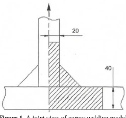
In the present study, characteristic joint is shown using the model in Figure 1. For the present work, a corner welding and a T welding are examined by 4 models using 15o of mouth angle between two metallic parts and for the
J
2 0%
1
X 4 0ilk
l i i i i
Figure 1. A joint view of corner welding model.
It will be adequate to analyze the area with dashed line in Figure 1. This is the routine case in the analysis with finite element method due to simplifying the model and saving time. Schematic views for corner and T welding are shown in Figure 2.
(a) (b)
Figure 2. Schematic view for corner welding (a) and T welding (b).
As a result of this definition, the points on symmetrical axis strain on longitudinally but not horizontally. The applied load in the system is on the longitudinal direction and therefore it is same for two sides of the joined part. Elastic modulus and Poisson ratio are assumed as E = 210 GPa and u= 0.29, respectively. It is also assumed that welding filler materials are the same properties with the original materials. A distributed tensile force as 1 MPa was applied from the top of the perpendicular material and the horizontal part was fixed from the bottom side. The model was geometrically examined and therefore heat affected zone (HAZ) and diffusions in materials were ignored. The lower and upper base length of welding seam was T = w = 30 mm for unprepared welding mouth and for the other cases it changed according to the
angle of welding mouth. Welding mouth was not prepared in the joints shown in Figure 2 (a) and in the other case; welding mouth of 45° was prepared illustrated in Figure 2 (b). It was seen from these figures that models were symmetrical and during the calculation, half of the model was considered and the solution was done using the axial symmetrical property of finite element method. When examining of Figure 2 (b), it is obviously seen that welding seam of T welding entered into the perpendicular material. In these two models, the lengths of lower welding base and mouth were taken as equal.
In Figure 3, a corner welding joint was seen illustrated in main features. In this figure, |BC| line is lower welding base and |BA| is upper welding base. In addition, |BD| line shows welding mouth. The angle between |BD| and |BC| lines are 45°, this position changes with the angle of welding mouth. On the other hand, the angle of welding mouth (a) is the angle of |BA| line with the vertical axis. In Figure 3, welding mouth (a) is shown as 15°. If this angle is 0°, it is defined as a corner welding. If this angle (a) is 45°, it is mentioned from "T" welding; if a goes from 0° to 45°, the upper welding base |BA| is increased and welding mouth approaches to |BD| line. If a is 45°, the upper welding base and welding mouth are coincided. The lower welding base of |BC| and welding mouth of |BD| change while a increase, whereas |AC| welding seam does not change. It is understood by comparing of how affect the angle of welding mouth to stress concentration via examining of the stress and shear values in these area while changing the angle of welding mouth. Corner and T welding in the dashed area in Fig. 1 was parametrically modeled using Catia 5R10 CAD Software program according to their welding mouth angle and then it was arranged in ANSYS 7.0 CAE Software and used. During the modeling, it was assumed that material properties of joined metallic parts and welding seam metal were the same. Sub model stated also the other side of the part due to symmetry. In that problem, due to not applying of a force or moment trying to demolish the symmetry, boundary conditions were the same for both sides. The corner welding of the transmission having 30 mm radius and the flange of 100 mm is shown in Figure 1 as dashed model. T welding model of totally 30 mm lower base of seam, double sided inner corner welding and again 30 mm lower welding base is seen in Figure 1. It is assumed that the
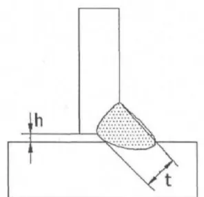
lower flange is embedded from the lower surface. In transmission and flange model, symmetry is also defined for the present analysis. In practice while making this kind of welding, it is not possible to contact completely both elements to each other. Due to surface roughness and application difficulties, an absolute blank will be remained between two elements. This blank is shown as h in the standard of ISO 6520. The defined tolerances within three classes of this blank are shown in Figure 4 and the tolerances are given as follows: h value is limited as "h < 1 mm+ 0.3 t ; max.4 mm" in Moderate (D) group, h value is limited as "h<0.5 mm+0.2 t; max.3 mm" in Intermediate (C) group, h value is limited as "h < 0.5 mm+ 0.l t ; max.3 mm" in Stringent (B) group, In the present model, h (blank for seam bottom) was obtained as 0.02 mm. In the tips of seam bottom blank, a rounding was made of the radius as 0.01 mm avoiding a sharp transition. Sharp transitions are one of the handicaps met during the analysis in finite element method. Therefore, some assumptions are made to gain better results. Here, a blank for seam bottom behaves similar to a crack. This is an undesired situation for both fatigue and fracture mechanics points of view.
h
Figure 4. Blank for welding seam bottom and welding mouth (neck).
In the present model, boundary conditions are as follows: the bottom of the model is embedded and so as deformation values of UX and UY for the points on the base line are taken as 0. The model is defined symmetrically from the left side and deformation of the points on this line is permitted only in UY direction. On the other hand, a distributed l MPa tensile force is applied from upper side of the model.
3. RESULTS
From the angle of 0o to 45o, for the opening welding mouth in each 15o of
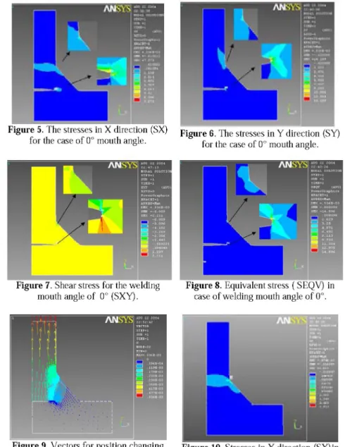
angle, only the values in the first and last degrees of angles were taken into consideration and the results were reported. Examining of Figure 5, it was seen that the maximum normal stress was formed in the root of welding and its value was realized as 7.273 MPa of nominal stress. In the general of the model, the small stress values were obtained and shown in blue color. The reason of the values of small stress was due to affecting of load in perpendicularly in X axis and no causing to bigger strains in X axis. The maximum stress value was so small and it occurred in almost in a point area and it showed a bigger decrease in a short distance. Examining of Figure 6, the maximum normal stress in Y direction was formed in welding root and its value was realized as 14.189 MPa of nominal stress. In this figure, the dominant color was also blue. Once more, the maximum stress was formed in very small area. The maximum stress value was in the root of welding. In addition to this, the stress value in welding root formed more than the stress in the upper foot tip and this was understood from the color scale. The big stresses can reduce the lower values within very small distance. Investigating of Figure 7, the maximum and minimum numerical values of shear stresses formed in welding root. When stating as absolute value, the maximum shear stress is realized as 6.009 MPa of nominal stress. The shear stresses were unimportant comparing to other stresses. The dominant yellow color in the model showed the value near to zero. Closing to the upper welding support, the stress welding values increased and this was expected situation. The upper welding support was forced to shearing. Examining of Figure 8, the maximum equivalent stress formed in the welding root and its value was realized as 14.596 MPa of nominal stress. Yet again, a dominant color was obtained as blue. The equivalent stress in the upper welding tip was obtained as 4.871 MPa of nominal stress. Blue color transformed to pale color towards the upper parts of the model, which is stresses increased due to decreasing of cross section. In Figure 9, position changing is seen in vectors. In this illustration magnitude, color and direction of arrows show a differentiation. Whenever arrows increase, they approach to red color. It is seen from this figure that the biggest arrows are on top of the model. Their directions are in the directions of applied load. It means that maximum strain of nodes was 0.536*10-3 mm and the most strain changed area
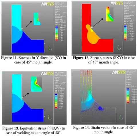
takes place on top of the model. In the neck of welding, it is noticed that strain lines became frequent. These lines point a stress concentration. Investigating of Figure 10, maximum normal stress in X direction formed on top of the welding tip and its value was realized as 1.611 MPa of nominal stress. This stress tried to shear the material and it realized a similar value to applied nominal stress. This was an expected result. Examining of Figure 11, maximum normal stress in Y direction formed on top of the welding tip and its value was recognized as 4.027 MPa of nominal stress. Examining of Figure 12, the maximum and minimum values of shear stresses formed on upper welding tip. If stating the stresses absolutely, the maximum shear stress was realized as
1.641 MPa of nominal stress. It is seen from Figure 13 that the maximum equivalent stress formed on upper welding tip and its value was realized as 3.69 MPa of nominal stress. It is seen Figure 14 that the most strained nodal area are seen on top of the model comparing to unloaded position of that model. Maximum value of strain amount is 0.47*10-3 mm.
Figure 5. The stresses in X direction (SX) F i g u r e 6 T h e s t r e s s e s i n y d i r e c t i o n ( S Y)
for the case of 0° mouth angle. for t h e c a s e o f 0° m Q U t h a n g l e.
Figure 7. Shear stress for the welding
mouth angle of 0° (SXY).
Figure 8. Equivalent stress ( SEQV) in
case of welding mouth angle of 0°.
Figure 9. Vectors for position changing
Figure 11. Stresses in Y direction (SY) in Figure 12. Shear stresses (SXY) in case
case of 45° mouth angle. of 45° mouth angle.
Figure 13. Equivalent stress ( SEQV) in Figure 14. Strain vectors in case of 45°
case of welding mouth angle of 45°. mouth angle.
Three zone in welding seam were investigated; mainly lower and upper welding support and welding neck. On these three lines, 48 values were obtained in list as equal space and then they transformed to standard graphics using Origin 7.5 program. The obtained values from these graphics according to the angles of welding mouth were shown in black and red colors for 0° and 45° angles, respectively. The read values on Y axis in graphics show the proportion of stress type to nominal stress. Also, X axis is the position which the values obtained. Due to changing of welding neck, length of lower and upper welding support with mouth angle, the position was shown as % on this axis. This work showed that preparing a welding mouth make quite decreased the stresses in welding root. As a result of analysis, the met two critical areas are welding root and tip of upper support. The joining line of these two critical points is the upper welding support and the graphics formed the values obtained from the upper welding support is important due to containing these two critical points and also give the opportunity for comparative investigation. In graphics, the curves of 0o angle needs to be evaluated separating from the
curves of 45°. Because, the model belongs to 0o is a corner welding. Welding
seen from Figure 15 that the maximum stress in welding neck was formed in the corner welding of 00 and normal stress in X direction was 4,58 MPa; this
stress value decreased to 0,45 MPa after preparing a welding mouth of 450.
The decreasing of these values was changed according to elongation amount of stresses. It is concluded here that if welding mouth approaches to 450, the
stresses in the welding root decrease dramatically, but stresses in the other places do not show much changing. Because, decreasing curves are seen to close each other. It is obvious observed from the graphic belongs to upper welding support (Figure 16) that the higher stress values are seen in the left hand side. This stress value is 4.58 MPa at the angle of 00 and decreased to 0.1
MPa at 450. Namely, the stress in the root of welding is higher than the other
side. Here, stress value in the welding root of red line belonged to 450 is
important due to being in minimum value. The decreasing tendency in welding root is seen in the curves of 450. It is seen that according to mouth angles
stress values on the tip of upper support do not show much changing and the curves pass very near to each other. Here, the following is concluded: Welding mouth angle approaches to 45o, the stresses in welding root decrease
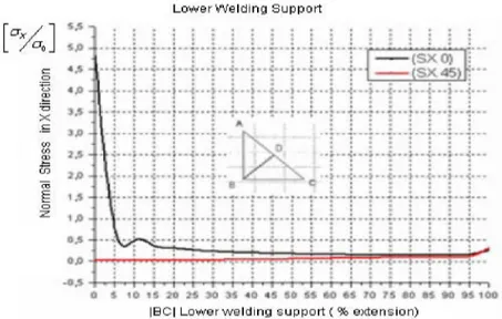
significantly; although in the other area, stress values do not change a lot. It is observed from Figure 17 that stress values obtained from the lower welding support are on the same level obtained at the values on welding neck. However, elongation amount per percent changes with the decreasing of temperature. Maximum stress on the lower welding support occurs in Y direction on the mouth angle of 150. On the other hand, equivalent stress at 00
mouth angle was higher than the lower support tip. As a result, T and corner welding with 450 welding mouth produced satisfactory results than the T
welding with 150 and 30° of welding mouth. A decreasing tendency of stress
values are seen in T welding models having 150, 300 and 450 mouth angles.
Preparation of 450 welding mouth has advantage comparing to other
Figure 15. |BD| welding neck of normal stress in X direction. U p p e r W e l d i n g S u p p o r t
|BA| U p p e r w e l d i n g s u p p o r t ( % e x t e n s i o n )
Figure 16. The variation of normal stress in X direction along the |BA| upper welding
support. L o w e r W e l d i n g S u p p o r t [ « s t i : : : ; : ; -0 1
x
* 1 to ? CO § o J o*A
— ¡ 3 X 0 ) -0 1x
* 1 to ? CO § o J o*A
u
" T T l — i f -- ( S X 45) -0 1x
* 1 to ? CO § o J o*A
u
" T T l — i f -0 1x
* 1 to ? CO § o J o*A
i : j A ; } ; I j ; -0 1x
* 1 to ? CO § o J o*A
V : A -0 1x
* 1 to ? CO § o J o*A
1 -A -0 1x
* 1 to ? CO § o J o*A
1 - -1" —-j— » : -0 1x
* 1 to ? CO § o J o*A
i
• : s : : -0 1x
* 1 to ? CO § o J o*A
-0 1x
* 1 to ? CO § o J o*A
j ' T : | S' : 0 4 i t I I i t i l H ]* to « «4 TO TJ «4 «4 » lOO ¡ B O | L o w e r w e l d i n g , s u p p o r t ( % e x t e n s i o n )Figure 17. The variation of normal stress in X direction along |BC| lower welding
4. CONCLUSION
From the angle of 0o to 45o, for the opening welding mouth in each 15o of
angle, only the values in the first and last degrees of angles were taken into consideration and the results were reported. The maximum stress value was so small and it occurred in almost in a point area and it showed a bigger decrease in a short distance. Stress value in welding root formed more than the stress in the upper foot tip and this was understood from the color scale. The big stresses can reduce the lower values within very small distance. Closing to the upper welding support, the stress welding values increased and this was expected situation. According to all results except shear stress, minimum stress values formed in the root of welding in case of opening a welding mouth of 450. Preparing a 450 of mouth, welding root is disappeared and structure
became permanent. The critical point of maximum stress values is the tip of upper support in 450 mouth angle.
R E F E R E N C E S
[1] Taljat B, Radhakrishnan B, Zacharia T. Numerical analysis of GTA welding process with emphasis on post-solidification phase transformation effects on the residual stresses. Mater Sci Engng A 1998;246:45-54.
[2] Chang KH, Lee CH, Residual stresses and fracture mechanics analysis of a crack in welds of high strength steels, Engineering Fracture Mechanics 74 (2007) 980-994
[3] Brickstad B, Josefson BLI, A parametric study of residual stresses in multi-pass butt-welded stainless steel pipes, International Journal of Pressure Vessels and Piping 75 (1998) 11-25
[4] Scammangas A, Porter Goff RFD, Residual stresses in cylinder girth butt welds, 7th Annual Offshore Technology Conference, Houston TX, USA, Paper 5024, 1985.
[5] Josefson BL. Residual stresses and cracking susceptibility in butt-welded stainless steel pipes. In: Morgan E, Lewis R, editors. Numerical methods in thermal problems, Part 2. Swansea, UK: Pineridge Press, 1985:1152-67.
[6] Josefson BL, Karlsson CT FE-calculated stresses in a multi-pass buttwelded pipe-a simplified approach. International Journal of Pressure Vessels and Piping, 1989;38:227-243.
[7] Gordon JR, Wang Y-Y, Michaleris P. Applying fitness-fomr-service to welded structures: special considerations for welded joints. In: Fitness-for-service and decisions for Petroleum and chemicaI equipment, ASME Publication PVP, Vol. 315. New York: American Society for Mechanical Engineers. 1995: 313-26.
[8] ASME Section XI Task Group for piping flaw evaluation Pressure vessel and piping codes. ASME Journal of Pressure Vessel Technology, 1986;108:352-366.
[9] Nichols RW. The use of overstressing techniques to reduce risk of subsequent brittle fracture. IIW Doc. X; 1997. p. 409-67.
[10] Radaj D. Heat effects of welding. Temporary field, residual stress, distortion. Berlin: Springer; 1992. p. 292-303.
[11] Se^dek P, Gotkowski P, Bro'zda J. Application of numerical methods to mechanical prestressing of pressure vessels. Proceedings of the Fifth International Conference Computer Technology in Welding, Paris, France, 15-16.06.1994, Cambridge: The Welding Institute;1994.
[12] Soy, U., Caliskan, M., Findik, F., Cagdak, F., "Analysis of T-Weld Performance of IPGT 200 Steel Profiles with Computer Modeling", Proceedings of the International Conference on Computational and Mathematical Methods in Science and Engineering, CMMSE-2005, Page:516-525, ISBN No: 84-609-4844-7, Alicante, SPAIN, 27-30 June, 2005.
[13] H. Deren, Steel Constructions, Istanbul Technical University, ITU Press, Istanbul, 1995
[14] M. Karaduman, Steel Structures, Volume 1, Edition 4, Atlas Publishing House, Istanbul, September, 2002.
[15] S. Anik, Handbook of Welding Technology, Birsen Publishing House, Istanbul, 1981.
[16] S. Fricke, E. Keim, J. Schmidt, Numerical weld modelling — a method for calculating weld-induced residual stresses, Nuclear Engineering and Design 206 (2001) 139-150
[17] Scott D. Raymond, Peter M. Wild, Christopher J. Bayley, On modelling of the weld line in finite element analyses of tailor-welded blank forming operations, Journal of Materials Processing Technology 147 (2004) 28-37
[18] Jinmiao Zhang, Pingsha Dong , Frederick W. Brust, William J. Shack , Michael E. Mayfield , Michael McNeil, Modelling of weld residual stresses in core shroud structures, Nuclear Engineering and Design 195 (2000) 171-187 ,[19] Shahram Sarkani, Vesselin Tritchkov, George Michaelov, An Efficient approach for computing residual stresses in welded joints, Finite Elements in Analysis and Design 35 (2000) 247}268
[20] S.T. Lie , C.K. Lee, S.M. Wong, modelling and mesh generation of weld profile in tubular Y-joint, Journal of Constructional Steel Research 57 (2001) 547-567
[21] H. L. J. Pang, Analysis of weld toe profiles and weld toe cracks, International Journal of Fatigue , Volume 15, Issue 1 , January 1993, Pages 31-36
[22] Simon K. Clubley , Stuart S.J. Moy , Robert Y. Xiao, Shear strength of steel-concrete-steel composite panels. Part I-testing and numerical modelling, Journal of Constructional Steel Research 59 (2003) 781-794