MEMBRANE FUNCTION AS INTERIOR WALL TO CONTROL THE
DYNAMIC RESPONSE OF TANKS
Amir Shojaee
Department of Civil Engineering, Urmia University, Iran [email protected]
Changiz Gheyratmand
Department of Civil Engineering, Urmia University, Iran [email protected]
ABSTRACT
Sloshing represents a low-frequency fluctuations of the fluid in the half-full tank which if not controlled effectively, could be as one of the most important factors of destruction and reversal of tanks. Thus, study of the behavior of liquid storage tanks and providing new ways to reduce sloshing and to improve seismic response of tanks, due to the high costs of construction, has considerable importance. In this paper, the ability to control sloshing and demand reduction in external solid walls in two parts using two different methods have been investigated. In the first part, analysis are done in ANSYS finite element software and their accuracy are examined. In the second part, possibility of using membrane wall to improve performance of fluid-structure interaction system in tanks, by studying the behavior and performance of a tank with membrane wall in a manner similar to that mentioned in the first part, is studied. In this case, adjustment of fluid dynamics and structure has been done by tuning the tensile force applied to the membrane and the mass of the membrane, and system response has been compared with rigid tank state to evaluate the effects of applying membrane wall.
Keywords: Liquid Storage Tanks, Fluid-Structure Interaction, Sloshing, Frequency-Domain,
Membrane Wall
İÇ DUVAR GİBİ MEMBRAN İŞLEVİ TANKLARI DINAMIK CEVABI
KONTROL İÇİN
ÖZ
Sloshing etkin bir şekilde kontrol değilse, yıkım ve tankların bozma en önemli faktörlerden biri olarak olabilir yarı dolu tankın içindeki sıvı düşük frekanslı dalgalanmaları temsil eder. Böylece, sıvı depolama tankları davranışının çalışması ve inşaat nedeniyle maliyetlerinin yüksek, etrafa sıçramasını azaltmak ve tankların sismik tepki geliştirmek için yeni yollar sağlayan önemli bir öneme sahiptir. Bu yazıda, iki farklı yöntem kullanılarak iki parçaya dış katı duvarlar etrafa sıçramasını ve talep azaltımına kontrol edebilme incelenmiştir. Birinci bölümde, analiz ANSYS sonlu elemanlar yazılımı yapılır ve bunların doğruluğu incelenmiştir. İkinci bölümde, birinci bölümünde açıklanan benzer bir şekilde, membran duvar ile bir tank davranış ve performansı inceleyerek, tanklarda akışkan yapı etkileşim sisteminin performansını artırmak için membran duvar kullanma olasılığı, ele alınmıştır. Bu durumda, akışkan dinamiği ve yapısı ayarlama membran ve membran kütlesine uygulanan gerilme kuvveti ayarlayarak yapılmıştır ve sistem yanıt membran duvarı uygulanması etkilerini değerlendirmek için sert tankı devlet ile karşılaştırılmıştır.
Anahtar Kelimeler: Sıvı Depolama Tankları, Akışkan-Yapı Etkileşimi, sloshing, Frekans Domain,
INTRODUCTION
Traditionally, tanks have been essential to human for storage of required materials. One of the most important and most commonly used types of these tanks, is ground concrete tank. The usage of this tank is rather related to storage of water for consumption throughout the year and especially during emergencies such as natural disasters like floods, storms and most importantly earthquake. Now to secure these kinds of structures against earthquake, we require knowledge of how and type of earthquake effects on them so that they can be resistant against this natural and very great disaster. This study examines the effects of earthquake on ground concrete tank as well as the interaction of water inside it on the tank structure during the earthquake. To investigate these effects, a powerful finite element software called ANSYS has been used which has tremendous capabilities in modeling and analysis of the tank with considering the interaction effects of water on the tank. In the next stage MATLAB software is used for more detailed analysis and then these results are compared.
Sloshing indicates low frequency oscillations of free surface of fluid in the half-full tank. When the liquid mass is extremely high compared to the tank mass, sloshing could disturb the stability of the tank. This is mostly due to the creation of dynamic forces and changing the location of the center of mass. Summary of background studies indicate extensive use of system finite element modeling in the control of liquid sloshing in the formable tanks in the case of two-dimensional.
TANK MODELING AND USE OF MEMBRANE
EXPRESSING FINITE ELEMENT MODEL AND PROBLEM ASSUMPTIONS
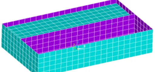
In this section, ANSYS v.11 finite element software is employed for modeling and analyzing of tank and water. The material of intended tank in numerical model is of concrete. This tank is cube-shaped and its upper surface is considered open. The length, width and height of tank are respectively 20, 12 and 5 meters. The thickness of tank walls is considered as 0.4 meter. The tank is filled to a height of 4 meters of water. A steel plate with thickness of 0.003 meter is placed in the middle, along the length of the tank. Water inside the tank is in contact with these steel plates which are dragged by the tensile force T. Specifications of used materials in the finite element model are listed in Table 2.1. Attenuation in all cases is considered zero for all materials.
Concrete tanks and steel plates is modeled using Shell63 two-dimensional shell element. Fluid80 cube three-dimensional element is also used for water modeling. Likewise, interaction effects of water and structure is achieved by coupling the displacement of water ties with displacement of tank ties and steel plate in the direction perpendicular to the surface of walls. So, water is surrounded by walls and steel plates.
Table 2.1 Specifications of used materials in the finite element model
Kind of material Modulus of elasticity (Gpa)
Poisson's ratio Density (kg/m3)
concrete 20 0.27 2450
steel 210 0.3 7850
water 2.1 0.0 1000
Modeling and analyzing is to determine the history of the displacement at several points in the tank and water. The purpose of using steel plate is to control the sloshing of water inside the tank and to reduce fluctuations of water in order to reduce the incoming force from water to tank. The finite element model of tank and water is shown in Figure 2.1.
To create waves a base excitation in accordance with the Kobe earthquake is inserted into the bottom of the tank. The kind of this excitation is of displacement and its details will be discussed later. Kobe earthquake, like all the other earthquakes possesses registered accelerogram. All of these accelerograms and the displacement history of this earthquake is extracted from the website and used. In Table 2.2 earthquake data and characteristics of accelerogram recording station, KJMA, is listed. Fig 2.2 has shown acceleration curve of this earthquake based on time. Figure 2.3 also shows the displacement history of the earthquake based on time. This information is recorded in accelerogram station of KJMA.
Table 2.2 Earthquake data and accelerogram recording station, KJMA
Earthquake Kobe, Japan
Date and time of the earthquake 20:46, 1995/16/01
Earthquake intensity 6.9 M
Earthquake hypocenter specifications
Longitude: 135,0121 Latitude: 34,5948 Hypocenter of the earthquake: 17.9 Km
Station name JMA99999KJMA
Specifications of recording station
Longitude: 135,1800 Latitude: 34,6833 Distance from the epicenter: 18.27 Distance from the hypocenter: 28.58 Maximum ground acceleration recorded at the station 0.821 g
Maximum ground speed recorded at the station 81.3 cm/s Maximum ground motion recorded at the station 17.68 cm
Fig 2.2 Diagram of earthquake accelerogram recorded in the KJMA station
Fig 2.3 Diagram for displacement history of Kobe earthquake recorded in the KJMA station
The base relocation excitation is used in the model to create wavy water inside the tank according to Fig 2.3. It should be noted that any analysis is done in 120 seconds. First 60 seconds undertake to reach the tank and water from the initial state to a stable state without excitation with system, after the first 60 seconds, accordance with the Kobe earthquake the base relocation excitation is applied to the system in the direction shown in Fig 2.1 and then, system continues to move without external excitation.
THE RESULTS OF ANSYS
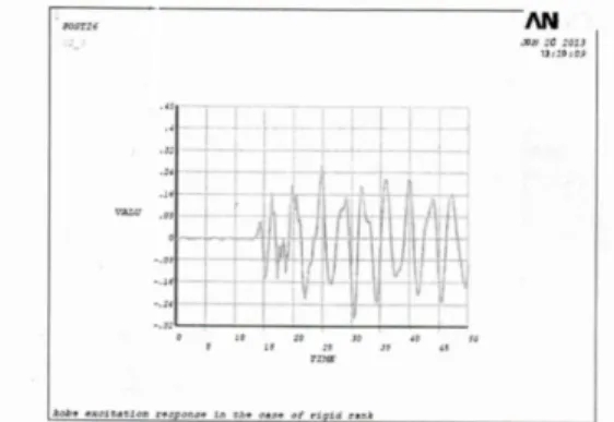
By analyzing the model by applying the Kobe earthquake with the abovementioned specifications, the following results are obtained (Fig 2.4) and when tank becomes rigid with increasing T and wall thickness, the resolution is as follows (Fig 2.5):
Fig 2.4 Diagram for vertical displacement history of rigid tank monitoring under the Kobe earthquake
Fig 2.5 Diagram for vertical displacement history of rigid tank monitoring under the Kobe earthquake ACHIEVING THE FORMULA AND SOLVING BY MATLAB
ACHIEVING EQUATIONS AND GOVERNOR BOUNDARY CONDITIONS
With assumptions:
1- Non-compressible flow 2- Non-viscous flow 3- Non-rotational flow
And with respect to satisfying the basic laws of fluid mechanics (stability of mass and momentum), we define a potential function:
Potential function
SOLVATION OF FREQUENCY-DOMAIN AND GOVERNOR FORMULATION EXTRACTION IN THE CASE OF USING FLEXIBLE MEMBRANE TO REDUCE PRESSURE ON THE TANK WALL
In this issue the tank is containing incompressible fluid which there is a flexible membrane in the middle of it.
THE EQUATION GOVERNING THE FLUID INSIDE THE TANK
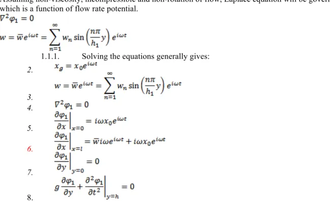
Assuming non-viscosity, incompressible and non-rotation of flow, Laplace equation will be governing which is a function of flow rate potential.
1.1.1. Solving the equations generally gives:
2. 3. 4. 5. 6. 7. 8.
After extracting the equations governing the tanks and solving them using computational software MATLAB, the system response can be achieved with applying different seismic excitations. After extracting primary results, it can be seen that conversion function approach to infinity in system natural frequencies which as a result, by multiplying the values of conversion function of each frequency at the amplitude proportional to that frequency and inversing the Fourier transform to obtain time history response, the correct answer is not achieved. According to the results of time history also it is evident that the first condition of rest is not satisfied at the beginning of excitation. To address this problem, the slight attenuation is applied to the conversion function which in this case because of zero wave elevation in the first instance, acceptable results are obtained.
Since the potential functions existed in the formulation are contained series, so it is necessary to carry out the convergence analyses to determine the number of terms in a series. Undertaking analysis by increasing the number of terms in series shows that the first term has the main role in the system response and ensures proper accuracy of response and increasing the number of terms has little effect on responses.
NUMERICAL RESULTS
SPECIFICATIONS OF SEISMIC EXCITATIONS
Applied excitations are in the term of sinusoidal displacements with amplitude of 0.1 m and with periods in the range of 2.4 s to 12 s. Also, applied earthquake includes 090 component of Kobe earthquake in 1995 recorded at Nishi – Akashi station. Properties of applied earthquake are proposed in Table 3.1.
Existence of flexible membrane wall provides the ability to change the dynamic characteristics of tank by changing the rate of membrane tensile force and the mass of the membrane wall. Thus in order to change the mass of the membrane wall, the ratio of mass change is multiplied at density per unit length of the wall.
Table 3.1 Specifications of applied earthquakes to tank with membrane wall
Record of earthquake / Date of occurrence Component Duration (sec) Epicenter (km) Hypocenter (km) Maximum acceleration Kobe/1995 NIS090 40 8.7 17.9 0.305
Given the frequency contents of earthquake records, the earthquake is classified in the category of near-field earthquakes which has a relatively similar frequency to spectral peaks at low periods. Near-field earthquakes occur in less time but exert larger acceleration to the structure than far-Near-field earthquakes.
ASSESSING TANK RESPONSE UNDER HARMONIC EXCITATIONS
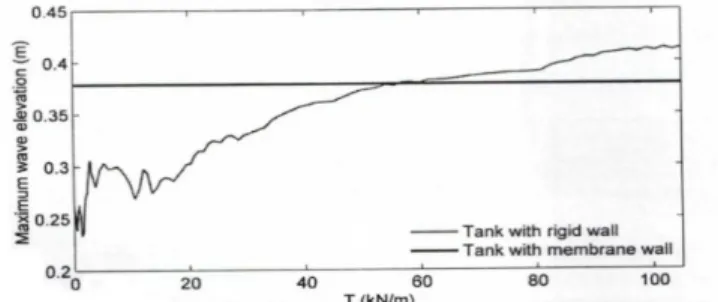
Changing the rate of membrane tensile force by changing the dynamic specifications of liquid-tank system, influences the system response to the seismic excitations. According to Figure 3.5, diagramming the maximum change of wave elevation with change of membrane tensile force, under the influence of harmonic excitation with a frequency of 3.6 seconds (approximately equal to the natural frequency of the rigid tank) shows that for relatively wide range of T, significant reduction arises in the maximum wave elevation. Tuning the mass of the membrane is also effective in reducing the response of wave elevation. In Figure 3.6, change of maximum wave elevation with change of CM ratio for a membrane tank with T=1100 kN/m under the influence of harmonic excitation with a frequency of 3.6 seconds has been shown.
Fig 3.5 Change of maximum height of sloshing in tank with membrane wall with change of
membrane tensile force
Fig 3.6 Change of maximum height of sloshing in tank with membrane wall with change of the mass
of the membrane
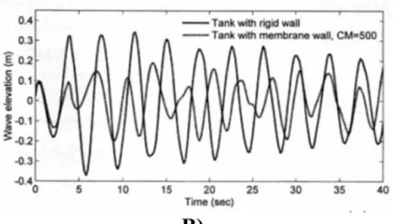
Time history of wave elevation on the edge of the rigid wall of the tank, for the membrane tank with T=1100 kN/m and for different values of CM, under the influence of harmonic excitation with period of 3.6 seconds has been shown in Figure 3.7. Provided diagrams show that employing membrane wall reduces the maximum wave elevation so that tuning the rate of mass increases the rate of created decline.
B)
Fig 3.7 Time history of sloshing height under the influence of sinusoidal excitation in comparison to
rigid tank response; A) CM=1 B) CM=500
Figure 3.8 shows the change of maximum wave elevation as a result of excitation frequency change and compares with rigid tank. As can be seen for the tank with membrane wall, the period corresponding to the maximum response has changed than to the amount corresponding to rigid tank and has shifted towards more periods. In addition, the maximum response is dropped. Controlling the amount of mass also creates a greater reduction in the maximum response so that for CM=500 a significant reduction occur in the maximum wave elevation compared to the corresponding amount in the rigid tank.
Fig 3.8 Changing the maximum height of sloshing in the tank with membrane wall by changing the
period of ground displacement
RESPONSE OF TANK TO THE KOBE EARTHQUAKES
Due to the frequency content of ground displacement in this earthquake, it can be seen that Kobe earthquake is classified in the category of near-field earthquakes which have relatively similar frequency content to the spectral peaks at low periods. Therefore, it is expected the case tank to show similar performance against these two earthquakes. In Figures 3.9 to 3.13 numerical results and diagrams related to membrane tank has been proposed.
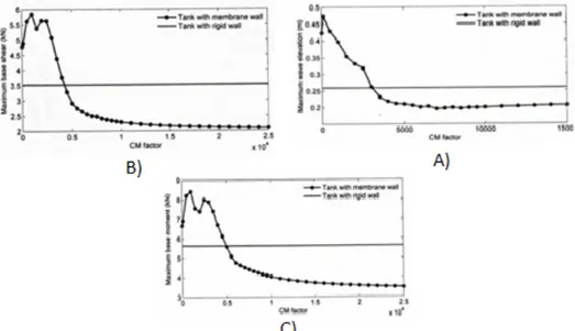
Fig 3.9 Changing the maximum modulus response of membrane tank by changing CM coefficient
under the influence of Kobe earthquake; A) Height of sloshing B) basic cutting C) basic moment According to the above diagrams, CM = 10000 is selected as the optimal membrane mass. A summary of the percent of reduction created in the maximum values of responses in the optimal state is provided in Table 3.2.
Table 3.2 A summary of the results obtained for a membrane tank under the influence of Kobe
earthquake
Crated reduction compared with Response Value of CM corresponding to the
minimum amplitude of response
Response of rigid tank (%) Response of membrane tank with CM=1 (%) Amplitude of sloshing 10000 23 53 Basic cutting of outer wall 10000 35 52 Basic moment of outer wall 10000 28 40
Fig 3.10 Time history of wave elevation in the membrane tank with CM=10000 under the influence
Fig 3.11 Fourier transform of free vibration response of wave elevation for membrane tank with
CM=10000
Fig 3.12 Fourier transform of wave elevation response for membrane tank with CM=10000 under the
influence of Kobe earthquake
Referring to the displacement response spectra and acceleration of Kobe earthquake record which is provided in Fig 3.13, change in the values of responses also can be investigated by changing the system natural period. By definition, response spectra of an excitation in a particular period, is equal to the maximum response of a system with one degree of freedom and the same natural period. It can be seen that changing the natural period of the system is associated with reduction in acceleration response amplitude and displacement.
Fig 3.13 Response spectra of Kobe earthquake COMPARE OF RESPONSE TO DIFFERENT SEISMIC EXCITATIONS
Using membrane wall and tuning its mass is effective to control responses under the influence of near-field earthquakes. To justify the reason of reduction in structural responses, the behavior of membrane tank with CM=10000 is considered under the influence of harmonic excitations which the optimal mass ratio is Kobe earthquake. According to Figure 3.14 it can be seen that use of flexible middle wall with adjusted mass leads to reduce the amplitude of maximum wave elevation in smaller periods and growth of it in larger periods.
Fig 3.14 Change of maximum height of sloshing in the membrane tank by changing of the period of
excitation
RESULTS FOR RIGID TANK
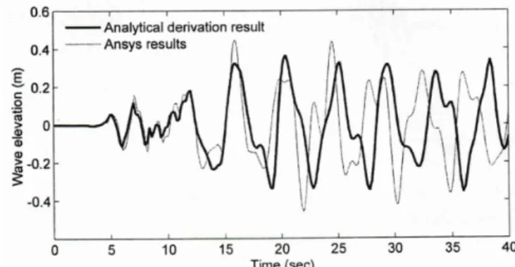
Figure 3.15 shows the time history of vertical displacement of monitoring tie of rigid tank under the influence of Kobe earthquake. Figure 3.16 also represents the conformity of this diagram with time history diagram of wave elevation for rigid tank under the influence of Kobe earthquake. Proper adaptation of resulted diagrams from ANSYS with obtained diagram from employed analytical approach confirm both the accuracy of analytical solution and acquired results. Slight difference in results is because of the difference in how to apply damping using ANSYS and analytical solution.
Fig 3.15 Diagram of vertical displacement history of rigid tank monitoring under Kobe earthquake
Fig 3.16 Comparison diagram of vertical displacement history of rigid tank monitoring tie under the
influence of Kobe earthquake
RESULTS FOR RIGID TANK WITH A MIDDLE MEMBRANE WALL
Figure 3.17 depicts time history of vertical displacement of monitoring tie for the rigid tank with a middle membrane wall under the influence of Kobe earthquake. Figure 3.18 also demonstrates the adaptation of this diagram with time history diagram of wave elevation for the rigid tank with a middle membrane wall under the influence of Kobe earthquake. Proper adaptation of resulted diagrams from ANSYS with obtained diagram from employed analytical approach in chapter 4 confirm both the accuracy of analytical solution and acquired results. Slight difference in results is because of the difference in how to apply damping using ANSYS and applied analytical solution.
Fig 3.17 Diagram of vertical displacement history of monitoring tie for the rigid tank with a middle
membrane wall under the influence of Kobe earthquake
Fig 3.18 Comparison diagram of vertical displacement history of monitoring tie for the rigid tank with
a middle membrane wall under the influence of Kobe earthquake
RESULTS
Response of rigid rectangular tank with membrane wall in the frequency domain obtained and then response history acquired using Fourier inverse conversion. Studies showed that obtained results from employed analytical approach perfectly match with the acquired results from modelling and analyzing in the finite element software of ANSYS and the results presented in the literature which confirms the accuracy of applied analytical solution. Effects of membrane wall on the natural frequencies of system were considered. The results showed that the use of membrane wall instead of rigid wall alters the natural frequencies of vibration of liquid-tank system and the mass of membrane wall is a factor to change the dynamic characteristics of the system. It was shown that it is possible to reduce response under the influence of harmonic excitations with different frequencies and tuning the mass of membrane wall under the frequency equal to the frequency of fluid vibration in the rigid tank, leads to response reduction in a wide range of excitation frequency. Fluid and tank dynamic adjusted by changing and tuning the mass of the membrane wall such that the reduction of structural responses and sloshing height would be possible. According to the results, it was shown that membrane wall of tanks can be used as mass absorbent to control and reduce fluid vibrations or forces acting on other walls of tanks and employing membrane wall which its mass is not tuned and in other words the value of coefficient (CM) equals to 1 and instead of rigid wall, leads to a significant reduction in the maximum values of cutting absolute and the moment of the base of the outer wall and maximum height of sloshing. Also with regarding the results, the mass range which reduces the value of responses and the percentage of created reduction under the influence of various earthquakes are different and are dependent to frequency content of earthquake and its type; far-field or near-field earthquake. Using mass absorbent as the membrane wall, is more effective in the control of system response under the near-field earthquakes. The reason for this is justified by comparing the frequency content of earthquakes. Since in this approach, natural frequencies of the system change and the natural period of the system moves to the higher periods and since in the near-field earthquakes the frequency domain of earthquake approaches zero in higher periods, so this leads significant reduction of responses under the influence of such earthquakes. Usually membrane wall is designed as rigid and regardless of being membrane and this makes it can be ignored the positive or negative effects of the
membrane walls on other walls (rigid walls). If the mass of these walls is not tuned, usually increases the sloshing of water or cutting and moment of rigid walls. Thus ignoring the walls being membrane is non-conservative. On the other hand, by increasing the mass and tuning its value, the walls can be used as mass absorbent and creates a significant reduction in the height of sloshing or cutting and moment of rigid walls. Also in the other control methods of sloshing, usually it is not possible to reduce and control the sloshing and structural forces at the same time. Therefore, it can be said that reduction of maximum height of sloshing and maximum cutting and moment of the base of the outer wall is one of the most prominent positive aspects of employing membrane walls.
ACKNOWLEDGEMENT
Thanks to the efforts of dear masters which in every phase of this article have guided me with high patience and tolerance.
REFERENCES
[1] Anderson, J. G., 2009, Liquid Sloshing in Containers, Its Utilization and Control .
[2] Anderson, J. G., Semercigil, S. E. and Turan, Ö. F., 2010a, A Standing-Wave Type Sloshing Absorber to Control Transient Oscillations, Journal of Sound and Vibration, 232(5), pp. 839-856 . [3] Anderson, J. G., Semercigil, S. E. and Turan, Ö. F., 2008b, An Improved Standing-Wave Type Sloshing Absorber, Journal of Sound and Vibration, 235(4), pp. 702-710 .
[4] Anderson, J. G., Semercigil, S. E. and Turan, Ö. F., 2012, Comparison of a Sloshing Absorber and Tuned Absorber for Optimal Vibration Control, Proceedings of the Australasian Conference on Structural Optimisation, Sydney, Australia, pp. 199-206 .
[5] ANSYS , 2011, User Manual, ANSYS Inc .
[6] Bauer, H. F. and Chiba, M., 2010, Axisymetric Oscillation of a Viscous Liquid Covered by an Elastic Structure, Journal of Sound and Vibration, 281 (2009), pp. 835-847 .
[7] Chen, W. and Haroun, M. A., 2009, Dynamic Coupling Between Flexible Tanks and Seismically Induced Nonlinear Liquid Sloshing, Fluid Transients ASME,FED- Vol. 198IPVP
- Vol.29 1 .
[8] Fotia, G., Massida, L. and Siddi, G., 2012, Computational Modelling of Sloshing in Flexible Tanks, CRS4-Waves & Structures, Tech. Rep 00 .
[9] Fujino, Y., Sun, L. M, Pacheco, B. M. and Chaiseri P., 2010, Tuned Liquid Damper (TLD) for Suppressing Horizontal Motion of Structure, Journal of Engineering Mechanics, Vol. 1 18, No.1 0, pp.263-272 .
[10] Gradinscak, M. Semercigil, S. E. and Turan, Ö. F., 2012, Sloshing Control with Container Flexibility, 14th Australasian Fluid Mechanics Conference, Adelaide University, Adelaide, Australia . [11] Gradinscak, M., Semercigil, S. E. and Turan, Ö. F., 2012, Design of Flexible Containers for Sloshing Control, Proceedings of ASME FEDSM'02, ASME 2002 Fluids Engineering Division Summer Meeting, Montreal, Quebec, Canada .
[12] Gradinscak, M., Guzel, U. B, Semercigil, S. E. and Turan, Ö. F., 2009, Control of Liquid Sloshing in Flexible Containers: Part 2. Added Mass, 15th Australasian Fluid Mechanics Conference, University of Sydney, Sydney, Australia .
[13] Gradinscak, M. Semercigil, S. E. and Turan, Ö. F., 2012, Liquid Sloshing in Flexible Containers, Part 1: Tuning Container Flexibility for Sloshing Control, Fift International conference on CFD in the Process Industries, CSIRO, Melbourne, Australia, 13-15 December .
[14] Gradinscak, M. Semercigil, S. E. and Turan, Ö. F., 2012, Liquid Sloshing in Flexible Containers, Part2: Using a Sloshing Absorber With a Flexible Container for Structural Control, Fift International conference on CFD in the Process Industries, CSIRO, Melbourne, Australia, 1315 December .
[15] Guzel, U. B, Gradinscak, M., Semercigil, S. E. and Turan, Ö. F., 2010, Control of Liquid Sloshing in Flexible Containers: Part 1. Added Mass, 15th Australasian Fluid Mechanics Conference, University of Sydney, Sydney, Australia .
[16] Guzel, U. B, Gradinscak, M., Semercigil, S. E. and Turau, Ö. F., 2009, Tuning Flexible Containers for Sloshing Control, Proceedings of the IMAC-XXIII: A Conference & Exposition on Structural Dynamics, January 31-February 3, Orlando, Florida.