A HOMOGENEOUS SYSTEM FOR PHOTOGENERATION OF
HYDROGEN INITIATED BY BODIPY BASED
PHOTOINDUCED ELECTRON TRANSFER
A THESIS SUBMITTED TO
THE GRADUATE SCHOOL OF ENGINEERING AND SCIENCE OF BILKENT UNIVERSITY
IN PARTIAL FULFILLMENT OF THE REQUIREMENTS FOR THE DEGREE OF MASTER OF SCIENCE IN CHEMISTRY By HALE ATILGAN August, 2015
i
A HOMOGENEOUS SYSTEM FOR PHOTOGENERATION OF HYDROGEN INITIATED BY BODIPY BASED PHOTOINDUCED ELECTRON TRANSFER By Hale Atılgan
August, 2015
We certify that we have read this thesis and that in our opinion it is fully adequate, in scope and in quality, as a thesis for the degree of Master of Science.
_______________________
Prof. Dr. Engin Umut Akkaya (Advisor)
_______________________ Assoc. Prof. Dr. Dönüş Tuncel
_______________________
Assist. Prof. Dr. Fazlı Sözmen
Approved for the Graduate School of Engineering and Science: _______________________
Prof. Dr. Levent Onural Director of the Graduate School
ii
ABSTRACT
A HOMOGENEOUS SYSTEM FOR PHOTOGENERATION OF HYDROGEN INITIATED BY BODIPY BASED PHOTOINDUCED ELECTRON TRANSFER
Hale Atılgan
M.S. in Department of Chemistry Supervisor: Prof. Dr. Engin Umut Akkaya
August, 2015
The key technology to fulfill the energy needs in the future is the generation of fuels by harvesting solar energy. Due to high abundance and low prices of cobalt, water-splitting (based on cobalt) method has received a lot of attention compared to noble metals. Several times cobaltoxime based catalysts were studied for proton reduction. In this project, our aim was to produce a homogeneous photocatalytic system for photogeneration of hydrogen with high efficiency. To do so, we synthesized ten integrated molecules in which we are making use of the highly quantum efficient and photostable BODIPY chromophore. After the synthesis and characterization of target molecules, we achieved to demonstrate hydrogen evolution with five of our molecules.
Keywords: Photocatalysis, water splitting, hydrogen generation, BODIPY, photoinduced electron transfer
iii
ÖZET
BODIPY TABANLI FOTOİNDÜKLEMELİ ELEKTRON TRANSFERİ SİSTEMLERİ ARACILIĞIYLA HOMOJEN HİDROJEN FOTOJENERASYONU
Hale Atılgan
Kimya Bölümü, Yüksek Lisans
Tez Yöneticisi: Prof. Dr. Engin Umut Akkaya Ağustos, 2015
Güneş enerjisinin toplanmasıyla yakıtların üretilmesi, geleceğin enerji ihtiyacını karşılayacak bir teknolojidir. Kobalt, soy metallere gore, yerkürede daha çok miktarda bulunduğundan ve daha ucuz olduğundan dolayı suyun parçalanması metodunda sıkça kullanılmaktadır. Proton indirgenmesinde bir çok kez kobaltoksim katalistleri kullanılmıştır.
Bu projede, homojen bir fotokatalitik system oluşturularak hidrojen fotojenerasyonunun yüksek verlimlilikle sağlanması amaçlanmaktadır. Bunu yapmak için, yüksek kuantum verimliliğine ve fotostabiliteye sahip BODIPY boyaları kullanılarak on molekül sentezlenmiştir. Hedeflenen moleküllerin sentezi ve karakterizasyonundan sonra, moleküllerin beş tanesi hidrojen üretmiştir.
Anahtar Kelimeler: Fotokataliz, suyun parçalanması, hidrojen üretimi, BODIPY, fotoindüklemeli elektron transferi
iv
v
Acknowledgement
Foremost, I would like to express my sincere thanks to my research supervisor Prof. Dr. Engin U. Akkaya for the continuous support of my master studies and research, for his patience, motivation, enthusiasm, and immense knowledge. Excellent two years of my life has passed under his guidance in his group where I have met the most beautiful friends in my life. I will never forget the experiences that I have benefited from him throughout my life. I could not have imagined having a better advisor and mentor for my master studies.
I would like to gratefully acknowledge my Thesis Committee Members, Assoc. Prof. Dr. Dönüş Tuncel and Assist. Prof. Dr. Fazlı Sözmen for their encouraging and fruitful discussions and advices.
I place on record, my since thank you to Prof. Dr. Walter Weare for the hydrogen generation measurements.
I also would like to thank Dr. İlke Şimşek Turan and Deniz Yılmaz for her contribution to the projects that we worked on together.
My biggest thanks must be given to my close friends Tuğçe Durgut, Ceren Çamur, Melek Baydar Baytak, Darika Okeeva, Tuğçe Karataş, Cansu Kaya, Dielse Inroga, Mu’azzam Idris and Hidayet Baytak for all the fun times we have had together in and out of the lab. I will truly miss them very much.
I would like to thank former and present group members of the Akkaya group Dr. Tuğba Özdemir Kütük, Dr. Safacan Kölemen, Dr. Ruslan Guliyev, Dr. Fazlı Sözmen, Dr. Murat Işık, Dr. Onur Büyükçakır, Dr. Esra Eçik Tanrıverdi, Yiğit Altay, Bilal Uyar, Ahmet Atılgan, Nisa Yeşilgül, Bilal Kılıç, Dr. Dilek Taşgın, Dr. Özlem Seven, Seylan Ayan, Veli Polat and the rest of EUA lab for creating a great environment in which to work and for their valuable input to my projects. I had wonderful people around me.
vi
In particular, and in no particular order, thank you my dear friends, Büşra Kamiloğlu, Gürkan Gök, Ramazan Güllüce and Yunus Can Esmeroğlu for invaluable friendship and wonderful memories we had together. Even Ankara could be a great city to live in with these people.
I would like to thank my mother Şehirli Atılgan and father Ahmet Atılgan. I am always proud of being their daughter. Your consultant love, support and guidance made me who I am today. My amazing brother, Halil Atılgan, thank you very much for supporting all my crazy ideas for all the time. I cannot imagine being the person I am today without such a great brother through the years. Thanks for everything that helped me get to this day.
Last but not least, I want to express my gratitude to my fianceé, José Luis Bila for his endless love, support, kindness, understanding and of course patience for the past almost seven years. No words can explain how much I love him. The best thing in our relationship is that we have seen each other grown up. I hope you will always be with me, baby.
vii
LIST OF ABBREVIATIONS
AcOH : Acetic Acid
BODIPY : Boradiazaindacene
CHCl3 : Chloroform
ER : Electron Relay
Et3N : Triethylamine
HOMO : Highest Occupied Molecular Orbital
LUMO : Lowest Unoccupied Molecular Orbital
MS : Mass Spectroscopy
NMR : Nuclear Magnetic Resonance
PS : Photosensitizer
SC : Sacrificial Reagent
TEOA : Triethanolamine
TFA : Trifluoroacetic Acid
THF : Tetrahydrofuran
TLC : Thin Layer Chromotography
TON : Turn Over Number
WOC : Water Oxidation Catalyst
viii
TABLE OF CONTENTS
1. INTRODUCTION ... 1 2. BACKGROUND INFORMATION ... 3 2.1. Energy Resources ... 3 2.1.1. Solar Energy ... 3 2.1.2. Wind Energy ... 3 2.1.3. Hydropower ... 4 2.1.4. Biomass Energy ... 4 2.1.5. Geothermal Energy ... 4 2.1.6. Hydrogen ... 42.2. Energy Related Global Problems and Hydrogen as an Energy Carrier 5 2.3. Hydrogen as the Solution to the Present Problems ... 7
2.4. Hydrogen Production Technologies ... 8
2.5. Solar Water Splitting to Hydrogen and Oxygen ... 9
2.5.1. Mechanism of Water Splitting Reaction ... 11
2.5.2. Applications of Water Splitting Reaction ... 12
2.6. Photocatalytic Systems for H2 Generation ... 14
2.6.1. Photosensitizer ... 14
2.6.2. Electron Relay ... 15
2.6.3. Sacrificial Reagent ... 16
2.6.4. Catalyst ... 17
2.7. BODIPY Dyes ... 19
2.7.1. Synthesis of BODIPY Dyes ... 22
2.7.2. Applications of BODIPY Dyes ... 24
3. EXPERIMENTAL ... 27
3.1. General ... 27
3.1.1. Synthesis of Compound (23) ... 28
3.1.2. Synthesis of Compound (24) ... 28
ix 3.1.4. Synthesis of Compound (26) ... 30 3.1.5. Synthesis of Compound (27) ... 30 3.1.6. Synthesis of Compound (28) ... 31 3.1.7. Synthesis of Compound (29) ... 32 3.1.8. Synthesis of Compound (30) ... 33 3.1.9. Synthesis of Compound (31) ... 33 3.1.10. Synthesis of Compound (32) ... 34 3.1.11. Synthesis of Compound (33) ... 35 3.1.12. Synthesis of Compound (34) ... 36 3.1.13. Synthesis of Compound (35) ... 37 3.1.14. Synthesis of Compound (36) ... 38 3.1.15. Synthesis of Compound (37) ... 39 3.1.16. Synthesis of Compound (38) ... 40 3.1.17. Synthesis of Compound (39) ... 40 3.1.18. Synthesis of Compound (40) ... 41 3.1.19. Synthesis of Compound (41) ... 42 3.1.20. Synthesis of Compound (42) ... 43 3.1.21. Synthesis of Compound (43) ... 44 3.1.22. Synthesis of Compound (44) ... 45 3.1.23. Synthesis of Compound (45) ... 45 3.1.24. Synthesis of Compound (46) ... 46 3.1.25. Synthesis of Compound (47) ... 47 3.1.26. Synthesis of Compound (48) ... 47 3.1.27. Synthesis of Compound (49) ... 48 3.1.28. Synthesis of Compound (50) ... 49
4. RESULTS AND DISCUSSIONS ... 51
5. CONCLUSION ... 64
BIBLIOGRAPHY ... 65
x
LIST OF FIGURES
Figure 1. (a) Hydrogen production sources currently used in the world. (b) The main hydrogen-consuming sectors in the world. Copyright © 2011 Wiley-VCH Verlag
GmbH & Co. KgaA. Reprinted with permission from ref (25). ... 6
Figure 2. Hydrogen supply options and usages [ ]. PV, photovoltaic cells; ICEs, internal combustion engines; IT, information technology; FCVs, fuel cell vehicles; ICEVs, internal-combustion-engined vehicles. Copyright ©2008, Royal Society of Chemistry, Reprinted with permission from ref (27). ... 7
Figure 3. Photosynthesis by green plants and photocatalytic water splitting (artificial photosynthesis). Copyright © 2008, Royal Society of Chemistry. Reprinted with permission from ref (40). ... 10
Figure 4. Water Splitting Mechanism. ... 12
Figure 5. Example of application of water splitting reaction in ion exchange acidic resin reported by Yamashita et al. Copyright © 2014, American Chemical Society. Reprinted with permission from ref (45). ... 13
Figure 6. Example of application of water splitting in semiductor catalyst presented by Brückner et al. Copyright © 2013 WILEY-VCH Verlag GmbH & Co. KGaA, Weinheim, Reprinted with permission from ref (47). ... 13
Figure 7. Lehn et al. Reported Ru(bpy)32+ complex used as a photosensitizer in a photocatalytic system. Copyright © 1979, Verlag GmbH & Co. KGaA, Weinheim. Reprinted with permission from ref (54). ... 14
Figure 8. Examples of photosensitizer which have no nobel metals in a photocatalytic systems for hydrogen generation reported by Eisenberg et al.4 ... 15
Figure 9. Methyl Viologen (MV2+) as an electron relay. ... 16
Figure 10. Example of an electron relay reported by Alberto et al.56 ... 16
Figure 11. Some examples of electron donors in a photocatalytic system.42 ... 17
Figure 12. Examples of macrocyclic Co catalysts used as water reduction catalysts. Copyright © 2012, Royal Society of Chemistry. Reprinted with permission from ref (44). ... 18
Figure 13. Photocatalysts reported by Eisenberg et al. which are used in a photocatalytic system. Copyright © 2012, Royal Society of Chemistry. Reprinted with permission from ref (44). ... 19
xi
Figure 15.Functionalization of 3,5 and 1,7 positions by Knoevenagel condensation reaction. Copyright © 2009, American Chemical Society. Reprinted with permission
from ref (73). ... 22
Figure 16. Synthetic pathways for meso-functionalized symmetric BODIPYs. ... 23
Figure 17. Synthetic pathways for meso-unsubstituted symmetric BODIPYs. ... 23
Figure 18. Some examples of BODIPY based photosensitizers used in photodynamic therapy. ... 24
Figure 19. Some examples of BODIPY based chemosensors. ... 25
Figure 20. Examples of light harvesting systems and energy transfer cassettes. ... 26
Figure 21.Synthesis of Compound (23). ... 28
Figure 22. Synthesis of Compound (24). ... 28
Figure 23. Synthesis of Compound (25). ... 29
Figure 24. Synthesis of Compound (26). ... 30
Figure 25. Synthesis of Compound (27). ... 30
Figure 26. Synthesis of Compound (28). ... 31
Figure 27. Synthesis of Compound (29). ... 32
Figure 28. Synthesis of Compound (30). ... 33
Figure 29. Synthesis of Compound (31). ... 33
Figure 30. Synthesis of Compound (32). ... 34
Figure 31. Synthesis of Compound (33). ... 35
Figure 32. Synthesis of Compound (34). ... 36
Figure 33. Synthesis of Compound (35). ... 37
Figure 34. Synthesis of Compound (36). ... 38
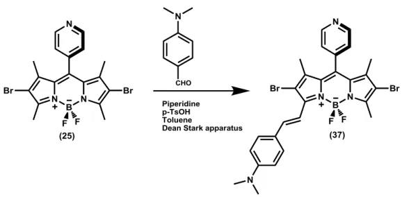
Figure 35. Synthesis of Compound (37). ... 39
Figure 36. Synthesis of Compound (38). ... 40
Figure 37. Synthesis of Compound (39). ... 40
Figure 38. Synthesis of Compound (40). ... 41
Figure 39. Synthesis of Compound (41). ... 42
Figure 40. Synthesis of Compound (42). ... 43
Figure 41. Synthesis of Compound (43). ... 44
xii
Figure 43. Synthesis of Compound (45). ... 45
Figure 44. Synthesis of Compound (46). ... 46
Figure 45. Synthesis of Compound (47). ... 47
Figure 46. Synthesis of Compound (48). ... 47
Figure 47. Synthesis of Compound (49). ... 48
Figure 48. Synthesis of Compound (50). ... 49
Figure 49. Water splitting mechanisms. Copyright © 2012, Royal Society of Chemistry. Reprinted with permission from ref (44). ... 52
Figure 50. Synthetic pathway for compounds 26, 28, 29. ... 55
Figure 51. Synthetic pathway for compounds 33, 36. ... 56
Figure 52. Synthetic pathway for compound 38. ... 57
Figure 53. Synthetic pathway for compounds 44 and 47... 58
Figure 54. Synthetic pathway for compound 41. ... 58
Figure 55. Synthetic pathway for compound 50. ... 59
Figure 56. Molecular structures of compounds 26 and 28 respectively. Copyright © 2014 American Chemical Society. Reprinted with permission from ref (106). ... 60
Figure 57. Molar extinction coefficients of compounds 33,36,38,41,44 and 47. ... 60
Figure 58. Hydrogen evolution profiles of compounds 26 (68) and 28 (65) irradiated at 525 nm at pH 7.7 in 7:3 acetonitrile/ water solution with 5% triethanolamine. ... 62
Figure 59. 1H spectrum of compound 24. ... 75
Figure 60. 13C spectrum of compound 24. ... 76
Figure 61.1H spectrum of compound 25. ... 77
Figure 62. 13C spectrum of compound 25. ... 78
Figure 63.1H spectrum of compound 26. ... 79
Figure 64. 1H spectrum of compound 27. ... 80
Figure 65. 13C spectrum of compound 27. ... 81
Figure 66. 1H spectrum of compound 28. ... 82
Figure 67. 1H spectrum of compound 29. ... 83
Figure 68. 13C spectrum of compound 29. ... 84
Figure 69. 1H spectrum of compound 30. ... 85
xiii
Figure 71. 1H spectrum of compound 31. ... 87
Figure 72. 13C spectrum of compound 31. ... 88
Figure 73. 1H spectrum of compound 32. ... 89
Figure 74. 13C spectrum of compound 32. ... 90
Figure 75. 1H spectrum of compound 33. ... 91
Figure 76. 1H spectrum of compound 34. ... 92
Figure 77. 13C spectrum of compound 34. ... 93
Figure 78. 1H spectrum of compound 35. ... 94
Figure 79. 13C spectrum of compound 35. ... 95
Figure 80. 1H spectrum of compound 36. ... 96
Figure 81. 1H spectrum of compound 37. ... 97
Figure 82. 13C spectrum of compound 37. ... 98
Figure 83. 1H spectrum of compound 39. ... 99
Figure 84. 13C spectrum of compound 39. ... 100
Figure 85. 1H spectrum of compound 40. ... 101
Figure 86. 13C spectrum of compound 40. ... 102
Figure 87. 1H spectrum of compound 42. ... 103
Figure 88. 13C spectrum of compound 42. ... 104
Figure 89. 1H spectrum of compound 43. ... 105
Figure 90. 13C spectrum of compound 43. ... 106
Figure 91. 1H spectrum of compound 45. ... 107
Figure 92. 13C spectrum of compound 45. ... 108
Figure 93. 1H spectrum of compound 46. ... 109
Figure 94. 13C spectrum of compound 46. ... 110
Figure 95. 1H spectrum of compound 48. ... 111
Figure 96. 13C spectrum of compound 48. ... 112
Figure 97. 1H spectrum of compound 49. ... 113
Figure 98. 13C spectrum of compound 49. ... 114
Figure 99. 1H spectrum of compound 50. ... 115
xiv
Figure 101. ESI-HRMS of compound 23. ... 118
Figure 102. ESI-HRMS of compound 24. ... 118
Figure 103. ESI-HRMS of compound 25. ... 119
Figure 104. ESI-HRMS of compound 26. ... 119
Figure 105. ESI-HRMS of compound 27. ... 120
Figure 106. ESI-HRMS of compound 28. ... 120
Figure 107. ESI-HRMS of compound 29. ... 121
Figure 108. ESI-HRMS of compound 30. ... 121
Figure 109. ESI-HRMS of compound 31. ... 122
Figure 110. ESI-HRMS of compound 32. ... 122
Figure 111. ESI-HRMS of compound 33. ... 123
Figure 112. ESI-HRMS of compound 34. ... 123
Figure 113. ESI-HRMS of compound 36. ... 124
Figure 114. ESI-HRMS of compound 37. ... 124
Figure 115. ESI-HRMS of compound 38. ... 125
Figure 116. ESI-HRMS of compound 39. ... 125
Figure 117. ESI-HRMS of compound 42. ... 126
Figure 118. ESI-HRMS of compound 43. ... 126
Figure 119. ESI-HRMS of compound 44. ... 127
Figure 120. ESI-HRMS of compound 45. ... 127
Figure 121. ESI-HRMS of compound 46. ... 128
Figure 122. ESI-HRMS of compound 47. ... 128
Figure 123. ESI-HRMS of compound 48. ... 129
Figure 124. ESI-HRMS of compound 49. ... 129
xv
LIST OF TABLES
1
CHAPTER 1
1. INTRODUCTION
In the beginning of 19th century, the need for fossil fuel consumption sharply increased following the industrial revolution in UK and only recently it was realized that the earth’s atmosphere is not an infinite sink for CO2 and other pollutants. In
near future, serious global catastrophic problems such as ozone hole and global warming will be faced. An additional 50% increase is expected in the global energy need for the year 2030.1 Due to the steep rise in energy demand as the global population increases, the decrease in fossil energy resources and environmental concerns of nuclear energy, there has been rapidly growing interest to search for renewable and clean energy resources.2 The most important energy source that has the potential to satisfy this demand is solar energy which emerges as a front-running clean, abundant and secure source. The conversion of solar energy into storable and easily transportable energy in the form of molecular hydrogen via the light induced water splitting is one of the most promising approaches toward the generation of green and renewable energy.3
The photochemical hydrogen generation through direct water splitting is a key transformation toward the conversion of solar energy into stored more sustainable fuels which does not emit greenhouse gases upon combustion.4 The photocatalytic hydrogen generation system has been designed to perform reductive side of water splitting-i.e., light induced conversion of aqueous protons into H2. For this, the
system has been established based on the effective coupling of light harvesting system with a sacrificial electron donor and a catalyst.5 Novel catalysts are still being developed to overcome thermodynamic and kinetic problems related to the water splitting reaction. These studies on catalyst development specifically focus on stopping the back oxidation reaction, separation of H2 and O2, production of
2
sacrificial water reductants for the removal of oxygen and the use of earth abundant elements. Although there is a great success, there is still need for the development of high quantum efficiency photo-absorbers that operate in the usable wavelength range, and two-photon efficient systems that have potential to enlarge this wavelength range.
In this work, our aim is to produce a new homogeneous photocatalytic system for the photogeneration of hydrogen with high efficiency using a highly absorbing photosensitizer and a cobalt complex as catalyst. To implement this goal, we are developing an integrated catalyst in which BODIPY has been employed as a chromophore due to its unique photophysical properties like high molar absoption coefficients, high quantum yields, narrow emission bandwidth with high peak intensities, great photostability and ease of functionalization.6,7 The photosensitizer has been functionalized accordingly with a cobalt complex which will serve as a reduction center, dimethylamino and pyridine functionalities which will act as oxidation center. Additionally, pH dependent regulation of hydrogen generation can be achieved via the modulation of the photoinduced electron transfer.
3
CHAPTER 2
2. BACKGROUND INFORMATION
2.1. Energy Resources
Many nations’ energy needs lean on coal, oil, and natural gas; however assurance of fossil fuels presents an important big problem. Fossil fuels are one of the finite resources. Sooner or later the world will run out of the fossil fuels, or their access will be very hard and expensive. Furthermore, fossil fuels are not environmentally friendly, they cause air, water, and soil pollution and also they evolve some greenhouse gases which contribute to global warming.8
There are many forms of renewable energy such as wind, solar and hydropower. These renewable resources offer alternatives to fossil fuels.9 In addition, they produce almost no pollution or greenhouse gases and they will have no end.
2.1.1. Solar Energy
The sun is our most powerful source of energy. Sunlight is free and infinitely renewable. Since it is not likely fossil fuels and nuclear power, this solar power gives no polluting emissions to the environment and it does not cause global warming.10 It has many more advantages. Solar panels work silently and they are easy to operate. What is more, their cost is also affordable. Because of the growing global demand, solar power has transposed to manufacturing. Utilities can also benefit from solar panels especially when the demand of electricity is high.
2.1.2. Wind Energy
Wind is the movement of air and the wind energy has been used for many years for sailing ships and drive windmills. In today’s world, this clean energy is used by wind
4
turbines and to generate electricity. The power of wind should be kept in mind as a long-term energy strategy because natural power sources are used for the generation of wind power. Its generation is clean and it does not cause any pollution.11
2.1.3. Hydropower
Hydropower is the energy produced by movement of water. Water is a renewable resource renewed by cyclization of evaporation and precipitation. Water evaporates from lakes and oceans by the help of the heat of sun and they form clouds. After, the water falls back to Earth as rain or snow, and goes to lakes and rivers. When the wind is caught by turbines and generators, that energy can be used to generate electricity.12
2.1.4. Biomass Energy
Biomass energy comes from plants such as crops, forest residues etc. and it is used to make biofuels and to generate heat and electricity. Biomass does not give any harmful sulfur or mercury emissions like coals. By the help of biofuels in cars or airplanes, one can contribute more against global warming pollution. However, it should be taken into account that biomass energy should not only reduce global warming pollution, but it should also protect the environment and should not cause the foods’ prices to increase.9
2.1.5. Geothermal Energy
Geothermal energy is the energy which comes from the reservoirs of hot water underneath of Earth’s surface. That hot water can be used to power generators and to generate electricity. It is also can be used for home heating systems. It is a clean, green and renewable resource and it produces almost no global warming pollution.13
2.1.6. Hydrogen
Hydrogen is an important, alternative clean energy carrier and it has a significant role in the reduction of emissions of greenhouse gases.14 Researches are based on to develop friendly, enviromentally and economical hydrogen generation technologies
5
which are essential for hydrogen economy.15 Hydrogen also does not exist but it should be generated from fuels or water and it is the most abundant element in the universe.16
2.2. Energy Related Global Problems and Hydrogen as an
Energy Carrier
During the recent years, most of the world’s energy requirements for transportation, heating, energy generation etc. are supplied from fossil fuels like petroleum, coal and natural gas.17 However; due to the increasing concerns over the depletion of fossil fuel supplies, global warming caused by greenhouse gases such as carbon dioxide, and enviromental pollution, there has been a much attention to the development of renewable resources which should be only long-term solution to this crucial problem of the world’s increasing population.18,19
In the recent years, many scientists and economists have seen hydrogen as a mean to solve all these problems caused by the usages of fossil fuels. To all appearances, it sounds simple such that: (i) hydrogen is one of the most plentiful elements on Earth, (ii) combustion of molecular hydrogen, H2, with oxygen produces heat and that molecular hydrogen and oxygen is used in
fuels to generate electricity, (iii) the only byproduct of the reaction of molecular hydrogen and oxygen is water, while the product of combustion of fossil fuels is carbon dioxide and some other pollutants, (iv) it is showed that hydrogen can be used in vehicles as an internal combustion engine. In consequence, if hydrogen could be used instead of fossil fuels, all the problems related to enviroment and global warming would be solved.20,21
Hydrogen is the most abundant element in the universe and is the third most abundant element on Earth’s surface.22,23
Hydrogen is very reactive; therefore, it is easily combined with any elements. Since it is present in water (H2O), it exists in
every living organism.24 In addition, it is present in hydrocarbons (e.g. methane), in organic compounds. Hydrogen is colorless, oderless and it can undergo combustion
6
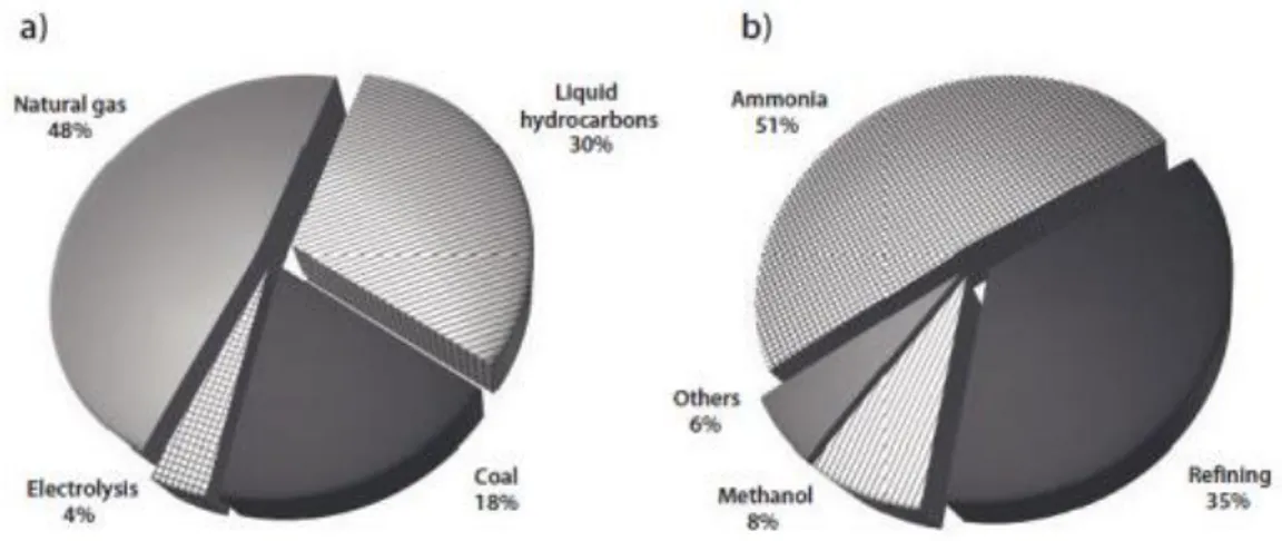
reaction with oxygen forming only water as a byproduct.8 Hydrogen gas is very light and it can diffuse easily and if it is not combined, it can escape from the atmosphere. In recent years, 95 % of hydrogen is generated from fossil fuels generating carbon dioxide. Hydrogen is also generated from electrolysis; however, it is not that used. Hydrogen is mainly used in the synthesis of ammonia and refining processes.25
Figure 1. (a) Hydrogen production sources currently used in the world. (b) The main hydrogen-consuming sectors in the world. Copyright © 2011 Wiley-VCH Verlag GmbH &
Co. KgaA. Reprinted with permission from ref (25).
However, since there is no molecular hydrogen on Earth, molecular hydrogen should be produced by using energy. In consequence, hydrogen can be seen as an energy carrier, not an alternative fuel.26 There are many ways to produce hydrogen either from renewable resources or nonrenewable resources, which is schematically summarized in Figure 2.27 As it is seen in Figure 2, hydrogen can be generated renewable resources such as wind, solar-thermal, biomass etc, from fossil fuels, natural gas, coal, and hydrogen also can be used to transfer energy to where it is used such as fuels cells, turbines etc.
7
Figure 2. Hydrogen supply options and usages [ ]. PV, photovoltaic cells; ICEs, internal combustion engines; IT, information technology; FCVs, fuel cell vehicles; ICEVs, internal-combustion-engined vehicles. Copyright ©2008, Royal Society of Chemistry, Reprinted with
permission from ref (27).
2.3. Hydrogen as the Solution to the Present Problems
Even though the element hydrogen is not found in its elemental pure form, it is considered the lightest most abundant element in the universe making up to 75% of the universe’s elemental mass.28 Most of the times it is found in the form of other compounds such as hydrocarbons and water which means that an extraction is required. In an experiment conducted by T. Von Honenhein in 1493 hydrogen gas was produced by mixing strong acids with metals. However, Henry Cavendish in 1766 was able to isolate hydrogen and consider it a gas for the first time. As for the name Hydrogen, it was given from greek hydro which meant water and genes or in other words, “creator”.8
The reason hydrogen is considered the future solution of the nowadays energy problems is that is an energy carrier, nontoxic and its combustion does not cause pollution or even greenhouse gases.29 In addition to these factors, hydrogen has high
8
energy content and there is no need for combustion. Useful energy from hydrogen can be provided by simple electrochemical conversion method and also from fossil fuels, nuclear power plants and renewable energy sources. This means that, as a fuel, it could be used in various fields as long as there are fossil fuels available and it could offer direct benefits in terms of reduced pollution and cleaner environment. Although hydrogen is a good energy carrier, various challenges about its production and storage and even transportation are present.30
Various methods have been implemented during the years such as: production through water electrolysis, thermochemical cycles, direct thermal decomposition of water, photolysis and biomass.31 Another issue raised in when it comes to hydrogen is the transportation problems. Because it has to be delivered to the end user is through pipelines and tanks making it difficult for the economy.32 One final issue with hydrogen is the storage. Hydrogen is the lightest element on earth with density 0.03, 0.06 and 0.07 kg/L at 350 atm, 700 atm and liquefied at 20 K respectively.33 Therefore, it is a big problem to store hydrogen in its liquid form. Several techniques can be used for storage with a high volumetric and gravimetric density: high pressure gas cylinders, liquid hydrogen in cryogenic tanks, absorbed on interstital sites in a host metal, complex compounds, metals and complexes together with water. 34
2.4. Hydrogen Production Technologies
Presently, hydrogen is used in chemical industry; however, in the following years it will become an important fuel for us. There are many hydrogen production technologies from both fossil and renewable resources, pyrolysis, and water.35 The U.S. light vehicle fleet is over 225 million, travelling over 7 billion miles a day, and it is consuming 8 million barrels of oil in a day.36,37 Although US is the 3rd largest oil producer in the world, imported petroleum is expected to rise 60 % by 2025.38 However, there has become an interest to improve new alternative fuels to supply people’s need after oil embargo in US.39
But there is something clear that uncertainty of the countries in the world nowadays is the result of the cost of the oil
9
to increase substantially in the past few years. Not only prices, but also the environmental problems is the another problems that we should deal with. According to the analysis done in the recent years show that pollutants are very high to damage people’s health.35
In addition, the vehicles are the reason for the increase in the amount of carbon dioxide, volatile organic compounds, and other greenhouse gases. To cope with all these problems, there should be done to alter the world’s energy supply and find cleaner and alternative fuels. There is much alternative energy such as methane, gasoline, biodiesel; however, different technologies are needed to use these energies. However, hydrogen can be generated from all of these feedstocks and recently there have been many technologies to produce hydrogen.
2.5. Solar Water Splitting to Hydrogen and Oxygen
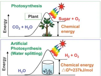
Hydrogen should be generated from water using natural sources such as sunlight (visible light) considering the enviromental issues. Hence, solar hydrogen production from water has been studied. There are some ways for solar hydrogen generation: (i) electrolysis of water using solar cell, (ii) reforming of biomass, (iii) water splitting photochemically or photoelectrochemically (artificial photosynthesis).40 As it is seen in Figure 3, in the photosynthesis reaction by green plants which is an uphill reaction, the photon energy is converted to chemical energy with a largely positive change in Gibbs free energy through water splitting.40 Hence, photocatalytic water splitting can be considered as an artificial photosynthesis and it is a very hot topic in chemistry.
10
Figure 3. Photosynthesis by green plants and photocatalytic water splitting (artificial photosynthesis). Copyright © 2008, Royal Society of Chemistry. Reprinted with permission
from ref (40).
Water splitting is the light driven of liquid water to gaseous hydrogen and oxygen as it is in the following:
H2O (l) sunlight H2 (g) + ½ O2(g) 41
At sea level, solar spectrum broadens from near infrared through the visible to near ultraviolet which is not absorbed by water itself. Therefore, some recyclable absorbing sensitizers are needed for photochemical reactions in order to absorb the light. These absorbing species have to be used to transduce the radiant energy to chemical energy in the form of electron holes pairs to drive the reaction.38 Secondly, sacrifical donors which are reduced materials are needed for water splitting. These donors should be oxidized more easily than water such as triethanolamine (TEOA), ethylenediamine tetraacetic acid (EDTA). Using of these kind of compounds develops the efficiency of the splitting process; however, sacrifical donors have better not be more expensive than the H2 produced for the practical systems. It is
better to use reduced waste materials for that purpose; however, it is more useful for large-scale fuel production.42
There are 2 electrons involve in the splitting reaction of water to hydrogen and oxygen, which is corresponding to 1.23 eV/e which is the standard emf of that
11
reaction. The energy of photons in the solar spectrum is sufficient enough to drive this reaction; however, the efficiency of the reaction depends on how the reaction is performed. The reaction can be performed thermally with light by the help of concentrators and a solar furnace by heating water to 1500-2500 K .43 However, at this point, the stability and cost of the capital equipment problems come out, and that decreases the reaction efficiency below 2 %. Therefore, this method is not a very good approach for solar water splitting.
There are some crucial properties for an efficient hydrogen evolution: (i) the sacrifical electron donor should be cheap and readily available; (ii) every intermediate charge relay has to be stable in the oxidized and the reduced states in order for the sensitizing dye to be multiple recycled; (iii) the oxidation of sensitizer should be faster than radiative and non-radiative relaxation of the excited state of sensitizer; (iv) durable catalyst must be effective in trapping the reduced relay for an efficient hydrogen evolution; (v) each component should be chemically and optically stable.42
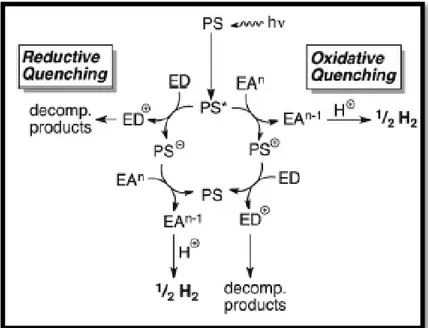
2.5.1. Mechanism of Water Splitting Reaction
The mechanism of the water splitting reaction is as seen in Figure 4, when photosensitizer (PS) or chromophore absorbs a photon, the excited PS* shows different properties than ground state PS. According to electron donor (ED), or electron acceptor (EA) groups, there occurs two electron transfer quenching pathways: reductive quenching and oxidative quenching respectively. In reductive quenching, the excited PS* is reduced to PS- by taking an electron from ED, then reducing PS- gives its electron to electron acceptor group which is H2 generating
catalyst. In the oxidative queching pathway, the excited PS* transfers its electron to electron acceptor group which can be either the catalyst in higher oxidation state or an electron transfer mediator such as methyl viologen. Then, oxidized PS+ takes an electron from ED to go to its intial from PS.44
12
Figure 4. Water Splitting Mechanism.
2.5.2. Applications of Water Splitting Reaction
There are numerous examples of water splitting reaction for hydrogen generation such as an ion exchange acidic resin, and semiconductor photocatalysts. To begin with, water splitting reaction can be used to create a noble-metal-free Ni-based catalyst for the hydrogen generation from water. As shown in Figure 5, Yamashita et al. presented a new catalyst created by a simple ion exchange of trinuclear complex, Ni(NiL2)2Cl2 (L= β-mercaptoethylamine) with a cation-exchange having strongly
acidic –SO32- groups. To effort the hydrogen production of Nicomplex/ resins, H2
production from water was carried under visible light irradiation in water solution containing triethanolamine (TEOA) as a sacrificial electron donor and Eosin Y as a photosensitizer. According to their experiments, Erythrosin B was found to be the best photosensitizer among rose Bengal and Eosin Y and pH = 7.5- 8.0 was the best pH value for H2 production. Moreover, it was also shown that this recovered catalyst
13
Figure 5. Example of application of water splitting reaction in ion exchange acidic resin reported by Yamashita et al. Copyright © 2014, American Chemical Society. Reprinted with
permission from ref (45).
Water splitting is used in semiconductor photocatalysts for hydrogen generation. As Fujishima and Honda suggested, photoelectrochemical evolution of H2 can be done
on TiO2 electrode by using water splitting reaction. When the electrons on valence
band are excited, they jump to the conduction band when the photons of energy equals to or greater than its band gap energy, and water is reduced and oxidized to hydrogen and oxygen gas respectively.46 Since TiO2 is only able to convert
high-energy UV light into chemical high-energy due to having high band gap high-energy, some thing should be done to shift the absorption edge of TiO2 into the visible range in the
spectrum. To do so, Brückner et al used surface coverage method by using gold nanoparticles (AU-NP) to shift its absorption edge to visible-light range. As it is seen in Figure 6, he observed the evolution of H2 under irradiation of Au-TiO2 catalyst
with visible light.47
Figure 6. Example of application of water splitting in semiductor catalyst presented by Brückner et al. Copyright © 2013 WILEY-VCH Verlag GmbH & Co. KGaA, Weinheim,
14
2.6. Photocatalytic Systems for H
2Generation
Photocatalytic systems for H2 generation mostly include a photosensitizer (PS), an
electron relay (ER), a sacrificial reagents (SR) or electron donor, and a water reduction catalyst (WRC).48–50 The total reaction is taken into account to be a visible-light-driven photon reduction by using an electron donor reagent to generate hydrogen via an electron relay.
2.6.1. Photosensitizer
The photosensitizer (PS) can be considered as the most important part of the whole system. Its function in the visible-light-driven systems for hydrogen generation is the absorption of visible light.51 Ruthenium complexes have a significant role in this field49, although a plethora of compounds based on other noble metals such as iridium52 and platinum.53 Nevertheless, there are still rare noble-metal-free photosensitizers. As Lehn et al. Reported, Ru(bpy)32+ is a very famous
photosensitizer used in a photocatalytic hydrogen production systems as it is seen in Figure 7.54
Figure 7. Lehn et al. Reported Ru(bpy)3 2+
complex used as a photosensitizer in a photocatalytic system. Copyright © 1979, Verlag GmbH & Co. KGaA, Weinheim. Reprinted
15
There are also more photosensitizer contaning no noble metals such as xanthene dyes Eosin Y (1), and Rose Bengal (2), which have been shown to catalyze visible-light-driven generation of H2 gas from aqueous protons as it is seen in Figure 8. 4
Figure 8. Examples of photosensitizer which have no nobel metals in a photocatalytic systems for hydrogen generation reported by Eisenberg et al.4
Eisenberg et al. have showed that while the parent fluorescein dye 4 shows no photocatalytic activity under the same conditions, the iodinated analogue 2 shows initial catalytic activity; however, it degrades faster than 1 under the same conditions. In addition, when the chlorinated dye 3 is used, the initial rates are reduced by a factor of 10.4
2.6.2. Electron Relay
In a photocatalytic water splitting reaction, the function of an electron relay is transfering the electron to proton which will be reduced to hydrogen. When the photosensitizer is excited, it transfers its electron to a molecule which acts as a relay to a proton source.55 In the literature, methyl viologen is one the best used electron relay in a photocatalytic system.48
16
Figure 9. Methyl Viologen (MV2+) as an electron relay.
Alberto et al. reported that ascorbate also acts as an electron relay in a photocatalytic system. They found that in the presence of [CoBr(aPPy)]Br catalyst, and electron donor tris-(2-carboxyethyl) phosphine (TCEP), production of hydrogen gas of the photosensitizer Ru(bpy)32+ is depending on the AscOH concentration.56
Figure 10. Example of an electron relay reported by Alberto et al.56
2.6.3. Sacrificial Reagent
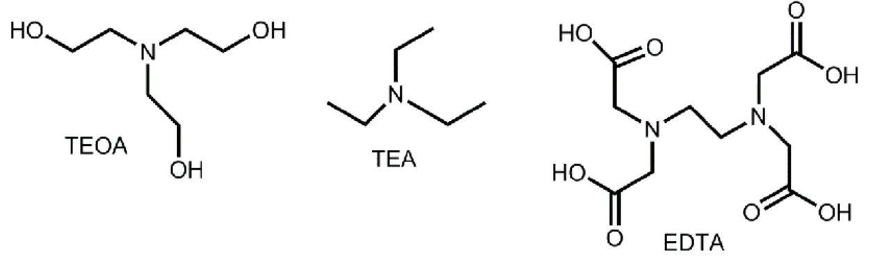
Sacrificial reagents or donors are used as reducing agents that are oxidized easier than water, for instance, ethylenediamine tetraacetic acid (EDTA), triethylamine (TEA), or triethanolamine (TEOA).42 These sacrifical donors provide electron refilling of the photosensitizer unit. Generally, when these donors are used in a solar process, the efficiency of the process is increased. According to Eisenberg et al., TEOA is proven to be the most effective electron donor at hydrogen evolution under same conditions compared to TEA and EDTA, showing more than 20-fold increase in activity.4
17
Figure 11. Some examples of electron donors in a photocatalytic system.42
2.6.4. Catalyst
The term “catalysis” was first used by Berzelius in 1836 to identify a new matter which has capability of popularizing the occurrence of a chemical reaction by a “catalytic contact”.57
According to him, a catalyst was a matter which acts as an accelerator for the speed of a chemical reaction when it is added to the reaction mixture. Catalysts had started to play a major role on chemical industry from the beginning of twentieth century, recently more than 95 % of chemicals are produced by a catalytic reaction.58
There are two types of catalysts; homogeneous catalysts and heterogeneous catalysts. In a heterogeneous reaction, the catalyst and the reactants are in different phase, whereas in a homogeneous reaction, the catalyst and the reactants are in the same phase. In literature, many homogeneous and heterogeneous catalysts made of noble metals such as ruthenium, iridium, and rhodium are developed. However, these noble metal made catalysts increase the cost. For water reduction, platinum has been used very often as a water reduction catalyst. Since platinum is very expensive and is low earth abundance, it should be replaced by a cheaper materials. Therefore, improvement of water oxidation catalysts (WOC) and water reduction catalysts (WRC) made of cheap and earth abundant elements is very crucial for solar energy conversion.59
In a photocatalytic system, function of a photocatalyst is to collect electrons for electrochemical potential and reduction of water and to serve as a gas evolution side,
18
meaning to produce H2 gas.60 The photocatalyst should have a suitable
thermodynamic potential for water splitting and a sufficient narrow band gap to harvest photons. It is supposed to be also stable against photocorrosion.58,61
There are many macrocyclic cobalt complexes used as water reduction catalysts for hydrogen generation as it is listed in Figure 12.44
Figure 12. Examples of macrocyclic Co catalysts used as water reduction catalysts. Copyright © 2012, Royal Society of Chemistry. Reprinted with permission from ref (44).
Eisenberg et al. showed that complex 5 has been found to produce H2 gas with 100
turnovers, while related difluoroborylated species 6 produces H2 gas in the presence
of strong acid as it is seen in Figure 13. Moreover, it was also shown that complex 5 was used for the first time to produce H2 from aqueous protons in a photocatalytic
19
Figure 13. Photocatalysts reported by Eisenberg et al. which are used in a photocatalytic system. Copyright © 2012, Royal Society of Chemistry. Reprinted with permission from ref
(44).
2.7. BODIPY Dyes
BODIPY (4,4-difluoro-4-bora-3a,4a-diaza-s-indacene) dye was synthesized for the first time unintentially in 1968 by Treibs and Kreuzer while they were trying to react 2,4-dimethylpyrrole with acetic anhydride in the presence of BF3.OEt2.62 After a very
long time Haugland and Kang reported the fluorescent properties of BODIPY dyes in 1985.63,64 After the discovering of characteristics of BODIPY dyes, its bio-labelling applications are employed intensively.65–67 In Figure 14, simple BODIPY core structure, and its IUPAC numbering are given.
Figure 14. The structure and numbering system of BODIPY.
For the last three decades, BODIPY dye has been used widely and it still is very popular. This popularity comes from its admirable properties of BODIPY. To begin with, the BODIPY unit has a major absorption peak corresponding to S0-S1 transition
-20
1
cm-1). It should be also taken into account that there is a weak peak at high-energy region around 370 ± 10 nm corresponding to S0-S2 transition.68 Due to the relaxation
of an excited electron from S1 state, strong and sharp emission is observed between
530-550 nm. BODIPY dyes have high thermal, photostability, physiological medium compatibility.69 They also have very high fluorescence quantum yield (f > 0.50) and
long fluorescence lifetimes. In BODIPY dyes, phosphorescence does not occur very often because these dyes have very low triplet quantum yields.69
Although BODIPY dyes have many advantages mentioned above, they also have some disadvantages such as solubility in aqueous solution. Moreover, they are lack of functional groups and low absorbance and emission wavelength for biomedical applications. However, these problems can be addressed by appropriate functionalization of the BODIPY core at meso (8), 1-7, 2-6, 3-5 positions and boron center.66,70 Functionalization of meso (8) position can be done with a suitable aldehyde or an acid chloride while performing the condensation reaction.71 When there is phenyl group at the meso position, the methyl groups at 1 and 7 positions of the BODIPY unit force phenyl group to be almost perpendicular to BODIPY core. In addition, meso position can be derived by the replacement of carbon atom with nitrogen atom, corresponding to aza-BODIPYs72 which shifts absorption and emission peaks to red end of the visible spectrum (650-850 nm).
Methyl groups at 1-7, and 3-5 positions have acidic character; hence, they are appropriate for Knoevenagel Condensation reaction.73 With the help of this condensation reaction, one can shift the absorption and emission peaks to the red side of the spectrum due to the extension of -conjugation as it is seen in Figure 15. As judged by Akkaya’s research group tetra-, tri-, di-, and monostyryl modifications have greater versatility.73 Several reasons have been attributed for this behavior such as the fact that Knoevenagel Condensation reaction has usually high yields in the case of 3-5 methyls; different aldehydes with different stereo-electronic characteristics can be used in different reaction conditions. Finally, in the case of strong charge donating groups, the molecules are likely to be used as switchable
21
molecules with internal charge transfer characteristics which can be used as chemosensors and molecular logic gates.74,75 Together with Knoevenagel Condensation reaction, when there are good leaving groups at 3 and 5 positions of BODIPY core, they are willing to nucleophillic aromatic substitution. As Dehaen and Boens reported, 3,5-dichloro BODIPY dyes are open to nucleophillic substitutions.76 In addition, in order to get photo-stable and redox active BODIPY derivatives, two fluorine atoms which are at the boron center can be replaced by alkoxides and aryl groups as it was reported by Ziessel et al., which are used as sensitizers for organic photovoltaics and dye-sensitized solar cells.77,78 2 and 6 positions of BODIPY core are relatively electron rich; therefore, they are open to electrophillic aromatic substitution. At these positions, one can perform some types of reactions such as, sulfonation79 which is important for water solubility, halogenation80 ,formylation81 , and nitration82 reactions. In addition to these reactions, some outstanding reactions can be done at these positions (e.g., Sonogashira, Suzuki, Stille reactions) when it is introduced heavy atoms such as iodine and bromine which quenches the fluorescence due to effective inter-system crossing.73
22
Figure 15.Functionalization of 3,5 and 1,7 positions by Knoevenagel condensation reaction. Copyright © 2009, American Chemical Society. Reprinted with permission from ref (73).
2.7.1. Synthesis of BODIPY Dyes
There are three different synthetic pathways to synthesize unsubstituted BODIPY dyes. First of all, according to Bruce et al.procedure83,84, once the formation of dipyrromethane, it is oxidized by DDQ to obtain dipyrromethene followed by the addition of tertiary amine base and BF3.OEt2. Secondly, Pene-Cabrera and
co-workers reported palladium-catalyzed reaction of 8-thiomethyl BODIPY and triethylsilane in the presence of copper(I) thienyl-2-carboxylate (CuTc) with very high yield[ ]. In the last synthetic pathway, in the presence of an acid, it occurs the condensation of unsubstituted pyrrole and pyrrole-2-carbaldehyde just before the addition of base and BF3.OEt2.83,85
Symmetric BODIPY dyes with meso derivatization are synthesized by acid-catalyzed condensation reaction of pyrroles with aldehydes, acid chlorides, or anhydrides in the presence of amine base and BF3.OEt270,86as it is seen in Figure 16. When one use
aldehydes in the condensation reactions, first of all dipyrromethane intermediate is formed, then it is oxidized to dipyrromethene by using quinone derivatives. Substituted BODIPY dyes at meso (8th position) position are very common in usage compared to unsubstituted BODIPY dyes due to their properties. For instance, they bring high stability, high solubility in organic solvents. In addition, they can be further functionalized depending on the end use.
23
Figure 16. Synthetic pathways for meso-functionalized symmetric BODIPYs.
One can also synthesize meso-unsubstituted symmetric BODIPY dyes by the condensation of excess pyrrole derivatives (~2.2 eq.) with orthoesters.83 In this kind of condensation reactions, first one obtain the dipyrromethene intermediate, then base and BF3.OEt2 complexation is added in order to obtain meso-unsubstituted
symmetric BODIPY dyes. According to Burgess and co-workers, meso-unsubstituted symmetric BODIPY dyes can be obtained by pyrrole-2-carbaldehyde and POCl3
without any excess pyrrole.87–89 Both pathways are given in Figure 17.
Figure 17. Synthetic pathways for meso-unsubstituted symmetric BODIPYs.
On the other hand, for synthesis of the asymmetric BODIPY dyes, condensation of pyrrole-2-carbaldehyde with other pyrrole derivatives can be used.90,91
24 2.7.2. Applications of BODIPY Dyes
There are many applications of BODIPY dyes due to the excellent properties of BODIPY dyes mentioned before. BODIPY derivatives can be used as fluorescent sensors, photosensitizers, photodynamic therapy agents. In addition, BODIPY dyes can be used in DNA labelling, light harvesting systems, molecular logic gates, ion sensing, liquid crystals, solar cells, energy transfer cassettes. Moreover, for the last years, BODIPY dyes have been used in photogeneration of hydrogen as photosensitizers.
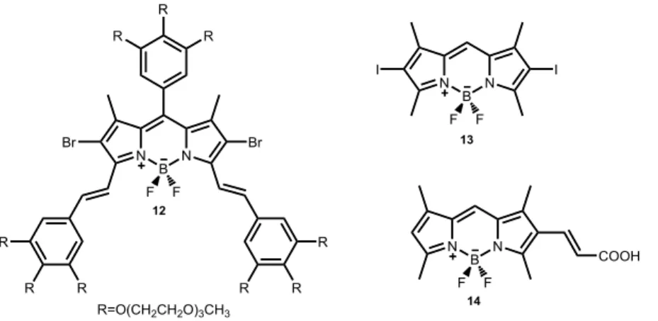
There are some BODIPY based sensitizers which are used in photodynamic therapy as it is seen in Figure 18. Compound 1292 which was reported by Akkaya et al is one example of water soluble BODIPY based sensitizer which is used in photodynamic therapy. One can get longer wavelength by increasing conjugation, and it can be increased intersystem crossing with the help of heavy atom (Br), which increases the yield of singlet oxygen generation. Compound 1393 which was introduced by Nagano et al having a very low quantum yield (0,02) due to heavy atom. Finally, compound 1494 can be considered as another water soluble BODIPY based sensitizer.
Figure 18. Some examples of BODIPY based photosensitizers used in photodynamic therapy.
Another applications of BODIPY dyes are PeT and ICT based sensors which can be seen in the Figure 19. Compound 1595 is a proton sensor. Strong electron donor dimethyl amino group promotes ICT. However; in the presence of a proton, dimethyl
25
amino group is protonated which blockes the ICT. Compound 1696 is used as a cadmium (II) sensor whose receptor part is anilino group. Compound 1797 has terpyridine group as recognition sites.
Figure 19. Some examples of BODIPY based chemosensors.
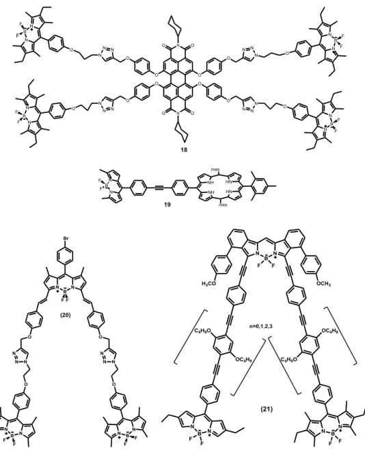
BODIPY dyes are also used in light harvesting systems and energy transfer cassettes. These systems consist of two parts which are donor and acceptor and there are two types of energy cassettes that are through space and through bond. In the Figure 20, compound 18 which was synthesized by Akkaya et al was designed for dendritic light harvesting systems.98 In this molecule, the acceptor part is perylene bisimide and donor part is BODIPY core. Compound 1999 is an example of energy transfer cassette through bond type. Compound 20100 is the example of space energy transfer array. Compound 21 is the example of two BODIPY units which have been linked together for a terminal acceptor BODIPY unit via aromatic linkers having various lenghts.101
26
27
CHAPTER 3
3. EXPERIMENTAL
3.1. General
All chemicals and solvents purchased from Aldrich were used without further purification. Column chromatography of all products was performed using Merck Silica Gel 60 (particle size: 0.040–0.063 mm, 230–400 mesh ASTM). Thin layer chromatography by Merck TLC Silica gel 60 F254 was used to monitor reactions. 1H NMR and 13C NMR spectra were recorded on Bruker DPX-400 (operating at 400 MHz for 1H NMR and 100 MHz for 13C NMR) in CDCl3 with tetramethylsilane as internal standard. All spectra were recorded at 25 oC and coupling constants (J values) are given in Hz. Chemical shifts are given in parts per million (ppm). Splittings in the spectra are shown as s (singlet), d (doublet), t (triplet), q (quartet), m (multiplet). Absorption spectrometry was performed using a Varian spectrophotometer. Fluorescence spectra were determined on a Varian Eclipse spectrofluorometer. All spectroscopy experiments were performed using spectrophotometric grade solvents. Mass spectroscopy measurements were conducted using MSBQTOF at Bilkent University, UNAM, Mass Spectrometry Facility.
28 3.1.1. Synthesis of Compound (23)
Figure 21.Synthesis of Compound (23).
After all the starting material was consumed, DMF was removed under high vacuum and the product was purified by silica gel chromatography. Since the solubility of the product was not good, its characterization was performed with mass spectrometry. ESI-HRMS (M-H+) calculated 358.97241, found 358.97682 Δ=-12.23ppm
3.1.2. Synthesis of Compound (24)
Figure 22. Synthesis of Compound (24).
To a 500 mL round-bottomed flask containing 250 mL argon-degassed dichloromethane, 2,4-dimethylpyrrole (2.11 mL, 20.54 mmol), 4-pyridine carboxyaldehyde (0.88 mL, 9.34 mmol) were added. Then, to the reaction mixture trifluoroacetic acid (888 µL) was added at dark and it was mixed for 1 day. Then, p-chloranil (1 g, 4.1 mmol) was added and mixed for 1 additional hour. After that, TEA (8 mL) was added and mixed for 1 additional hour and BF3.OEt2 (8 mL) was added
29
and the reaction mixture was left to stir at room temperature overnight. When the starting material was consumed, water (100 mL) was added and the reaction mixture was extracted into DCM (3x100 mL), evaporated. The residue was purified by silica gel column chromatography using EtOAc:DCM (1:1) as the eluant and the compound was obtained as orange solid (0.85 g, 28 %). 1H NMR (CDCl3, 400 MHz,
ppm) 7.08 (d, 2H, J=8.88 Hz ), 6.80 (d, 2H, J=8.76 Hz), 5.99 (s, 2H), 2.57(s, 6H), 1.51(s, 6H) . 13C NMR (CDCl3, 100 MHz, ppm) 156.5, 150.4, 143.7, 142.6 137.66,
123.3, 121.7, 14.7. ESI-HRMS (M-H+) calculated 323.15254, found 323.14983, Δ= 8.39 ppm
3.1.3. Synthesis of Compound (25)
Figure 23. Synthesis of Compound (25).
Compound (24) (100 mg, 0,307 mmol) was dissolved in 15 mL of DCM and 5 mL of DMF. Then, to the reaction mixture NBS (130 mg, 0.737 mmol) dissolved in 5 mL of DCM was added at room temperature. The progress of the reaction was monitored by TLC. After the starting material was consumed totally, water (100 mL) was added and the reaction mixture was extracted into DCM (3x100 mL), evaporated. The residue was purified by silica gel column chromatography using DCM as an eluant (0.142 g, 96 %). 1H NMR (CDCl3, 400 MHz, ppm) 8.83 (d, 2H, J=5.92 Hz ), 7.31
(d, 2HJ=5.70 Hz), 2.61(s, 6H), 1.39(s, 6H) . 13C NMR (CDCl3, 100 MHz, ppm)
150.6, 150.3, 145.9, 123.0 118.4, 99.9, 9.2, 9.0. ESI-HRMS (M+H+) calculated
30 3.1.4. Synthesis of Compound (26)
Figure 24. Synthesis of Compound (26).
Compound (23) (76.2 mg, 0.211 mmol) was dissolved in 15 mL of MeOH and TEA (29 µL, 0.212 mmol). After the solution turns brownish and fully dissolves, compound (25) (50 mg, 0.106 mmol) which was dissolved in 1 mL of CHCl3, and 40
mL of MeOH was added to the reaction mixture and the reaction was left to stir for 1 hour. When the starting material was consumed totally, the orange-red solids were filtered off, washed with methanol, and dried under vacuum (81mg, 48%). 1H NMR (CDCl3, 400 MHz, ppm) 8.53 (d, 2H, J=5.63 Hz ), 7.26 (d, 2HJ=5.55 Hz), 2.61(s,
6H), 2.46 (s, 12H) 1.16(s, 6H). ESI-HRMS (M-H+) calculated: 803.9844, found:
803.9823, Δ= 2.66 ppm
3.1.5. Synthesis of Compound (27)
31
Compound (24) (100 mg, 0.308 mmol) was dissolved in 20 mL of DCM and 10 mL of EtOH. Then, I2 (250 mg, 0.769 mmol) was added to the reaction mixture. HIO3
(108 mg, 0.615 mmol) was dissolved in minimum amount of water and added dropwise to the solution and the reaction mixture was heated under reflux at 50oC. When the starting material was consumed totally, saturated solution of Na2SO3 was
added and mixed for 20 min and the reaction mixture was extracted into DCM (3x100 mL), evaporated. The residue was purified by silica gel column chromatography using DCM as an eluant (130 mg, 75 %). 1H NMR (CDCl3, 400
MHz, ppm) 8.85 (d, 2H, J=5.11 Hz ), 7.31 (d, 2H J=5.81 Hz), 2.68 (s, 6H), 1.45(s, 6H). 13C NMR (CDCl3, 100 MHz, ppm) 157.8, 154.4, 150.8, 145.1 144.82, 124.3,
123.1, 17.2, 16.1. ESI-HRMS (M-H+) calculated 574.94583, found 574.94706, Δ= -2.15ppm
3.1.6. Synthesis of Compound (28)
Figure 26. Synthesis of Compound (28).
Compound (23) (62.5 mg, 0.173 mmol) was dissolved in 15 mL of MeOH and TEA (24 µL, 0.173 mmol). After the solution turns brownish and fully dissolves, compound (27) (50 mg, 0.087 mmol) which was dissolved in 1 mL of CHCl3, and 40
mL of MeOH was added to the reaction mixture and the reaction was left to stir for 1 hour. When the starting material was consumed totally, the reddish solids were filtered off, washed with methanol, and dried under vacuum. 1H NMR (CDCl3, 400
32
MHz, ppm) 8.52 (d, 2H, J=6.42 Hz ), 7.25 (d, 2H J=6.50 Hz), 2.65 (s, 6H), 2.46 (s, 12H), 1.18 (s, 6H). ESI-HRMS (M-H+) calculated 900.95, found 900.94763, Δ= -0.98 ppm
3.1.7. Synthesis of Compound (29)
Figure 27. Synthesis of Compound (29).
Compound (23) (113.7 mg, 0.315 mmol) was dissolved in 15 mL of MeOH and TEA (44 µL, 0.630 mmol). After the solution turns brownish and fully dissolves compound (24) (50 mg, 0.158 mmol) which was dissolved in 1 mL of CHCl3, and 40
mL of MeOH was added to the reaction mixture and the reaction was left to stir for 1 hour. When the starting material was consumed totally, the greenish solids were filtered off, washed with methanol, and dried under vacuum (0.098 g, 48 %). 1H NMR (CDCl3, 400 MHz, ppm) 8.43 (d, 2H, J=6.07 Hz ), 7.25 (d, 2HJ=6.06 Hz),
6.0 (s, 2H), 2.53 (s, 6H), 2.43 (s, 12H), 1.15(s, 6H) . 13C NMR (CDCl3, 100 MHz,
ppm) 157.6, 152.6, 151.8, 147.1, 141.3, 125.4, 122.4, 29.6, 14.1,13.0. ESI-HRMS (M-H+) calculated 648.16337, found 648.15960, Δ= 5.82 ppm
33 3.1.8. Synthesis of Compound (30)
Figure 28. Synthesis of Compound (30).
To a 500mL round-bottomed flask containing 500 mL argon-degassed dichloroethane, 2,4-dimethyl pyrrole (9.56 mmol, 0.924 g) and benzoyl chloride (4,34 mmol, 0.611 g) were added. The solution was refluxed for 1 day at 90oC. After that, 5 mL of Et3N and 5 mL of BF3.OEt2 were successively added and after 30 min,
the reaction mixture was washed with water (3 x 100 mL), which was then extracted into the CH2Cl2 (3 x 100 mL) and dried over anhydrous Na2SO4. The solvent was
evaporated and the residue was purified by silica gel column chromatography using 1:5 (EtOAc/Hexane)as the eluent.Red solid (0.631 g, 21%). 1H NMR (400 MHz, CDCl3) δ 7.50 – 7.46 (m, 3H), 7.29 (m, 2H), 6.00 (s, 2H), 2.58 (s, 6H), 1.39 (s, 6H). 13
C NMR (100 MHz, CDCl3) δ 131.8, 129.4, 129.1, 128.9, 128.2, 127.9, 119.8,
115.6, 15.1, 11.7. ESI-HRMS (M-H-) calculated 324.17184 found 324.17633, Δ= -13.64 ppm
3.1.9. Synthesis of Compound (31)
34
Compound (30) (100 mg, 0.308 mmol) was dissolved in 20 mL of DCM and 10 mL of EtOH. Then, I2 (196 mg, 0.771mmol) was added to the reaction mixture. HIO3
(109 mg, 0.617mmol) was dissolved in minimum amount of water and added dropwise to the solution and the reaction mixture was heated under reflux at 50oC for an hour. When the starting material was consumed totally, saturated solution of Na2SO3 was added and mixed for 20 min at room temperature and the reaction
mixture was extracted into DCM (3x100 mL), evaporated. The residue was purified by silica gel column chromatography using DCM as an eluant. HA 52 (100 mg, 0.308 mmol) was dissolved in 20 mL of DCM and 10 mL of EtOH. Then, I2 (250
mg, 0.769 mmol) was added to the reaction mixture. HIO3 (108 mg, 0.615 mmol)
was dissolved in minimum amount of water and added dropwise to the solution and the reaction mixture was heated under reflux at 50oC. When the starting material was consumed totally, saturated solution of Na2SO3 was added and mixed for 20 min and
the reaction mixture was extracted into DCM (3x100 mL), evaporated. The residue was purified by silica gel column chromatography using DCM as an eluant. (130 mg, 73 %). 1H NMR (400 MHz, CDCl3) δ 7.53 (s, 3H), 7.26 (s, 2H), 2.65 (s, 6H), 1.39 (s,
6H). 13C NMR (100 MHz, CDCl3) δ 156.7, 145.3, 142.4, 134.7, 129.5, 129.4, 127.8,
29.6, 16.9, 15.9. ESI-HRMS (M-H-) calculated 573.95058 found 573.94237, Δ= 14.3
ppm
3.1.10. Synthesis of Compound (32)
35
Compound (31) (177 mg, 0.307 mmol) and 4-pyridine carboxyaldehyde (72 µL, 0.710mmol) were added to a 100 mL round-bottomed flask containing 50 mL benzene and to this solution, piperidine (270 µL, 2.73 mmol) and acetic acid (220 µL, 3.84 mmol) were added. The mixture was heated under reflux at 100 oC overnight by using a Dean Stark trap and it is monitored by TLC. When all the starting material had been consumed, the mixture was cooled to room temperature and the solvent was evaporated. Water (100 mL) was added to the residue and the product was extracted with the DCM (3 x100 mL). The organic phace dried over Na2SO4, evaporated. The residue was purified by silica gel column chromatography
using 92:8 (EtOAc: MeOH) solution as the eluant and the compound was obtained as blue solid (0.065 g, %28 yield). 1H NMR (400 MHz, CDCl3) δ 8.70 (d, J= 5.8 Hz, 4H), 8.09 (d, J = 16.7 Hz, 2H), 7.86 (d, J = 16.7 Hz, 2H), 7.60-7.58 (m, 3H), 7.54 (d, J = 5.8 Hz, 4H), 7.34-7.32 (m, 2H), 1.50 (s, 6H). 13C NMR (100 MHz, CDCl3) δ 149.9, 147.1, 144.1, 136.5, 129.9, 129.7, 127.9, 123.0, 121.6, 17.6. ESI-HRMS (M-H-) calculated 752.00367 found 751.99281, Δ= 14.3 ppm
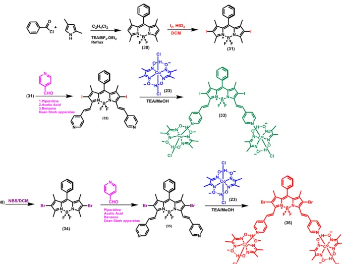
3.1.11. Synthesis of Compound (33)
![Figure 2. Hydrogen supply options and usages [ ]. PV, photovoltaic cells; ICEs, internal combustion engines; IT, information technology; FCVs, fuel cell vehicles; ICEVs, internal-combustion-engined vehicles](https://thumb-eu.123doks.com/thumbv2/9libnet/5783909.117472/23.893.283.656.150.478/hydrogen-photovoltaic-internal-combustion-information-technology-vehicles-combustion.webp)