IEEE JOURNAL OF SOLID-STATE CIRCUITS, VOL. 25, NO. 2, APRIL 1990 505
Design and Implementation
of a
General-Purpose Median Filter
Unit in CMOS
VLSI
Abstract -A general-purpose median filter unit configuration is pro- posed in the form of two single-chip median filters, one extensible and one real-time. The networks of the chips are pipelined and systolic at bit level and based on the udd/even transposition sorting. The chips are imple- mented in 3-pm standard CMOS by using full-custom VLSI design techniques. The exact median of elements, in a window size w = 9 with arbitrary word length L , can be found by using only one extensible median filter chip. The filter can be extended to arbitrary window sue and word lengths by using many chips. For w > 9 with arbitrary L , the number of chips required to find the exact medians is no more than the smallest greater integer of (w/9)*. Simulation results show that the extensible median filter chip can be clocked up to 40 MHz, and generate 30/L megamedians per second. On the other hand, the real-time median filter chip can find the exact running medians of elements in a window of a fixed sue w = 9 with L = 8. According to simulations, it can generate up to 50 megamedians per second with a 5 0 - a clock. The chips can be used for the realization of various median filtering techniques. In this paper, the algorithms, VLSI implementations, and testing of the chips are presented together with some possible applications.
I. INTRODUCTION
N MANY signal and image processing applications, it
I
is necessary to smooth the noisy signals while at the same time preserving the edge information. The most commonly used smoothing techniques . are linear filtering [l], averaging filtering [2], and median filtering [3]. The linear filters smooth the noisy signals but also the sharp edges. In addition, the impulsive noise components cannot be suppressed sufficiently by linear filtering, and digital implementation of the linear filters can be bulky and slow. The averaging filters have some undesirable features like outlier points that distort the filtered signal, and edge information loss. The median filters have proved to be good alternatives because they have some very interesting properties: 1) they can smooth the transient changes in signal intensity (e.g., noise); 2) they are very effective for removing the impulsive noises from the signals; 3) they can Manuscript received October 21, 1988; revised October 3, 1989. This work was supported in part by NATO’s Scientific Affairs Division in the framework of the Science for Stability Programme.The authors are with the Department of Electrical and Electronics Engineering, Bilkent University, 06572 Maltepe, Ankara, Turkey.
IEEE Log Number 8933646.
preserve the edge information in the filtered signal; and 4)
they can be implemented by using very simple digital nonlinear operations. Because of these properties of the median filters, they are frequently used in various signal and image processing applications, such as seismic signal processing, speech processing, computerized tomography, medical imaging, robotic vision, pattern recognition, peak detection, coding, and communication.
The median of a group, containing an odd number of elements, is defined as the middle element, when the elements of the group are sorted. A median filter finds the median of a number of elements at its input. In the standard median filtering applications, a window of size w , where w is odd, is moved along the sampled values of the signal or the image. For each position of the window, the median of the elements within the window is computed and then written as the output pixel located at the same position as the central element of the window. The median computed at this operation is called the running or the
moving median. Since the size of the window is constant,
the number of incoming elements is equal to the number of outgoing elements.
Detailed discussions of the theoretical analysis of the median filters and their properties can be found in [4]-[7]. The applications of the median filters in speech processing and in image processing were studied in [8]-[lo]. Various median filtering techniques were presented in [11]-[17]. The median filtering was first proposed by Tukey in 1974 [3]; since that time, there have been various studies to develop fast off-line and on-line algorithms, especially for software implementation [18]-[23]. Most of the median filtering algorithms for hardware implementation are based on sorting [24]-[26].
It is possible to design high-performance hardware me- dian filters by using the recent VLSI techniques. A good algorithm for VLSI implementation does not necessarily require the minimal computation but should possess the following properties [27]: the algorithm 1) can be imple- mented by using only a few simple units, 2) must have a simple and regular communication and control scheme, and 3) should employ parallelism and pipelining. A class
of algorithms that have these properties is called the sys- 0018-9200/90/0400-0505$01.00 01990 IEEE
506 IEEE JOURNAL OF SOLID-STATE CIRCUITS, VOL. 25. NO. 2, APRIL 1990
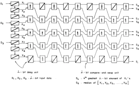
I- bit delay unit DI , D p , D3 . L - b i t input doto
L
- blt compare -and-swop unitS , kth greatest L - blt element of X , ‘ s
Fig. 1. Ordinary odd/even transposition sorting network for w = 9
tolic algorithms. These algorithms for various computa- tional problems have been discussed in [28]-[30].
Different two-dimensional applications require different window sizes and word lengths for median filtering. The window size varies from 3 X 3 to quite larger ones. Also the required speed of the filtering operation varies depending on the application. A median filter which is intended as a component of a general-purpose signal or image processor must meet these changing demands. Therefore such a filter must be 1) capable of operating at different word lengths, 2) extensible to larger window sizes, and 3) able to operate at a real-time rate whch is about 30 megamedians per second for 1024x1024 frames with 25-30 frames per second. We propose a solution to t h s problem in the form of two single-chip median filter networks that are imple- mented using the full-custom VLSI design techniques. Both of the networks are bit-level, systolic, and pipelined odd/even transposition sorting networks that employ all advantages of the systolic algorithms and satisfy the listed constraints for a general-purpose median filter. The net- works serve different purposes: one of them is designed for unlimited word length and extensibility to larger window sizes, and the other one is for real-time applications.
In the next section, first the ordinary odd/even transpo- sition sorting network is summarized. Then, the networks of the extensible and the real-time median filter chips are described. Section I11 covers the VLSI feasibility of the networks, their implementations, and testing of the chips. Some possible applications of the chps are discussed in Section IV. Finally, the results and conclusions of t h s study are presented in Section V.
11. THE ALGORITHMS
A . The Odd/Euen Transposition Sorting Network
The odd/even transposition sorting network presented
in [24] is a pipelined modular structure consisting of w
compare-and-swap stages. A compare-and-swap stage has ( w - 1)/2 full-word (L-bit) parallel compare-and-swap units and an L-bit delay unit to delay the window element whch is not compared at that stage. Each compare-and- swap unit operates on the odd and euen pairs of the window elements alternately (Fig. 1). Odd pairs are in the form of X,, and X,,,, where n is odd, whereas n is even for even pairs. Each full-word compare-and-swap unit compares two L-bit elements at its inputs and interchanges them if necessary so that the larger element will be at the ‘‘top” and the smaller one will be at the “bottom” output. At the output of the last stage, the input elements will be sorted such that the largest will be at the ‘‘top” and the median will be in the middle.
If the odd/even transposition network described above is implemented in hardware as a single-chip median filter for a fixed window size w,, then one cannot use that chip to find the exact medians of a window element whose size is larger than w,. Also, there is no flexibility on the word length because the compare-and-swap unit can be imple- mented only for a fixed word length in this configuration. Furthermore, the compare-and-swap unit can complete its job after an L-bit comparison resulting in a large propaga- tion delay. Although the throughput of the network is one L-bit median per clock (assuming a sequential logic imple- mentation), it is not possible to clock this network at a rate required for real-time operation, because the clock period has to be equal at least to the time needed for a full-word comparison. All these results show that the odd/even transposition network in the configuration described above cannot satisfy any of the requirements for a general-pur- pose median filter: extensibility in window size, unlimited word length, and real-time operation capability.
However, the odd/even transposition network can be modified so that resultant structure(s) can satisfy our needs. Starting from this approach, two median filter net- works are designed. These networks are bit-level, systolic, and pipelined odd/even transposition sorting networks.
KARAMAN et al. : GENERAL-PURPOSE MEDIAN FILTER UNIT IN CMOS VLSI
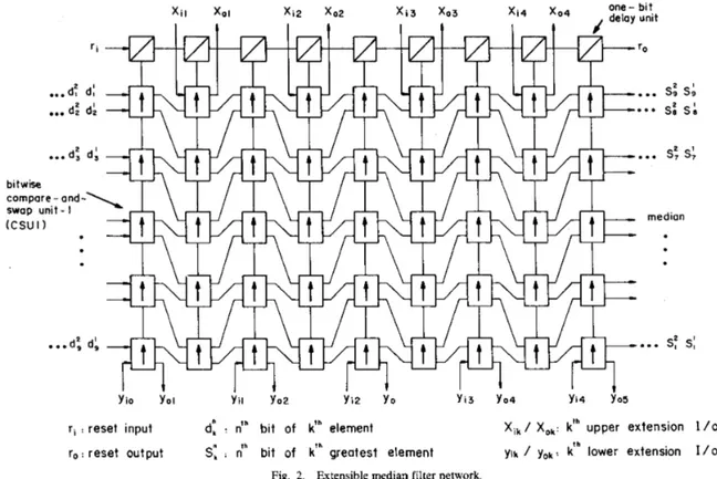
xi4 xO4 one- bit X i 3 x03
Y i o Yo1 Y i i Y o 2 Y i 2 Y o Y i 3 Y O 4 Yi4 Y o 5
ri : reset input d: :
dh
bit of k’h element Xi,/ Xok: kfh upper extension 1r o : reset output S: :
n‘“
bit of kfh greatest element Yik / Yo,: kfh lower extension IFig. 2. Extensible median filter network.
507
/ O
1 0
They satisfy the listed requirements for a general-purpose median filter. One of the networks is designed for unlim- ited word length and extensibility to larger window sizes whereas the other one is for real-time applications.
B. The Extensible Median Filter Network
The extensible median filter network consists of nine compare-and-swap stages. A compare-and-swap stage con- sists of five bitwise compare-and-swap units. Each of these units compares two 1-b numbers at its inputs and inter- changes them if necessary so that the larger one is at the “top.” At the output of the last stage, the data will be sorted such that the largest will be at the top, and the median will be in the middle. At each clock, one bit from each word (total of nine bits) enters the network and one bit of the median is obtained at the output. The flow is from the most significant bits toward the least significant bits both at the input and the output. Due to serial bitwise data flow, this structure allows arbitrary word length L
(see Fig. 2).
The bitwise compare-and-swap unit, CSU1, has two 1-b data inputs
A i
and B,, a reset input R , and two 1-b data outputs A , and Bo. It also has two internal parameters S(l/O: swap/pass) and E (l/O: equal/not equal) which are updated and stored in the CSUl (Fig. 3). Because of the
feedbacks S and E , the best structure for CSUl is a finite state machine in order to have a reliability of timing [31]. The CSUl compares
A i
andBi,
and either passes them unaltered or swaps them. Its legal operation states areequal, pass, and swap states. The present state values of S
and E show the cumulative subresult of the bit-wise
comparison of the more significant bits while the next state values indicate the new subresult.
CSUl is set to the equal state ( S = 0, E = 1) by the reset signal R at the beginning of each computation cycle. This is the instant after the least significant bit of the previous cycle leaves and before the most significant bit of the next cycle enters the CSU1. Thus, the reset signal also flows through the stages of the network. For this purpose, a chain of the bit-wise delay units is used to reset the stages at appropriate time instants (see Fig. 2). During the com- putation, the CSUl stays in the equal state ( S = 0, E = 1)
and passes the input data unaltered ( A , = A , and Bo = B , )
as long as the two input bits are equal as they flow in. However, it locks itself into the pass state when it first finds that A , > B, and passes the inputs unaltered. On the
other hand, it locks itself into the swap state when it first finds that A , < B, and swaps the inputs, A , = B, and
Bo = A,.
The extension I/O’s (x,,,’s and y,,o’s, see Fig. 2) of the extensible median filter network are used to extend the filter to window sizes larger than w = 9. If the upper and
lower extension inputs ( x , ’ s and y,’s) are connected to logic ONE and ZERO, respectively, the corresponding CSUl’s operate as delay units. If the network block diagram given in Fig. 2 is used as an array element to sort the elements of a window larger than 9, then these CSUl’s operate as usual. As a result of this, the extensibility to indefinitely larger windows is achieved: in the normal mode, it is
IEEE JOIJRNAL OF SOLID-STATE CIRCUITS, VOL. 25, NO. 2 , APRIL 1990
L s
L - E-
I compare--
and a swap-
508 A i B i-
Ai 2 Bi A0 B oAim:;:
,”:
R::
-
Ao B o Bi R : reset S : swap/pass ( l / OE : equal /not equal ( I / O )
Ai , Bi . one - bit input data B O , B. . one- bit output data
equal state /
possible to compute the exact median of a group of 9 elements using only one network. For groups of w ele- ments where w > 9, the number of networks required to find the exact medians is no more than the smallest greater integer of ( ~ / 9 ) ~ , with appropriate interconnections of the extension and data I/Os.
The extensible network described above generates its outputs with a pipeline delay of w
+
L clocks, and after the network is full, it finds one median per L clocks. The network can operate at a clock rate that is determined by the delay of one bit-wise compare-and-swap unit. Al- though the resulting speed can be sufficient for the real- time median filtering of 512x512 frames with L < 5, it is less than the real-time operation rate for 1024 X 1024 frames with L >1 .C, The Real-Time Median Filter Network
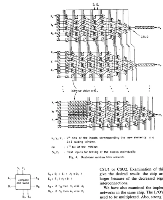
A median filter with very high throughput can be de- signed by interconnecting an L number of pipelined odd/even transposition sorter blocks in parallel [26]. In each block, the compare-and-swap units (total of six) and delay units (total of four) at the upper and lower end parts of a sorter are eliminated because they are not necessary to
for w = 9 and L = 8 is shown in Fig. 4. In this network,
the data enter in such a way that the most significant bits go to the first block, the second most significant bits to the second block, and so on. There are nine 8-b input data, and one 8-b median is obtained per clock. At every clock, three new elements enter the network, corresponding to the new elements of a sliding 3 x 3 window.
The bit-wise compare-and-swap unit, CSU2, used in this network is slightly different than CSUl in such a way that the S and E parameters of CSUl are external parameters in CSU2. These parameters are taken as inputs S, and E,
(the cumulative subresult of the bit-wise comparison of the more significant bits) from the upper block, used, updated and sent out as S, and E , (the new cumulative subresult) to the lower block. Hence, CSU2 does not have any storage or the reset input signal. The functional description of CSU2 is given in Fig. 5.
During the computation, CSU2 compares the inputs A , and B, and passes or swaps them conditionally depending on S, and E,. If E = 1 and S = 0, it passes or swaps the inputs so the larger one goes to A , and the smaller one to
Bo. On the other hand, if E = O and S = O / l , CSU2 passes/swaps the inputs, independent of the result of the comparison of the inputs. It also updates the S, and E, and sends them out as S, and E , for the comparison of the less significant bits.
The computation at each stage of a lower block starts after the corresponding stage of the upper neighborhood block completes its operation so that the S,’s and El’s are ready at the input of that stage. As a result of this, each stage of a lower block must operate one clock later com- pared to the corresponding stage of the upper block. In order to employ a proper timing, the pipeline delay units are used both at the input and output of the network (see Fig. 4).
The throughput of the network is one full-word median per clock. The clock period is determined by the delay of one CSU2. Recent VLSI technology allows the implemen- tation of CSU2 at a speed larger than the real-time rate for the 1024
x
1024 frames with L = 8.111. VLSI IMPLEMENTATION
A . VLSI Feasibility
Both the extensible and real-time median filter networks are regular arrays of bit-wise compare-and-swap and delay units. Also, their internal communication schemes are sim- ple and regular. This makes the VLSI implementations easy and straightforward. The extensible median filter chip can be packaged in a 28-pin package with 2 x 1 multi- plexed I/O’s whereas the real-time median filter chip can be packaged in a 40-pin package without multiplexed I/O’s. Furthermore, the testing of the VLSI chips may be easily accomplished by the functional test technique, since the operations of the cells can be selectively probed by find the median. The block diagram of the overall network issuing proper test vectors.
KARAMAN et al.: GENERAL-PURPOSE MEDIAN FILTER UNIT I N CMOS VLSI SI El
509
* \
1
1
bitwise delay unii.x,,y,, z , : i t h b i t s of the inputs corresponding the new elements in a
m i
S t . E l : Test inputs for testing of the blocks individually. 3 x 3 sliding window.
: i t h bit of the median
Fig. 4. Real-time median filter network.
Si E i
S o = Si + E i ( Ai < Bi 1 E, = E , ( Ai = Bi ) and swap
Bo A,= i f Sothen B, else A, B o = if Sothen A i else Bi so Eo
Fig. 5. Compare-and-swap unit-2 (CSU2). Si and E, indicate the cumu- lative subresult of the bit-wise comparison of more significant bits, while So and E, indicate the new cumulative subresult.
One may choose to implement either the extensible median filter network or the real-time network for a larger
w , but neither of the networks is preferable for a large w since the area is proportional to wz. We have chosen w = 9 because it is the minimum and the most commonly used window size in two-dimensional median filtering applica- tions. In an attempt to increase the efficiency of the silicon area use, one may consider designing a single network that can operate as either one of the median filter networks presented above, depending on the state of an external signal. This may be achieved by designing a new compare- and-swap unit which is externally selectable to operate as
CSUl or CSU2. Examination of this possibility did not
give the desired result: the chip area turned out to be larger because of the decreased regularity and increased interconnections.
We have also examined the implementation of the two networks in the same chip. The I/Os of the two networks need to be multiplexed. Also, strong buffers are needed to drive the large wiring capacitive loads due to very long wiring paths from 1/0 pads to the network I/Os. All these increase the area and decrease the throughput of the networks significantly so that the real-time operation falls into a critical state. Also, while one of the networks operates the other one cannot be used due to multiplexed
I/O’s, i.e., one of the networks will be idle at all times. The
implementation of the networks as two single chips avoids these undesired results.
B. The Chips
VLSI implementations of the algorithms consist of cir- cuit designs and generation of layouts. Our chips are
designed in 3-pm n-well double-metal CMOS, since CMOS
510 IEEE JOURNAL OF SOLID-STATE CIRCUITS, VOL. 25, NO. 2, APRIL 1990
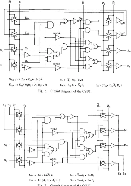
5n+1 = ( S, Enai Bi )E
En,, = En( AiBi t A, B,) + R
A,= TX A,+ S,B, Bo = S, Ai + S,B,
- - -
S, = ( Sn+ EnXi 8, )
Fig. 6. Circuit diagram of the CSU1.
Ao B O Eo S o - So = AO = SoAi SOB1 Eo = E , ( A I B l + ~ l ~ , ) Bo = S o A l + SoBI SI + El E , BI
-
Fig. 7. Circuit diagram of the CSU2.
established design procedure, and a speed comparable to NMOS. Also, the noise immunity of CMOS is better than that of NMOS [32].
Due to pipelined structure and systolic data flow, a sequential circuit design is required with two-phase nonoverlapping clocking strategy. The circuit diagrams of the CSUl and CSU2 are shown in Figs. 6 and 7. In these circuits, the inputs are latched in during
G1
= 1, and the computed outputs are sent out during +2 = l . Both of thecircuits can function correctly even if the complement of
G1
is used asG2
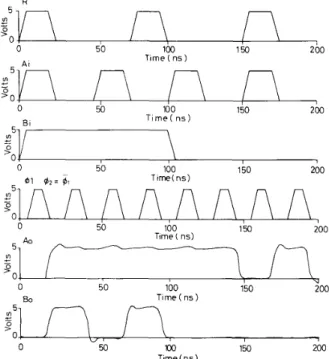
(see Fig. 8), but the operations of the circuits with two nonoverlapping clocks, and G 2 , will be more reliable. We have used standard (complementary) CMOS logic style because this logic style offers a more reliable timing, a rather easier mapping in layout, a lower power consumption, and a better noise immunity com- pared to the other styles. Furthermore, its area and speed performance is comparable with the other styles [31], [33].In the layout generation step, first the floor plans of the chips are completed. Layouts of the networks are edited hierarchically starting from the compare-and-swap units (CSU1 and CSU2), which are the basic cells. Then circuit equivalents of the layouts are extracted and simulated. For editing and simulations, we have used the Berkeley CAD tools of the University of California [34] and the VLSI tools of the University of Washmgton [35] running under the Unix operating system on a SUN160 workstation. Layouts are edited with Magic. The timing and logic simulations are performed using the SPICE, Rnl, and Esim tools. After completing the layout editing and simu- lation tasks, the chip layouts are converted to CIF and GDS2 codes to be used in fabrication. The waveforms given in Fig. 8 are the samples for the SPICE simulation results of the CSU1, which are obtained at their maximum clock rates. The complete layouts of the chips are shown in Figs. 9 and 10.
KARAMAN et ul.: GENERAL-PURPOSE MEDIAN FILTER UNIT I N CMOS VLSI R 511 I 0 50 100 150 200 T t r n e ( n s )
Fig. 10. Complete layout of the real-time median filter chip
BO Time ( n s )
0 50 xx) 150 200
Tlme ( n s )
Fig. 8. Sample of the waveforms obtained by SPICE simulation of the
csu1.
~~
~ ~~~ ~
Fig 9 Complete layout of the extensible median filter c h p
C. Testing
For the testing of the chips, the functional test method is used [36]-[38]. The testing operation is composed of the application of test vectors as inputs to the chips and the comparison of the outputs with expected results. The test vectors and the expected results are generated by the software tools written for these specific purposes.
The extensible median filter chip is tested by using a few hundred test vectors. If we apply the same element to all of the inputs, then every CSUl will act in the equal state. On the other hand, the sorted inputs (the largest one is at the “top”) will cause all of the CSUl’s to operate in the pass state. Consequently, a set of inputs sorted in reverse order (the largest one is at the “bottom”) will make the CSUl’s operate in the swap state. In this way, the CSUl’s are tested for all operation states.
The real-time median filter chip is tested using 12 288 (8 X 3 X 2’) test vectors. The Si’s and
Ei’s
at the top of the network are connected to external test control inputs S, and E,, respectively (see Fig. 4). These test control signals will be used to isolate the operation of each block from the others. The k th block can be tested individually by apply- ing logic ONE to all of the upper blocks’ inputs so that it receives the external S, and E, without any change. As aresult, each block will be tested by using 1536 (3 X
z9)
test vectors: all combinations of one-bit 9 inputs times 3, where 3 comes from the legal values of the pair SiEi(O1, 00, 10).IV. APPLICATIONS
The extensible and the real-time median filter chips can be selectively used in a general-purpose digital image or signal processor environment by means of the chip-enable signal that each chip has [39]. The exact medians of the elements, in a window size w = 9 with arbitrary word
length L , can be found by using only one extensible median filter chip. For w > 9 with arbitrary L , the number of required chips to find the exact medians is no more than the smallest greater integer of ( ~ / 9 ) ~ . In this case the chips are interconnected similarly to the configuration shown in Fig. 11. The real-time median filter chip can find the exact running medians of the elements in a window of fixed size w = 9 with fixed word length L = 8 at the real-time rate. Furthermore, the extensible and/or real- time median filter can be used for the realization of many median filtering techniques, as outlined below.
The extensible median filter is a favorable choice to realize adaptiue-length median filters [16], [40], since one can change the window size from 3 to indefinitely large ones by using the extensible median filter chp(s) by apply- ing the logic ZERO’S or ONE’S to unused inputs of the chip(s) appropriately.
For the realization of weighted median filters [13], the extensible median filter can be used with a pipelined
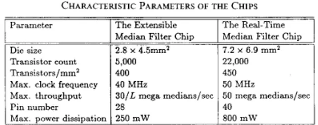
512 IEEE JOURNAL OF SOLID-STATE CIRCUITS. VOL. 25, NO. 2. APRIL 1990 U 1 1 - 4 = 1 Sorted ou1wts Inputs (1-25) Logic 0 L l l - 4 = O TABLE I
CHARACTERISTIC PARAMETERS OF THE CHIPS
I The Real-Time
I The Extensible
I Parameter I
I
Median Filter ChipI
Median Filter ChipI 2.8 x 4.5mm2 I 7.2 x 6.9 mm2
I Die size I
Transistor count Transistors/mmz Max. clock frequency Max. throughput Pin number Max. power dissipation
5,000 400
40 MHz
3O/L mega medians/sec 28
250 mW 800 mW
more, it is concluded that a general-purpose median filter unit can be formed by selectively using the chips in full- scale general-purpose digital signal or image processor environments.
Fig. 11. Interconnections of the extensible median filter chips for w = 25.
ACKNOWLEDGMENT multiplier to multiply the input data with the weight
coefficients. Since all input data of the c h p are entered to the chip directly at each move of the window, one can realize an adaptive weighted median filter by changing the weight coefficients at each position of the window on the frame.
A pair of the extensible or the real-time median filter chips can be used as a selective median filter [17] together with an external control logic consisting of two full-word subtractors and a full-word comparator.
Either the extensible or the real-time median filter chip can be used as a line-recursiue median filter [16] by loading the window elements from the frame appropri- ately.
The extensible median filter chips can be used for the realization of multilevel median filters [15] together with a reasonable external hardware.
The c h p s can be used for the realization of separable median filters [12] without any external hardware.
V. RESULTS AND CONCLUSIONS
Two single-chip median filters are designed to form a general-purpose median filter unit. One of the c h p s is designed for unlimited word length and extensibility to larger window sizes whereas the other one is for real-time video applications. The chips are implemented in 3-pm double-metal CMOS by using full-custom VLSI design techniques. The performance characteristics of the c h p s are summarized in Table I. These characteristics of the chips are comparable with those of the chips in the litera- ture, for example [41]. The extensible and real-time median
filter chips with/without a reasonable external hardware can be used for the realization of various median filtering techniques.
The main contributions of this study are the architecture of the extensible median filter and its VLSI implementa- tion. Another achievement of this study is a fast-running VLSI median filter that can meet the demands for real-time applications both today and in the near future. Further-
The authors would like to thank B. DeMey of IMEC (Belgium) for his support towards the fabrication of the chips.
REFERENCES
A. V. Oppenheim and R. W. Schafer. Digitul S i g t i d Processing. Englewood Cliffs, NJ: Prentice-Hall. 1975.
A. Kundu, S. K. Mitra, and P. P. Vaidyanathan. “Application of two-dimensional generalized mean filtering for removal of impulse noises and images,” IEEE Truns. Acoust.. Speech. Signal Process- ing, vol. ASSP-32, no. 3, pp. 600-609, June 1984.
J. W. Tukey, “Nonlinear (nonsuperposable) methods for smoothing data,” in Conf. Rec. E A S C O N , 1974, p. 613.
N. C. Gallagher, Jr. and G. L. Wise, “A theoretical analysis of the properties of median filters,” IEEE Truns. Acoust., Speech, Sigrid Processing, vol. ASSP-29, pp. 1136-1141, Dec. 1981.
T. A. Nodes and N. C. Gallagher, Jr.. “Median filters: Some modifications and their properties,” IEEE Truris. Acoust., Speech,
Signal Processing. vol. ASSP-30, no. 5 , pp. 739-7:>, Oct. 1982. E. Ataman, V. K. Aatre. and K. M. Wrong, Some statistical properties of median filters,” I E E E Truns. Acoust., Speech S i g d Processing. vol. ASSP-29, pp. 1073-1075, Oct. 1981.
J. Neejarvi, P. Heinonen, and Y. Neuvo, “Sine wave responses of median filters,” in Proc. IEEE S.vmp. Circuirs Svst. (Espoo. Fin-
land), 1988, pp. 1503-1506.
L. R. Rabiner. M. R. Sambur. and C. E. Schmidt. “ADDlications of II
a nonlinear smoothing algorithm to speech processing,” I E E E Truns. Acousr., Speech, Signul Processing. vol. ASSP-23, pp. 552-557, Dec. 1975.
E. Ataman and E. Alparslan, “Application of median filtering algorithm to images,” Electron. Div., Marmara Research Inst.. Gebze. Turkev. Tech. ReD. U1 78/10. SeDt. 1978.
A. C. Bovik, “Streaking &in median filteied images,” I E E E Truns. Acousr., Speech. Signal Processing, vol. ASSP-35, pp. 493-503, Apr. 1987.
Y. H. Lee and S . A. Kassam, “ G e n e r a p d median filtering and related nonlinear filtering techniques, IEEE Truns. Acousr., Speech, Signul Processing, vol. ASSP-33, pp. 672-683, June 1985. M. P. McLoughlin and G. R. Arce, “Deterministic properties of the recursive separable median filter,” IEEE Truns. Acoust., Speech,
S i g w l Processing. vol. ASP-35, pp. 98-106, Jan. 1987.
T. Loupas, W. N. McDicken. and P. L. Allan, “Noise reduction in ultrasonic images by digital filtering,” Brit. J . Radio/., vol. 60, pp. 389-392, Apr. 1987.
C. G. Boncelet, Jr.. “Recursive algorithms and VLSI implementa- tions for median filtering,” in Proc. I E E E Synip. Circuits Syst. (Espoo, Finland), 1988. pp. 1745-1747.
G. R. Arce. P. J. Warter, and R. E. Foster, “Theory and VLSI implementation of multilevel median filters,” in Proc. IEEE S.vmp. Circuits S.v.sr. (Espoo, Finland), 1988, pp. 2795-2798.
H. M. Lin and N. Willson, Jr., “Median filters with adaptive length.” I E E E T r a m . Circuirs S-vst. vol. 35, pp. 675-690, June 1988. S. J. KO. Y . H. Lee, and A. T. Fam, “Selective median filters,’’ in Proc. I E E E Svmp. Circuirs Svsr. (ESDOO. Finland). 1988. DD.
KARAMAN et al. : GENERAL-PURPOSE MEDIAN FILTER UNIT I N CMOS VLSI 513 T. S. Huang, G. J. Yang, and G. Y. Tang, “ A fast two-dimensional
median filtering algorithm,” IEEE Trans. A c o w t . . Speech. Signul Processing, vol. ASSP-27. pp. 13-18, Feb. 1979.
E. Atarnan, V. K. Aatre, and K. M. Wong, “ A fast method for real-time median filtering,” I E E E Truns. Acoust., Speech, Signal Processing, vol. ASSP-28, pp. 415-421, Aug. 1980.
V. V. B. Rao and K. S. Rao, “A new algorithm for real-time median filtering,” IEEE Trans. Acoust., Speech, Signal Processing, vol. ASSP-34, pp. 1674-1675, Dec. 1986.
M. 0. Ahmad and D. Sundararajan, “A fast algorithm for two- dimensional median filtering,” IEEE Trans. Circuits Svst., vol. J. T. As!da and T. G. Campbell, On computation of the running median, I E E E Truns. Acoust., Speech, Signal Processing. vol. 31, pp. 572-574, Apr. 1989.
M. Karaman and L. Onural, “New radix-2-based algorithm for fast median filtering,” Electron. Lett., vol. 25, pp. 723-124, May 1989. D. L. Knuth, The Art of Coniputer Programming-Searching und Sorting, vol. 3.
C. D. Thompson, “The VLSI complexity of sorting,” IEEE Trans. Computers, vol. C-32, pp. 1171-1184, Dec. 1983.
K. Oflazer, “Design and implementation of a single-chip 1 - D median filter,” IEEE Truns. Acoust., Speech, Signul Processing. M. J. Foster and H. T. Kung, “The design of special purpose VLSI chps,” I E E E Computer, pp. 26-40, Jan. 1980.
H. T. Kung, “Why systolic architectures?,” I E E E Computer, pp. 37-46, Jan. 1982.
S. Y. Kung, H. J. Whitehouse, and T. Kailath, Eds., V L S I und Modern Signul Processing. Englewood Cliffs, NJ: Prentice-Hall, 1985.
C. Mead and L. Conway, Introduction to V L S I S-vstems. Reading. MA: Addison-Wesley, 1980.
N. Weste and K. Eshraghan, Principles of C M O S V L S I Design. Reading MA: ‘Addison-Wesley, 1985.
R. D. Davis, The case for CMOS.” IEEE Spectrum, pp. 26-32, Oct. 1983.
L. A. Glasser and D. W. Dobberpuhl, The Design and Analvsis of V L S I Circuits.
Berkelev C A D Tools User’s Manual, EECS Dep.. Univ. of Calif., Berkeley, 1986.
V L S I Tools Reference Manual, NW Lab. Int. Sys., Dep. Computer Sci., Univ. of Washington, Seattle, TR#87-02-01, Release 3.1, Feb. 1987.
J. A. Abraham and W. K. Fuchs, “Fault and error models for VLSI,” Proc. I E E E , vol. 74. pp. 639-654, May 1986.
F. F. Tsui, L S I / V L S I Testability Design. New York: McGraw- Hill, 1986.
R. J. Feugate, Jr. and S. M. McIntyre, Introduction to V L S I Testing.
P. A. Ruetz and R. W. Brodersen, Architectures and design techniques for real-time image-processing IC’s,” I E E E J . Solid-State Circuits, vol. SC-22, pp. 233-250, Apr. 1987.
W. J. Song and W. A. Pearlman, “Edge-preserving noise filtering based o n adaptive windowing,” IEEE Trans. Circuits Svst., vol. 35, T. Denayer, E. Vanzieleghem, and P. G. A. Jespers, “A class of multiprocessors for real-time image and multidimensional signal processing,” I E E E J . Solid-State Circuits, vol. 23, pp. 630-638, June 1988.
CAS-34, pp. 1364-1374, NOV. 198:.
Reading MA: Addison-Wesley, 1973.
vol. ASSP-31, pp. 1164-1168, Oct. 1983.
Reading, MA: Addison-Wesley, 1985.
Englewood Cliffs, NJ: Prentity-Hall, 1988.
pp. 1048-1054, Aug. 1988.
cessing, computer-aide :d
Mustafa Karaman was born in Balikesir, Turkey, in 1964. He received the B.S. degree from the Middle East Technical University, Ankara, Turkey, and the M.S. degree from Bilkent Uni- versity, Ankara, Turkey, in 1986 and 1988, re- spectively, both in electrical and electronics engi- neering. He is studying for hs Ph.D. degree in the Department of Electrical and Electronics En- gineering at Bilkent University, where he has been a Research Assistant since 1986. His pre- sent research interests include VLSI signal pro- design tools for VLSI, and circuit simulation.
Levent Onural (S’82-M85) was born in Izmir, Turkey, in 1957. He received the B.S. (high hon- ors) and M.S. degrees in electrical engineering from the Middle East Technical University, Ankara, Turkey, in 1979 and 1981, respectively, and the Ph.D. degree in electrical and computer engineering from the State University of New York at Buffalo in 1985. He was a Fulbright Scholar between 1981 and 1985.
After a Research Assistant Professor position at the Electrical and Computer Engineering De- partment of the State University of New York at Buffalo, he joined the Electrical and Electronics Engineering Department of Bilkent University, Ankara, Turkey, where he is an Associate Professor at present. His present research interests are in signal processing, image processing, holography, fractal models, and signal processing hardware.
Dr. Onural is a member of SPIE.
Abdullah Atalar (M88) was born in Gaziantep, Turkey, in 1954. He received the B.S. degree from the Middle East Technical University, Ankara, Turkey, in 1974, and the M.S. and Ph.D. degrees from Stanford University, Stanford, CA, in 1976 and 1978. respectively, all in electrical engineering. His thesis work was on reflection acoustic microscopy.
From 1978 to 1980 he was a first Post-Doc- toral Fellow and later an Engineering Research Associate at Stanford University, where he con- tinued h s work on acoustic microscopy. For eight months he was with Hewlett Packard Laboratories. Palo Alto, CA, engaged in photoacoustics research. In 1980 he joined the Middle East Technical University as an Assistant Professor. From 1982 to 1983 he was on leave from the University with Ernst Leitz Wetzlar, Wetzlar, West Germany, where he was involved in the development of the commercial acoustic microscope. He is presently an Associate Professor and Chairman of the Electrical and Electronics Engineering Department at Bilkent University, Ankara, Turkey. His current research interests include computer-aided design in electrical engineering, acoustic imaging, and linear acoustics.